ISOMAG ML 110 Specification sheet

OPERATING AND INSTALLATION MANUAL
CONVERTER
ML 110
Release number: 110_EN_IS_R8_3_9X – The last three digits of file name identify the software version which the manual
refers to; it is visualized at the instrument start up, or by specific function on DIAGNOSTIC menu.
Official Isoil dealer for The Netherlands:

2
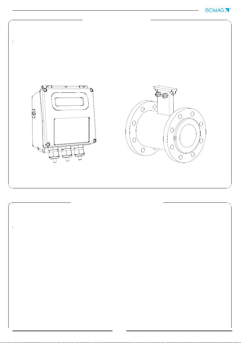
INTRODUCTION ..................................................................................... 3
SAFETY INFORMATIONS........................................................................ 3
SAFETY CONVENTIONS .............................................................................. 4
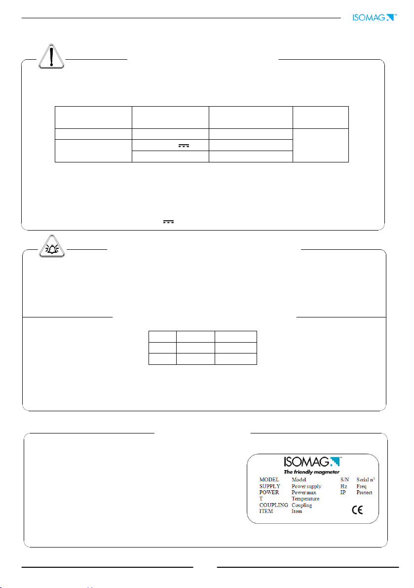
TECHNICAL CHARACTERISTICS ............................................................ 5
ENVIRONMENTAL USE CONDITIONS........................................................... 5
AMBIENT TEMPERATURE............................................................................ 5
Data plate.................................................................................................. 5
ELECTRIC CHARACTERISTICS..................................................................... 5
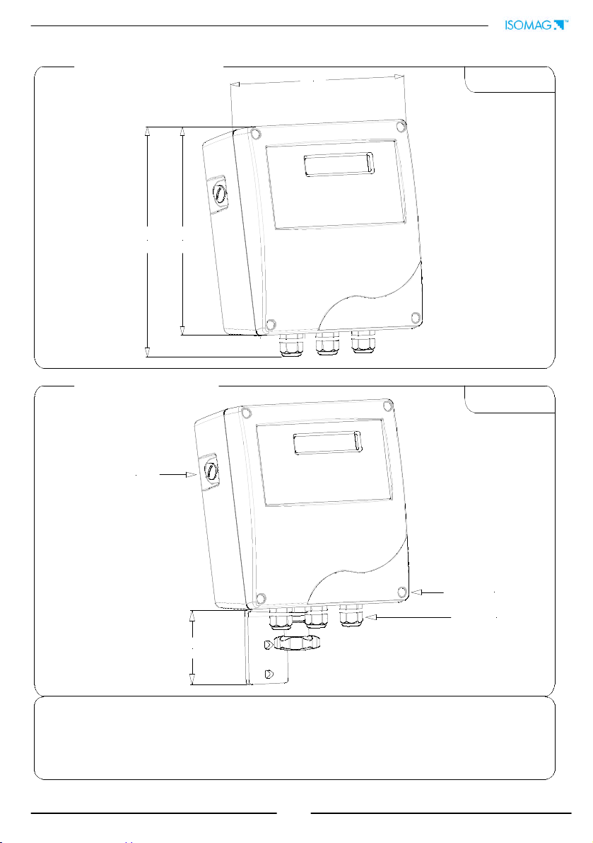
DIMENSIONS (PA6 HOUSING) .................................................................... 6
DIMENSIONS (ALUMINUM HOUSING) ......................................................... 7
ELECTRICAL CONNECTIONS.................................................................. 8
GROUNDING INSTRUCTIONS ..................................................................... 8
CONVERTER POWER SUPPLY...................................................................... 8
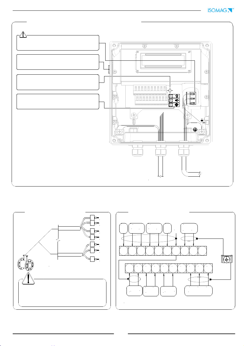
PA6 CONVERTER INTERNAL VIEW .............................................................. 9
PA6 CONVERTER TO SENSOR ELECTRICAL CONNECTIONS .......................... 9
ALUMINUM CONVERTER INTERNAL VIEW ................................................. 10
ALUMINUM CONVERTER TO SENSOR, ELECTRICAL CONNECTIONS ............ 10
DIGITAL INPUT .................................................................................... 11
INPUT ON/OFF OPERATION...................................................................... 11
OUTPUT WIRINGS................................................................................ 12
DISPLAY FLAGS AND LED WARNING INTERPRETATION................... 13
CONVERTER ACCESS ............................................................................ 14
KEYPAD................................................................................................... 14
BLIND CONFIGURATION .......................................................................... 14
ACCESSING THE TRANSMITTER FUNCTIONS AT START-UP (Power On)...... 15
FLOW RATE VISUALIZATION............................................................... 16
ACCESS CODES ..................................................................................... 17
QUICK START MENU............................................................................. 18
ACCESS TO THE CONFIGURATION MENU ........................................... 19
EXAMPLE ................................................................................................. 20
FUNCTIONS MENU................................................................................ 22
FUNCTIONS DESCRIPTION ....................................................................... 25
ALARMS................................................................................................. 32
ISOMAG RETURN MATERIAL ............................................................... 33
CONFORMITY DECLARATION .............................................................. 35
ADDRESSES .......................................................................................... 36
INDEX

3
INTRODUCTION
These operating instructions and description of device functions are provided as part of the
scope of supply. They could be modified without prior notice. The improper use, possible
tampering of the instrument or parts of it and substitutions of any components not original,
renders the warranty automatically void.
The converter is to be used only to be coupled with a sensor to realize a measuring device,
flow meter, that is to be used for measuring the flow of conductive liquids in closed pipes
with conductivity greater than 5µS/cm.
The converter could be coupled directly on the sensor (compact version) or coupled to the
sensor by cable supplied with it (remote version).
The reproduction of this manual and any supplied software is strictly forbidden.
SAFETY INFORMATIONS
Any use other than described in this manual affects the protection provided by the
manufacturer and compromises the safety of people and the entire measuring system and
is, therefore, not permitted.
The manufacturer is not liable for damaged caused by improper or non-designated use.
1) Transport the measuring device to the measuring point in the original packaging. Do
not remove covers or caps until immediately before installation. In case of cartons
packaging it is possible to place one above the other but no more than three cartons.
In case of wooden packaging do not place one above the other.
2) Disposal of this product or parts of it must be carried out according to the local
public or private waste collection service regulations.
3) The converter must only be installed, connected and maintained by qualified and
authorized specialists (e.g. electrical technicians) in full compliance with the
instructions in these Operating Instructions, the applicable norms, legal regulations
and certificates (depending on the application).
4) The specialists must have read and understood these Operating Instructions and
must follow the instructions it contains. The Operating Instructions provide detailed
information about the converter. If you are unclear on anything in these Operating
Instructions, you must call the ISOIL service department.
CONVERTER SENSOR

4
5) The converter should only be installed after have verified technical data provided in
these operating instructions and on the data plate.
6) Specialists must take care during installation and use personal protective equipment
as provided by any related security plan or risk assessment.
7) Never mount or wire the converter while it is connected to the power supply and
avoid any liquid contact with the instrument’s internal components. To connect
remove the terminals from the terminal block.
8) Before connecting the power supply check the functionality of the safety equipment.
9) Repairs may only be performed if a genuine spare parts kit is available and this
repair work is expressly permitted.
10) For the cleaning of the device use only a damp cloth, and for the
maintenance/repairs contact the service center (for details see the last page).
11) To return the product back for service complete and return the meter with form
found in the last pages of these operating instructions.
Before starting up the equipment please verify the following:
Power supply voltage must correspond to that specified on the data plate
Electric connections must be completed as described
Ground (earth) connections must be completed as specified
Verify periodically (every 3-4 months):
The power supply cables integrity, wiring and other connected electrical parts
The converter housing integrity
The suitable tightness of the sealing elements
The front panel integrity (display and keyboard)
The mechanical fixing of the converter to the pipe or wall stand.
SAFETY CONVENTIONS
DANGER
Warning indicates an action or procedure which, if not performed correctly,
can result in injury or a safety hazard. Comply strictly with the instructions
and proceed with care.
WARNING
Caution indicates an action or procedure which, if not performed correctly, can
result in incorrect operation or destruction of the device. Comply strictly with
the instructions.
NOTES
Note indicates an action or procedure which, if not performed correctly, can
have an indirect effect on operation or trigger an unexpected response on the
part of the device.

5
TECHNICAL CHARACTERISTICS
ENVIRONMENTAL USE CONDITIONS
The converter can be installed internally or externally
Altitude: from –200m to 2000m (from -656 to 6560 feet)
Humidity range: 0-98%, 0-85% without condensation for PA6 housing
AMBIENT TEMPERATURE
If the converter is supplied in compact version to the sensor, consider the ambient
temperatures more restrictive, otherwise refer to the respective manuals.
*For discontinuous use, a thermostat heat source installation may be necessary.
Data plate
On the data plate there is some technical information:
MODEL: Converter Model
S/N: Serial Number of the converter
SUPPLY: Main power supply
Hz: Supply frequency (AC)
POWER: Maximum power consumption
IP: Protection grade
T: Operating temperature
COUPLING: Serial number of sensor coupled
ITEM: free for user
Min. * Max
°C -10 50
°F 14 122
ELECTRIC CHARACTERISTICS
Converter classification: class I, IP65 for PA6 housing, IP67 for aluminum housing,
installation category (overvoltage) II, rated pollution degree 2.
Power supply
versions
Power supply
voltage
Power supply
frequency
Max
power
HV 100-240V~ 44-66Hz
6W
LV 18-45V //
18-45V~ 44-66Hz
Voltage variations must not exceed ±10% of the nominal one.
All instrument versions can be equipped with all power supply versions.
Input/output insulated up to 500V.
The output 4-20mA (optional) is electrically connected to the ON/OFF outputs and
the output power supply (24V ).

6
DIMENSIONS (PA6 HOUSING)
COMPACT VERSION
SEPARATE VERSION
127
129
168
124
78
CABLE GLAND
COVER SCREW
IF2 CAP
TORQUES
To guarantee the housing’s IP degree the following torques are required:
cover screws: 0.5Nm
cable glands: 4Nm (in reference conditions)
IF2 cap: 4Nm
Weight: 0.5kg
Weight: 1kg

7
DIMENSIONS (ALUMINUM HOUSING)
COMPACT VERSION
SEPARATE VERSION
193
169
160
78
CABLE GLAND
COVER SCREW
IF2 CAP
TORQUES
To guarantee the housing’s IP degree the following torques are required:
cover screws: 0.8Nm
cable glands: 1.8Nm (in reference conditions)
IF2 cap: 2Nm
Weight: 1.5kg
Weight: 2kg

8
L(-)
N(+) M3
M3
ELECTRICAL CONNECTIONS
ALWAYS ensure that the converter and the sensor are grounded (earthed) correctly. The
grounding of the sensor and converter ensures that the equipment and liquid are
equipotential.
Before connecting the power supply, verify that the mains voltage is within the limits
indicated on data plate.
For the connections use only approved conductors, with fire-proof properties, whose
section varies from 0.25mm2to 2.50mm2, based on distance/power; additionally fix
the power supply wires with a additional fastening system located close to the
terminal.
The power supply line must be equipped with an external protection for overload
current (fuse or automatic line breaker).
Provide in close proximity the converter a circuit breaker easily accessible for the
operator and clearly identified; whose symbols must conform to the electrical safety
and local electrical requirements.
Ensure that the component complies with the requirements of the standard for
electrical safety distance.
Check chemical compatibility of materials used in the connection security systems in
order to minimize electrochemical corrosion. In the aluminum housing it should
avoid direct contact between the ground connection cable and the aluminum
housing. It is therefore recommended to connect the safety ground cable, by placing
it between the washer and the metal bracket on the related terminal or use an
eyelet terminal crimped on the ground protection cable.
The sensor, hardwired inputs and outputs are connected to the converter through
terminal blocks located inside the converter.
To locate the terminal block loosen the 4 screws on the front cover. When the front
cover is lifted, the terminal block is visible. The terminal block is the hardwire
connection of the converter to external equipment, including the sensor.
The following pages give informations on the terminal block numbering, and the
respective connecting of the sensor cables, and inputs/outputs.
GROUNDING INSTRUCTIONS
CONVERTER POWER SUPPLY
PA6 HOUSING ALUMINUM HOUSING

9
PA6 CONVERTER INTERNAL VIEW
PA6 CONVERTER TO SENSOR ELECTRICAL CONNECTIONS
Power supply
12345678910
11 12 13 14 15 16 17 18 19 20
IF2 socket
Power supply
Keyboard
RS 485* : OPTIONAL, PROVIDED EXLUSIVELY BY THE MANUFACTURER
1
2
3
4
11
12
13
E1
E2
C
SH
SH
B1
B2
ALL SENSORS
123456789
10
11121314151617181920
-
EC
+
SH
OUT2 OUT1 24V
24V
E1
E2
C
4-20mA
ELECTRODES
EC
+-
B
A
RS 485* INPUT
-
+
SH
B2 B1 SH
COILS
SEPARATE VERSION
TERMINAL BLOCK
Electrodes cable sudden
movements can cause noise
during measurement
Max cable length: 20m
Signalling LED: see display flags and led warning
interpretation section

10
Power supply
SENSOR cable
Shield
ALUMINUM CONVERTER INTERNAL VIEW
Signalling LED: see display flags and led warning
interpretation section
IF2 socket
Keyboard
123456789
10
11121314151617181920
-
E
C
+
SH B2 B1
OUT2 OUT1 24V
24V
COILS
E1
E2
C
4-20mA
ELECTRODES
E
C
+
-
B
A
RS 485* INPUT
-
+
RS 485* : OPTIONAL, PROVIDED EXLUSIVELY BY THE MANUFACTURER
1
2
3
4
11
12
13
E1
E2
C
SH
SH
B1
B2
ALL SENSORS
SEPARATE VERSION
TERMINAL BLOCK M1
Electrodes cable sudden
movements can cause noise during
measurement
Max cable length: 20m
ALUMINUM CONVERTER TO SENSOR, ELECTRICAL CONNECTIONS
Power supply

11
0-1,5 V
3-40 V
AUTOCALIB. OFF
T
RESET
0-1,5 V
3-40 V
Tmin = 100ms
BLOCK
0-1,5 V
3-40 V
T
0-1,5 V
3-40 V
DIGITAL INPUT
INPUT ON/OFF OPERATION
3/40 Vdc (ON)
0/1.5 Vdc (OFF)
5 (+)
6 (-)
10 K
5
6
20
0
15
+24
10 K
Auto-calibration
Reset totalizers
Block totalizers
Block totalizers
Totalizers active
Necessary conditions for enabling the function
Tmin<T<1sec. = autocalibration
T > 1sec. = Auto zero
POS. 5.6 ENABLED (Autozero calibration external
command)
POS. 5.1 to 5.4 ENABLED (partial positive or reverse flow
totalizers reset enable).
POS. 5.5 ENABLED (totalizers counting lock command)
POS. 5.7 ENABLED (range change)
Necessary conditions for enabling the function
Range change
Scale 2
Scale 1
10Hz
20Hz
50Hz
80Hz
150Hz
220ms
110ms
45ms
30ms
15ms T must be > Tmin
SAMPLE RATE Tmin SAMPLE RATE Tmin
External power supply
Internal power supply

12
24V COMMON
+24V INTERNAL
mA
9 (+)
10 (-)
I4-20mA OUT
Output 4-20mA
Opto-insulated output
Maximum load: 1000Ω
Maximum voltage without load: 27V
Refresh frequency is the same of the sample
frequency of the connected sensor
Protected against persistent over voltages to
maximum 30V
There is a converter load CHECK on the 4–20mA output; to disable this
function set the value "mA v.fault" to 0 (Pos. 4.4)
OUTPUT WIRINGS
NOTE: shielded cables are recommended for inputs and outputs wiring.
Output on/off 1250Hz
Opto-insulated output with floating collector and
emitter terminals freely connectable
Maximum switching voltage: 40V
Maximum switching current: 100mA
Maximum saturation voltage between collector
and emitter @100mA: 1.2V
Maximum switching frequency (load on the
collector or emitter, RL=470, VOUT=24V ):
1250Hz
Maximum reverse current bearable on the input
during and accidental polarity reversion (VEC):
100mA
Insulation from other secondary circuits: 500V
16 (out1)
18 (out2)
17 (out1)
19 (out2)
43V

13
1 2 3 4 5 6 7 8 9 10
11 12 13 14 15 16 17 18 19 20
LED INTERPRETATION
PERMANENT LIGHT: initialization
FLASHING LIGHT (1 sec.): normal function
FLASHING LIGHT (<1 sec.): alarm on
The LED signals the alarm status only if the display shows one of
the suitable visualization screens
FLAGS INTERPRETATION
FLAG DESCRIPTION
MAlarm max activated
mAlarm min activated
!
- Interruption coils circuit
- Signal error
- Empty pipe
CCalibration running
SSimulation
Pulse output saturation (reduce
TIME PULSE )
At ‘Power on’ of the converter, the user will see the following display screen. In the
top right hand corner there may be a range of symbols. The symbols can be
interpreted from the table below. Interpretation of the flashing LED can be made
from the LED interpretation table at the bottom of this page.
DISPLAY FLAGS AND LED WARNING INTERPRETATION
LED
FLAGS

14
BLIND CON
FIGURATION
For the converters without keyboard (blind
configuration), the programming is made
through ISOCON (cable and software needed).
Being the housing closure dependent by the
installer, the IP degree may be compromised, so
follow the torques mentioned.
SHORT PRESSING (< 1 SECOND):
Enters/leaves the selected function
Enables the main menu for the converter configuration
Cancels the selected function under progress
LONG PRESSING (> 1 SECOND):
Leaves the current function, in the Quick start or Main menus.
Enables the ‘EXECUTE?’ prompt in the Main menu functions, and total reset
request (when enabled) from the required function
Confirms the selected function
SHORT PRESSING (< 1 SECOND):
Moves the cursor rightwards on the input field
Accesses to the following subject in the Quick start or Main menus
Changes the display of the process data
LONG PRESSING (> 1 SECOND):
Moves the cursor leftwards on the input field
Accesses to the previous subject in the Quick start or Main menus
SHORT PRESSING (< 1 SECOND):
Increases the numeric figure or the parameter selected by the cursor
Accesses to the previous subject in the Quick start or Main menus
Batch start/stop (when enabled)
LONG PRESSING (> 1 SECOND):
Decreases the numeric figure or the parameter selected by the cursor
Accesses to the next subject in the Quick start or Main menus
KEYPAD
CONVERTER ACCESS
KEYPAD M3
The keypad is accessible by loosening the 4 cover screws and
opening the front cover of the converter. Three KEYS are set
aside of the M3 power supply terminal block, allowing the user
to change display visualizations and select functions. Ensure
that the power supply cover is closed.

15
Active scale
Flow rate visualization
* Direct/Reverse totalizer
visualization
Alternate visualization
* Direct totalizer
Reverse totalizer
Currency value
Alarm description
Sampling frequency
* Direct Reverse totalizer
Flow speed
Flow rate visualization Flow rate visualization
Push keypad button
indicated to move
between pages
Push keypad button
indicated to move
between pages
Push keypad button
indicated to move
between pages
ACCESSING THE TRANSMITTER FUNCTIONS AT START-UP (Power On)
Example of visualized display pages at start-up
The direct exposure of the
transmitter
to the solar rays, could damage the
liquid crystal display.
CURRENCY FUNCTION ENABLE
* The maximum digits shown by the totalizer is 999.999.999 regardless of the number of user selected
decimals (see Pos 2.3). Beyond this value the totalizers are set to zero.
Note: The user will see the
screen displayed (left) at
power on of the transmitter.
Use the keys on the keypad as
indicated centrally on this
page to move between the
screens shown (not all
shown).

16
The ML 110 can show a 5 digit character display for flow rate units; this mean the
maximum flow rate value that can be represented on the display is 99999 (no matter the
positioning of the decimal point). The minimum is 0.0025.
The representable measure unit depends from sensor flow rate and diameter; the
permitted units are those, set the instrument full scale value, allow to be represented with
a numerical field which the maximum value do not exceed 99999.
Example for DN 300:
- Full scale value: 3m/s
-PERMITTED measure unit (example): l/s (216.00); m3/h (777.60); m3/s (0.2160)
-NOT PERMITTED measure unit (example): l/h (777600)..
FLOW RATE VISUALIZATION

17
Functions in the converter main menu are enabled by the access codes. The information of
this manual is related to all the functions available with the L2 level. All the functions
available through higher level are protected and reserved to the service.
Description of the L2 access code
(menu “11 Internal data” pos. 11.1)
with code L2 = 000000 (only with this code) you can disable the L2 code request
*with L2 customized (freely chosen by the user) you can program all the functions
up to L2 security level, entering this code whenever you enter the Main menu.
* ATTENTION: take careful note of the customized code, since there is no way for the
user to retrieve or reset it if lost.
Factory preset access codes
The converter is delivered with the default L2 (level 2) access code:
111111
ACCESS CODES

18
The set up functions (batching, regulation,
flow and SMART measure)
automatically the instrument (filters)
for the operation set modifying optimally the
parameters related to the function chosen.
To enable one of four types operation press the key
while the function is highlighted,
to confirm the changes press the key.
Filters
settings for different S.rate (sensor menu, not user modifiable):
Batching Regulation Flow measure
MFSLN MFFLN MFSLN MFFLN MFSLN MFFLN
10Hz 0 0 10 0 20 0
20Hz 0 0 5 0 10 0
50Hz 0 0 2 0 4 0
80Hz 0 0 1.3 0 2.5 0
150Hz 0 0 0.7 0 1.3 0
See the functions description section for more details regarding
filters
QUICK START MENU
The user has immediate access to the Quick Start menu when the converter is powered up
by pressing the
key. If access to the quick start menu does not occur, then it has been
disabled through the function 8.4
See function menu section
Automatic parameters optimization (see below)
Access to all functions
flow and SMART measure)
configure
for the operation set modifying optimally the
while the function is highlighted,
settings for different S.rate (sensor menu, not user modifiable):
SMART measure
MFSLN MFFLN
100 10
50 5
20 2
12.5 1.25
6.7 0.67
filters
.
The user has immediate access to the Quick Start menu when the converter is powered up
key. If access to the quick start menu does not occur, then it has been
Automatic parameters optimization (see below)

19
Functions can be accessed by the keyboard in two different ways:
The Quick start menu makes direct access possible to a range of principal
functions for setting the scale reading and display characteristics of the sensor.
Quick start menu can be enabled by function 8.4 (menu display)
Through the Main menu it is possible to access functions with the access code
level 2. These control the sensor’s monitoring, data processing, input/output as
well further display options.
The following example shows how to change the Full scale by Quick Start menu; the
second illustrates how to change the function by the Main menu.
The converter configuration menu can be accessed in two different ways:
1) by ISOCON interface
2) by keyboard of converter
Isocon is a Windows
®
software
that allows to set all the converter
functions and personalize the
menu (IF2 is required), see
suitable manual for details.
ACCESS TO THE CONFIGURATION MENU
BY THE KEYBOARD
Factory pre-setting:
QUICK START MENU=ON
ACCESS TO THE CONFIGURATION MENU
A
CCESS TO THE CONFIGURATION MENU BY ISOCON INTERFACE

20
EXAMPLE: “Quick start menu” function modification. Full scale value 1
(Fs1) from 4dm³/s to 5dm³/s.
Access the function “Fs1” by
pressing the button indicated for less
than 1 second
Push the key repeatedly and rapidly
to move the cursor to the value to
modify
Confirm the new value with a
short press of the key (less
than 1 second)
Long push to leave the quick
start menu and return to the
initial visualization page
Initial
visualization
page
To increase the value press
the upper key for short
periods of less than 1 second,
to reduce the value press the
upper key for more than 1
second repeatedly
Enter in the “Quick start menu”
The keypad button to be pressed at
each step is indicated by the icon
symbol place on one of the three
keys of the keypad (here lower key)
Other manuals for ML 110
1
Table of contents
Other ISOMAG Media Converter manuals