LM2XX/DC2XX User Manual
4
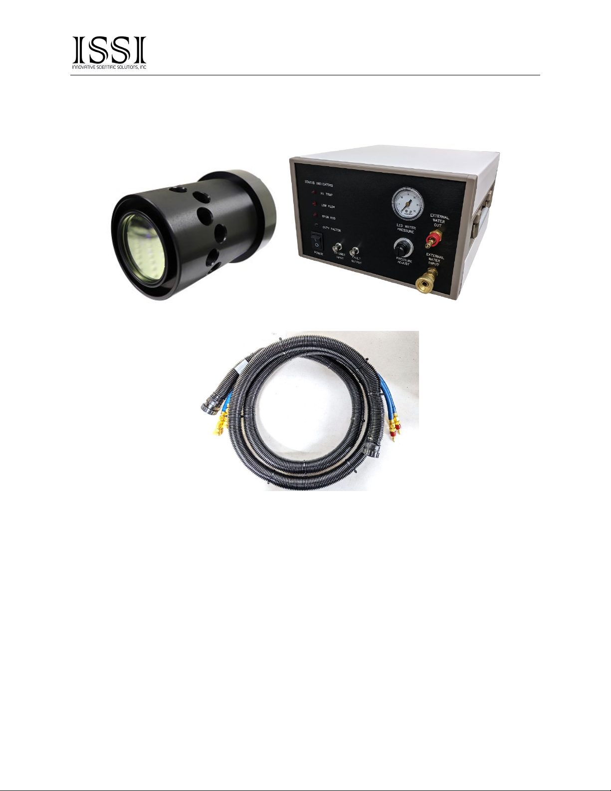
LED Illumination Lamps
Light emitting diode (LED) arrays are the most convenient and cost-effective means to excite fluorescent
dyes in experimental measurement studies including pressure and temperature sensitive paints to and
particle shadow velocimetry. Using the correct light source is critical to the accuracy of the measurement.
Optical measurement techniques require a sufficiently energetic, low noise, stable illumination source if
quality data is to be acquired. Any variation in output illumination from the excitation source will cause
measurement errors. ISSI LED arrays contain proprietary optical and electrical filtering to achieve very
stable, narrow-band illumination.
All models of LEDs are available in 400- and 460-nm wavelengths standard. Other wavelengths are available
upon request.
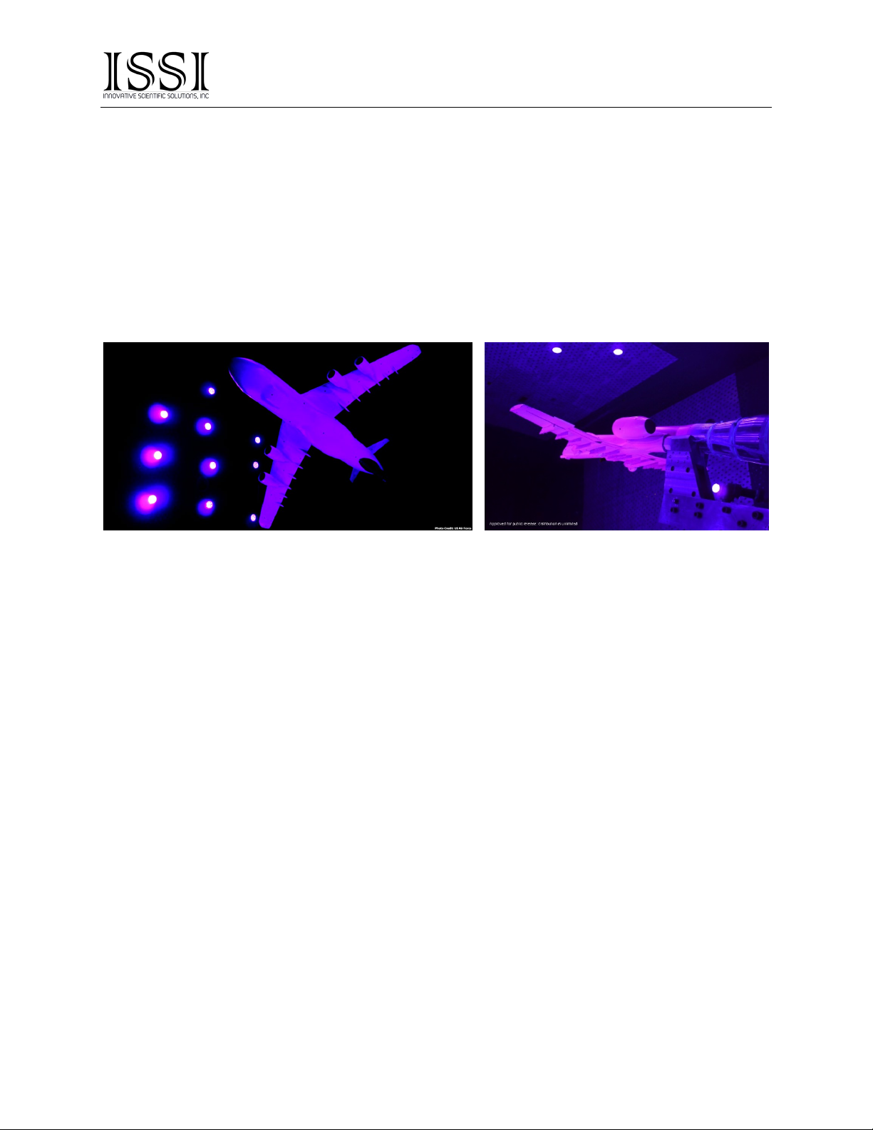
ISSI LEDs Mounted in AEDC 16T Wind Tunnel During Pressure Sensitive Paint Tests,
Photo Credit US Air Force
Uses
Molecules within pressure sensitive paint are excited by a narrow band LED light source of a specific peak
wavelength. Once excited, these molecules will either fluoresce, emitting a photon of a longer wavelength,
are quenched by local oxygen molecules (pressure sensitive paint) or are thermally quenched (temperature
sensitive paint). This quenching rate determines the fluorescent intensity of the paint layer. The fluorescent
levels can be used to estimate pressure or temperature using a previously determined calibration of the paint.
Particle Shadow Velocimetry uses a pulsed LED light source to characterize seeded flow fields near
surfaces in small regions of interest in water and air. The technique is a cost-effective alternative to some
Particle Image Velocimetry (PIV) applications that uses shadows cast by particles to track movement rather
than the traditional light scattering PIV technique using expensive lasers.
Schlieren photography is a technique utilized to image fluid density gradients. The density gradient of the
fluid gives rise to refractive index changes which distort the collimated beam of light between two mirrors and
thus the point of focus. Using a knife edge, variable density slide or color slides at the focus to exploit this
effect allows high-contrast imaging of otherwise nearly invisible density gradients.