Itm HOLEMAKER PRO 55 User manual

HOLEMAKER PRO 55
Holemaker Portable Magnetic Drilling Machine
OPERATOR’S MANUAL
Holemaker Portable Magnetic Drilling Machine
OPERATOR’S MANUAL
WARNING!
BEFORE USE,ENSURE EVERYONE USING THIS MACHINE READS AND UNDERSTANDS
ALL SAFETY AND OPERATING INSTRUCTIONS IN THIS MANUAL .
esahcruPfoetaD#laireS
HOLEMAKER PRO 50
BEWARE OF
ROTATING
MACHINE PARTS
LINE VOLTAGE
PRESENT
NEVER PLACE
FINGERS NEAR
CUTTING AREA OR
MACHINE ARBOR
HEARING PROTECTION
REQUIRED
EYE PROTECTION
REQUIRED
Ver: 1.20 07/10/2015
Ver: 1.05 10/07/2023

HMPRO55 OPERATOR’S MANUAL HMPRO55 OPERATOR’S MANUAL
2www.itmtools.com.au www.itmtools.com.au 3
LIMITED WARRANTY
Industrial Tool & Machinery Sales (hereinafter referred to as ITMS) will, within twelve (12) months from the
original date of purchase, repair or replace any goods found to be defective in materials or workmanship.
This warranty is void if the item has been damaged by accident, neglect, improper service or other causes not
arising out of defects in materials or workmanship. This warranty does not apply to machines and/or components
which have been altered, changed, or modified in any way, or subjected to overloading or use beyond
recommended capacities and specifications. Worn componentry due to normal wear and tear is not a warranty
claim. Goods returned defective shall be returned prepaid freight to ITMS or agreed repair agent, which shall
be the buyer’s sole and exclusive remedy for defective goods. ITMS accepts no additional liability pursuant to
this guarantee for the costs of travelling or transportation of the product or parts to and from ITMS or the service
agent or dealer, such costs are not included in this warranty.
Our goods come with guarantees which cannot be excluded under the Australian Consumer Law. You are
entitled to replacement or refund for a major failure and to compensation for other reasonably foreseeable loss
or damage. You are also entitled to have the goods repaired or replaced if the goods fail to be of acceptable
quality and the failure does not amount to a major failure.
THE MANUFACTURER RESERVES THE RIGHT TO MAKE IMPROVEMENTS AND
MODIFICATIONS TO DESIGN WITHOUT PRIOR NOTICE.
PRODUCTS IMPORTED AND DISTRIBUTED NATIONALLY BY:
INDUSTRIAL TOOL & MACHINERY SALES
11 EASTERN SERVICES RD, STAPYLTON QLD 4207
F: 07 3287 1115 W: www.industrialtool.com.au
1. GENERAL INFORMATION.............................................................................. 3
1.1. Application........................................................................................................ 3
1.2. Technical data.................................................................................................. 3
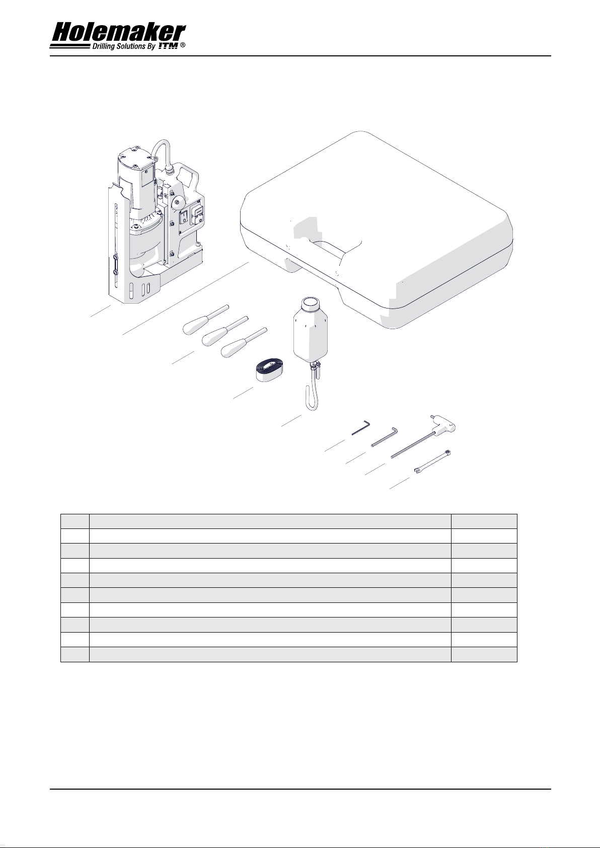
1.3. Equipment included.......................................................................................... 4
1.4. Dimensions ...................................................................................................... 5
1.5. Design.............................................................................................................. 6
2. SAFETY PRECAUTIONS ................................................................................ 7
3. STARTUP AND OPERATION.......................................................................... 9
3.1. Installing the handles ....................................................................................... 9
3.2. Installing the tools ........................................................................................... 10
3.3. Installing and removing the drilling chuck (option) .......................................... 11
3.4. Installing and removing the cooling system .................................................... 12
3.5. Monitoring system of the clamping force......................................................... 13
3.6. Preparing......................................................................................................... 13
3.7. Drilling ............................................................................................................. 15
3.8. Adjusting the gibs............................................................................................ 17
3.9. Replacing the brushes .................................................................................... 18
4.0. Parts List ......................................................................................................... 19

HMPRO55 OPERATOR’S MANUAL HMPRO55 OPERATOR’S MANUAL
2www.itmtools.com.au www.itmtools.com.au 3
PRO-55TCT
This document is protected by copyrights.
Copying, using, or distributing without permission of PROMOTECH is prohibited.
3
1. GENERAL INFORMATION
1.1. Application
The PRO 55 is a drilling machine designed to drill holes with diameters of up to 55
mm by using annular cutters. The machine can also drill holes with diameters of up to
18mm by using twist drill bits. It also allows machining holes with diameters of up to
55 mm by using countersinks.
The electromagnetic base clamps the machine to ferromagnetic surfaces. This
makes sure that the operator is safe and the machine works correctly. A safety strap
protects the machine from falling in case of a clamping loss.
Accessories allow you to drill in pipes and clamp the machine to flat non-
ferromagnetic surfaces.
1.2. Technical data
Voltage
1~ 220–240 V, 50–60 Hz
1~ 110–120 V, 50–60 Hz
Power
1100 W
Spindle shank
19 mm (3/4″) Weldon
Tool holder
19 mm (3/4″) Weldon
Maximum drilling diameter with a TCT annular cutter
55 mm
Maximum drilling diameter with a HSS annular cutter
55 mm
Maximum drilling diameter with a twist drill bit
18mm
Maximum diameter of a hole to be machined with a countersink
55 mm
Maximum drilling depth
75 mm
Clamping force
(surface with the thickness of 25 mm and roughness R
a
= 1.25)
9900 N
Electromagnetic base dimensions
84 mm × 168 mm × 41.5 mm
Stroke
165 mm
Rotational speed with load
200 rpm
400 rpm
Minimum workpiece thickness
6 mm (0.24″)
Protection class
I
Protection level
IP 20
Noise level
More than 70 dB
Required ambient temperature
0–40°C (32–104°F)
Weight
15.5 kg

HMPRO55 OPERATOR’S MANUAL HMPRO55 OPERATOR’S MANUAL
4www.itmtools.com.au www.itmtools.com.au 5
PRO-55TCT
This document is protected by copyrights.
Copying, using, or distributing without permission of PROMOTECH is prohibited.
4
1.3. Equipment included
1
Drilling machine
1 unit
2
Plastic box
1 unit
3
Handle
3 units
4
Safety strap
1 unit
5
Cooling system
1 unit
6
2.5 mm hex wrench
1 unit
7
5 mm hex wrench
1 unit
8
5 mm hex wrench with a handle
1 unit
9
8 mm combination wrench
1 unit
–
Operator’s manual
1 unit
6
7
8
9
5
4
3
1
2

HMPRO55 OPERATOR’S MANUAL HMPRO55 OPERATOR’S MANUAL
4www.itmtools.com.au www.itmtools.com.au 5
PRO-55TCT
This document is protected by copyrights.
Copying, using, or distributing without permission of PROMOTECH is prohibited.
5
1.4. Dimensions
331 mm (13″)
254 mm (10″)
409–574 mm

HMPRO55 OPERATOR’S MANUAL HMPRO55 OPERATOR’S MANUAL
6www.itmtools.com.au www.itmtools.com.au 7
PRO-55TCT
This document is protected by copyrights.
Copying, using, or distributing without permission of PROMOTECH is prohibited.
6
1.5. Design
Chip guard
Electromagnetic base
Hole for a safety strap
Electromagnetic base
(MAGNET) switch
Carrying handle
Motor START
Motor STOP
Gear switch
Feed shaft
Gib
Bottle valve lever
Spindle
with arbor

HMPRO55 OPERATOR’S MANUAL HMPRO55 OPERATOR’S MANUAL
6www.itmtools.com.au www.itmtools.com.au 7
PRO-55TCT
This document is protected by copyrights.
Copying, using, or distributing without permission of PROMOTECH is prohibited.
7
2. SAFETY PRECAUTIONS
1. Before use, read this operator’s manual and complete a training in occupational
safety and health.
2. Use only in applications specified in this operator’s manual.
3. Make sure that the machine has all parts and they are genuine and not damaged.
4. Make sure that the specifications of the power source are the same as those
specified on the rating plate.
5. Connect the machine to a correctly grounded power source. Protect the power
source with a 16 A fuse for 230 V or a 32 A fuse for 115 V. If you are going to work
on building sites, supply the machine through an isolation transformer with class II
protection only.
6. Set the MAGNET switch to ‘O’ before you move the machine. Use carrying handle
to move the machine.
7. Do not carry the machine by the power cord and do not pull the cord. This can
cause damage and electric shock.
8. Keep untrained bystanders away from the machine.
9. Before each use, ensure the correct condition of the machine, power source,
power cord, plug, control panel, and tools.
10. Before each use, make sure that no part is cracked or loose. Make sure to main-
tain correct conditions that can have an effect on the operation of the machine.
11. Keep the machine dry. Do not expose the machine to rain, snow, or frost.
12. Do not stay below the machine that is put at heights.
13. Keep the work area well-lit, clean, and free of obstacles.
14. Make sure that the tool is correctly attached. Remove wrenches from the work
area before you connect the machine to the power source.
15. Do not use tools that are dull or damaged.
16. Unplug the power cord before you install and remove tools. Use protective gloves
to install and remove tools.
17. Unplug the power cord before you manually turn the spindle.
18. Use annular cutters without the pilot pin only when you drill incomplete through
holes.
19. Do not drill/machine holes whose diameter or depth differ from those specified in
the technical data.
20. Do not use in explosive environments or near flammable materials.

HMPRO55 OPERATOR’S MANUAL HMPRO55 OPERATOR’S MANUAL
8www.itmtools.com.au www.itmtools.com.au 9
PRO-55TCT
This document is protected by copyrights.
Copying, using, or distributing without permission of PROMOTECH is prohibited.
8
21. Do not use on surfaces that are rough, not flat, not rigid, or have rust, paint,
chips, or dirt.
22. Do not use if the gibs are adjusted incorrectly.
23. Do not use if there is no grease on the gibs.
24. Do not use the gear switch if the motor is on.
25. Use the safety strap to attach the machine to a stable structure. Put the strap
through the hole in the machine body. In the horizontal position, attach the strap
to the carrying handle. Do not put the strap into the buckle from the front.
26. Use eye and ear protection and protective clothing. The clothing must not be loose.
27. We do not recommend work on workpieces thinner than 6 mm (0.24″). The clamp-
ing force depends on the workpiece thickness and is much lower for thin plates.
28. Each time before you put the machine on the workpiece, rub the workpiece with
coarse-grained sandpaper. Make sure that the full bottom of the base touches
the workpiece.
29. Do not touch chips or moving parts. Do not let anything catch in moving parts.
30. After use, clean the machine and the tool. Do not remove chips with bare hands.
31. Unplug the power cord before you do maintenance or install/remove parts.
32. Repair only in a service center appointed by the seller.
33. If the machine falls, is wet, or has any damage, stop the work and immediately
send the machine to the service center for check and repair.
34. Do not leave the machine when it operates.
35. If you are not going to use the machine, remove the tool from the holder. Then,
remove the machine from the work area and keep it in a safe and dry place.
36. If you are not going to use the machine for an extended period, put anti-corrosion
material on the steel parts.

HMPRO55 OPERATOR’S MANUAL HMPRO55 OPERATOR’S MANUAL
8www.itmtools.com.au www.itmtools.com.au 9
PRO-55TCT
This document is protected by copyrights.
Copying, using, or distributing without permission of PROMOTECH is prohibited.
9
3. STARTUP AND OPERATION
3.1. Installing the handles
Attach the handles to the feed shaft. You can install the shaft so that the handles are
on the opposite side of the machine. To do this, continue in the sequence that follows.
Make sure that the shaft is engaged with the rack (4).
3
1
2
5
4

HMPRO55 OPERATOR’S MANUAL HMPRO55 OPERATOR’S MANUAL
10 www.itmtools.com.au www.itmtools.com.au 11
PRO-55TCT
This document is protected by copyrights.
Copying, using, or distributing without permission of PROMOTECH is prohibited.
10
3.2. Installing the tools
Unplug the power cord and lift the chip guard (1). Turn the handles to the right (2) to
lift the motor. Use gloves to put the correct pilot pin into the annular cutter (3). Use a
dry cloth to clean the spindle and the cutter. Put the cutter (twist drill bit or counter-
sink) into the spindle (4) so that the flat surfaces (5) align with the screws (6). Use the
5 mm hex wrench to tighten the screws.
To remove the tool, loosen the screws (5) with the 5 mm hex wrench.
3
4
6
5
1
2

HMPRO55 OPERATOR’S MANUAL HMPRO55 OPERATOR’S MANUAL
10 www.itmtools.com.au www.itmtools.com.au 11
PRO-55TCT
This document is protected by copyrights.
Copying, using, or distributing without permission of PROMOTECH is prohibited.
11
3.3. Installing and removing the drilling chuck (option)
Unplug the power cord and lift the chip guard (1). Turn the handles to the right (2) to
lift the motor. Attach the adapter to the drilling chuck (3). Use a dry cloth to clean the
spindle and the chuck. Then, put the chuck into the spindle (4) so that the flat surfac-
es (5) align with the screws (6). Use the 5 mm hex wrench to tighten the screws. Put
the twist drill bit into the chuck (7).
To remove the chuck, loosen the screws (6) with the 5 mm hex wrench.
3
4
6
5
1
7
2

HMPRO55 OPERATOR’S MANUAL HMPRO55 OPERATOR’S MANUAL
12 www.itmtools.com.au www.itmtools.com.au 13
PRO-55TCT
This document is protected by copyrights.
Copying, using, or distributing without permission of PROMOTECH is prohibited.
12
3.4. Installing and removing the cooling system
Put the bottle on the screws (1). Attach the hose to the fitting (2).
To remove the bottle, continue in reverse sequence.
1
2

HMPRO55 OPERATOR’S MANUAL HMPRO55 OPERATOR’S MANUAL
12 www.itmtools.com.au www.itmtools.com.au 13
PRO-55TCT
This document is protected by copyrights.
Copying, using, or distributing without permission of PROMOTECH is prohibited.
13
3.5. Monitoring system of the clamping force
The drilling machine has a system that monitors the clamping force of the electro-
magnetic base. The force will be lower if there is rust, paint, chips, or dirt. The force
will be lower also if the surface is thin, rough, not flat, not rigid, the voltage is lower
than required, or the bottom of the base is worn.
If the clamping force is too low, the system will not allow the machine to operate.
Then, after you release the green MOTOR button, the motor stops. This happens on
a surface thinner than 5 mm (0.2″). The clamping force is then only about 25% of the
force that you can get on a flat plate that is 25 mm (1″) thick. To drill on thin plates
then, press and hold the green MOTOR button.
3.6. Preparing
Before use, clean steel parts, including the spindle, from anti-corrosion material used
to preserve the machine for storage and transport.
Attach the handles to the feed shaft. You can install the shaft so that the handles
are on the opposite side of the machine.
Apply a thin layer of grease to the gibs.
Select the tool that matches the required hole diameter. Use a dry cloth to clean
the spindle and the tool. Then, install the tool as described before.
Put the machine on a flat ferromagnetic surface with the thickness of at least
6 mm (0.24″). Make sure that there is no rust, paint, chips, or dirt. They decrease the
clamping force. The force will be lower also if the surface is thin, rough, not flat, not
rigid, the voltage is lower than required, or the bottom of the base is worn.
Connect the machine to the power source. Set the MAGNET switch to ‘I’ to turn
on the clamping. Some types of steel (non-ferromagnetic) do not conduct magnetic
flux so the machine cannot clamp onto them.
Use the safety strap to prevent fall and injury if the machine loses the clamping.
Attach the machine to a stable structure by putting the strap through the hole in the
machine body. In the horizontal position, attach the strap to the carrying handle.
Make sure that the strap is tight and not twisted. If the machine comes loose from the
workpiece and hangs on the strap, replace the strap. Do not put the strap into the
buckle from the front.

HMPRO55 OPERATOR’S MANUAL HMPRO55 OPERATOR’S MANUAL
14 www.itmtools.com.au www.itmtools.com.au 15
PRO-55TCT
This document is protected by copyrights.
Copying, using, or distributing without permission of PROMOTECH is prohibited.
14
Turn the handles to the left to put the tool tip above the workpiece.
For vertical drilling with an annular cutter, install the cooling system and fill it with
coolant. Do not use only water as the coolant. But you can mix water and drilling oil.
Then, make sure that the cooling system works correctly. To do this, lightly loosen
the bottle cap and use the lever to open the valve. Then, turn the handles to the left
to apply a light pressure on the pilot pin. The coolant should fill the system and start
flowing from the cutter.
The cooling system works by gravity. Thus, in the horizontal position, turn the bottle.
In the inverted position, use coolants under pressure or in the form of spray or paste.
Vertical drilling
Inverted drilling
Horizontal drilling
INCORRECT
CORRECT ✓

HMPRO55 OPERATOR’S MANUAL HMPRO55 OPERATOR’S MANUAL
14 www.itmtools.com.au www.itmtools.com.au 15
PRO-55TCT
This document is protected by copyrights.
Copying, using, or distributing without permission of PROMOTECH is prohibited.
15
3.7. Drilling
Set the speed based on the table that follows.
Tool
Hole diameter Rotational
speed*
[rpm]
Gear switch
setting
[mm] [in]
HSS annular cutter
12–19 0.47–0.75 400
20–40 0.79–1.57 200
TCT annular cutter
12–22 0.47–0.87 400
23–45 0.91–1.77 200
Twist drill bit
1.5–13 0.06–0.51 400
14–16 0.55–0.63 200
* For a sharp tool and mild steel with a strength Rm< 500 N/mm2(70,000 psi), such as St0 (S185), St3S
(S235JR), or St4W (S275JO).
Steel with a strength Rm≥500 N/mm2(70,000 psi), such as St5 (E295), 18G2A
(S355N), or 45 (C45), requires lower speeds. If the speed is too high or too low for
the workpiece strength and the type/diameter of the tool, the tool will wear faster or
be unable to drill the hole.

HMPRO55 OPERATOR’S MANUAL HMPRO55 OPERATOR’S MANUAL
16 www.itmtools.com.au www.itmtools.com.au 17
PRO-55TCT
This document is protected by copyrights.
Copying, using, or distributing without permission of PROMOTECH is prohibited.
16
Press the green MOTOR button to start the motor. Turn the handles to the left to
put the tool into the workpiece.
When the annular cutter goes through the workpiece, the slug
core is pushed out with a large force.
When you use an annular cutter, drill only through holes. For incomplete through
holes do not use the pilot pin.
Keep the machine in the same position until the hole is made.
If you are going to drill holes deeper than 50 mm (2″), retract the tool from the
workpiece as often as possible. This allows chips to be removed from the hole. If the
grooves of the tool are clogged, turn off the motor and use a brush to clean them.
After you get to the depth of 40 mm (1.6″), retract the tool from the workpiece as
often as possible. Then, manually apply the coolant from the bottle into the drilling area.
After the hole is made, retract the tool from the workpiece, and press the red
MOTOR button to turn off the motor. Before you move the machine, set the MAGNET
switch to ‘O’ to turn off the base.
After the work is finished and the motor turned off, set the gear switch to the
opposite position. Then, turn on the motor and let it operate for a while with no load
to improve lubrication. Next, turn off the motor and the base, and then unplug the
power cord. Clean the machine and the tool, and then remove the machine from the
work area.
Incomplete through holes
Complete through holes

HMPRO55 OPERATOR’S MANUAL HMPRO55 OPERATOR’S MANUAL
16 www.itmtools.com.au www.itmtools.com.au 17
PRO-55TCT
This document is protected by copyrights.
Copying, using, or distributing without permission of PROMOTECH is prohibited.
17
Tighten the bottle cap, close the valve, and then press the pilot pin to remove the
coolant that remains in the cooling system. Before you put the machine into the box,
remove the bottle, and use gloves to remove the tool from the holder.
3.8. Adjusting the gibs
Every 50 work hours, make sure that the gibs are correctly adjusted. To do this,
move the motor up and down and make sure that it moves smoothly.
To adjust the gibs, apply a thin layer of grease on them. Then, use the 8 mm
combination wrench, the 2.5 mm hex wrench, and the 5 mm hex wrench to loosen
the nuts and screws (1). Put the motor so that the slider is in the center of the gibs
(2). Then, lightly tighten the screws (3) so that they touch the gib. Move the motor up
and down and adjust the screws (3) so that the travel is smooth. Next, tighten the
screws (4) and then tighten the nuts (5).
1
2
3
4
5

HMPRO55 OPERATOR’S MANUAL HMPRO55 OPERATOR’S MANUAL
18 www.itmtools.com.au www.itmtools.com.au 19
PRO-55TCT
This document is protected by copyrights.
Copying, using, or distributing without permission of PROMOTECH is prohibited.
18
3.9. Replacing the brushes
Every 100 work hours, check the condition of the brushes. To do this, unplug the
power cord and remove the cover (1). Lift the spring (2) and remove the brush. If the
brush is shorter than 5 mm (0.2″), replace the two brushes with new ones.
Install in reverse sequence. Then, let the motor operate with no load for
20 minutes.
1
2

HMPRO55 OPERATOR’S MANUAL HMPRO55 OPERATOR’S MANUAL
18 www.itmtools.com.au www.itmtools.com.au 19
Parts list v.0.04
This document is protected by copyrights.
Copying, using, or distributing without permission of PROMOTECH is prohibited. 2
7
1
6
8
5
3
2
4
ITEM
PART NUMBER
DESCRIPTION
QTY
1
SKR-000028
PLASTIC BOX
1
2
DZW-0212-12-00-00-1
SPOKE HANDLE ASSY
3
3
KLC-000005
2,5 HEX WRENCH
1
4
KLC-0565-08-00-00-0
5 HEX WRENCH
1
5
KLC-000003
8 COMBINATION WRENCH
1
6
KLC-000037
5 MM HEX WRENCH WITH HANDLE
1
7
PAS-000008
SAFETY STRAP
1
8
UKL-0716-04-00-00-0
COOLING SYSTEM
1
*not shown in the drawing
4.0. PARTS LIST

HMPRO55 OPERATOR’S MANUAL HMPRO55 OPERATOR’S MANUAL
20 www.itmtools.com.au www.itmtools.com.au 21
Parts list v.0.04
This document is protected by copyrights.
Copying, using, or distributing without permission of PROMOTECH is prohibited. 3
15
28
4
56
25
26
7
8
9
16
14
32
29
27
24
17
30
18
12
23
19
13
11
20
10
2
1
22
21
31
3
ITEM
PART NUMBER
DESCRIPTION
QTY
1
NPD-0716-02-00-00-0
MOTOR ASSY – 230V
1
2
PWD-0684-03-02-00-1
MOTOR WIRE ASSY
1
3
WKR-000395
HEX SOCKET ROUND HEAD SCREW WITH FLANGE
2
4
PDK-000151
NYLON WASHER 8,1x14x3
4
5
SPR-000030
SPRING 1x10x17.5
2
6
TLJ-0399-06-00-00-0
BOTTOM SLEEVE
2
7
WKR-000415
HEX SOCKET ROUND HEAD SCREW WITH FLANGE 3,5x13
8
8
PDK-000161
EXTERNAL TOOTH LOCK WASHER 3.7
8
9
SCN-0716-06-00-00-0
BODY COVER
1
10
SRB-000304
HEX SOCKET HEAD CAP SCREW M6x20
8
11
PDK-000136
ROUND WASHER 6,4
8
12
LST-0331-01-05-00-0
GIB
1
13
LST-0331-01-04-00-0
ADJUSTABLE GIB
1
14
PDK-00004
SPRING WASHER 6.1
4
15
SRB-000117
HEX SOCKET HEAD CAP SCREW 6x25 Zn
2
16
PDS-0716-03-00-00-0
ELECTROMAGNETIC BASE ASSY
1
17
WZK-0242-04-00-00-0
REED WIRES SET
1
18
FLT-0257-04-12-00-0
INTERFERENCE ELIMINATOR
1
19
STR-0257-04-03-00-2
MODULE - 230V
1
20
MSK-0716-05-01-00-0
PANEL PLATE
1
This manual suits for next models
1
Table of contents
Other Itm Drill manuals

Itm
Itm TGMD400 User manual

Itm
Itm TD1420F User manual

Itm
Itm HOLEMAKER HMPRO35-T3 User manual

Itm
Itm HOLEMAKER PRO 35 User manual

Itm
Itm HOLEMAKER HMPRO200A User manual

Itm
Itm HOLEMAKER PRO 52-MT2 User manual

Itm
Itm Holemaker HMP45 User manual

Itm
Itm HOLEMAKER HMPRO36AD User manual

Itm
Itm TGD400 User manual

Itm
Itm HOLEMAKER PRO 35 User manual