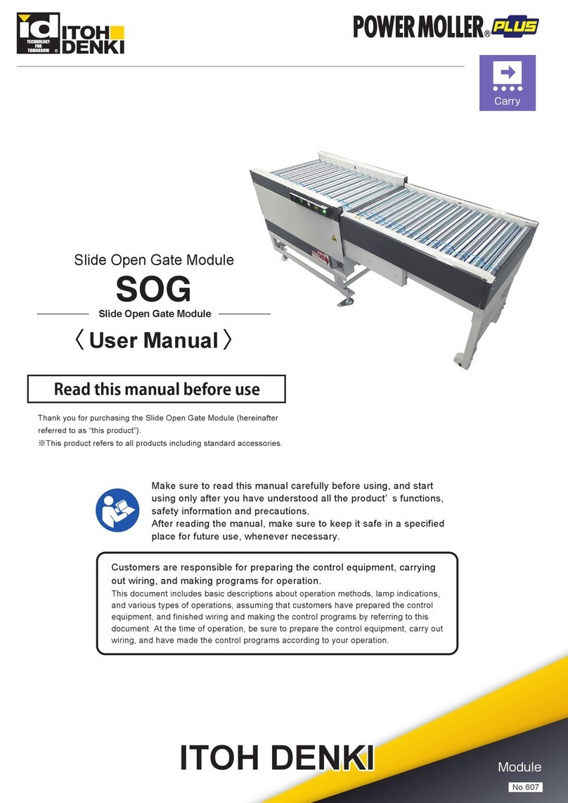
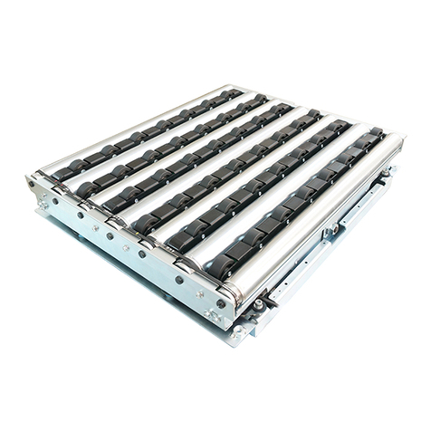
ITOH DENKI POWER MOLLER PLUS F-RAT-NX75 User manual

1
Thank you for purchasing the Right-Angle Transfer Module
(hereinafter referred to as “this product”).
Make sure to read this manual carefully before using, and start
using only after you have understood all the product’ s functions,
safety information and precautions.
After reading the manual, make sure to keep it safe in a specified
place for future use, whenever necessary.
ITOH
Module
No.516
Right Angle Transfer Module
F-RAT-NX75
Flat-Right Angle Transfer
Read this manual before use

Features
2
F-RAT-NX75 User Manual
Features Features of this product
・
This product is a module to divert at a right angle without changing its level, and
there is no impact on the trays.
・
All-electric control. No pneumatics, which do not require compressor.
Operation description
(when diverting at a
right angle)
Load
Switch to the diverting
direction
Discharge
Switch to the straight
direction

3
Disclaimer
Notes on industrial
property rights
This product is designed as a general industrial device. Do not use for other
applications. We do not take any responsibility for any damage that may result from the
disregarding of these warnings.
Also, in the event that an accident results from the use of this product, we do not
compensate for any damage, including abnormalities of equipment, connection
devices, and/or software, any damage resulting from malfunctions, and/or any other
secondary damage.
There are some examples of parts thatneed to be prepared by customers, as explained
within this manual. However, this does not provide any guarantee against the existence
of any rights, such as our industrial property rights, or those of other companies, in
advance.
Notes on technical
support We respond to technical inquiries based on the contents described within this manual,
and on this product within the range of general items for this product unit with standard
specifications, and for the options prepared by us.
There are some descriptions in this manual, about parts, equipment, and wiring
arranged by customers, as well as the controls and operation under such
circumstances. However, these are not included in the guaranteed operating range
and/or support.
When in use, please check and perform the aforementioned based on your
responsibility according to operation.
About the risk category
of this system This product is intended to comply with the risk category 2*2or lower as defined in
EN954-1*1. It does not comply with purposes beyond risk category 3 or higher.
*1: European machinery safety standards
*2: This indicates that even though events that would result in serious injury occur infrequently under
assumed risk environment, there is a high probability to avoid danger if you observe the safety
contents described in this manual.
About installation
environment This product is not equipped with special dust proof/waterproof countermeasures, and
is intended to be used in environments of “Pollution Degree 2”, as defined in IEC60664-
1.
For these reasons, if users install this product in an environment that requires dust
proof/waterproof treatments, they need to add necessary countermeasures, and
check the performance based on their responsibility.
About description of
the product
・
In this manual, F-RAT-NX75 is described as F-RAT, and F-RAT-NX75 and F-RAT
are described separately, when needed.
・
Depending on the signal type(NPN/PNP) specified by customers, different models
of control driver cards are supplied as being the standard for this product.
Driver cards purchased
separately
NPN/PNP must be
specified
CB series
IB series
(1) CBK-109F_
(2) CB-016B_
(1) IB-E04F-_
(1) IB-E03B-_
In this manual, CBK-109FN and CBK-109FP are described as CBK-109, CB-016BN6 and
CB-016BP6 as CB-016.
Also, CBK-109FN and CBK-109FP, CB-016BN6 and CB-016BP6 are described separately, when
needed.
1.Introduction

Proceduresfrominstallationtooperation
F-RAT-NX75 UserManual
4
Prepare the 24V DC power supply, such as DC power supply units.
Prepare control devices, such as PLCs.
P.14 ~
Open the package, and check the model, specifications, voltage, etc.
Check accessories.
P.24 ~
Perform control (programming).
P.42 ~
Perform inspection before operation.
P.46 ~
Install the F-RAT main unit.
P.36 ~
Procedures from
installation to operation
Read this manual
Advance preparation
Product check
Installation
Wiring
Control
Start-up inspection
Yes
Maintenance/Inspection
Troubleshooting
Start using only after you have understood all the product’ s functions, safety
information, and precautions.
Some errors have been found.
No
Perform maintenance and inspection
based on corresponding parts.
P.48 ~
Yes
Have the problems been solved? No
Take appropriate measures based
on the corresponding symptoms.
P.60 ~
Run operation.
Mount driver cards.
Connect the F-RAT and driver cards.
Connect power and signal cables to driver cards.
Perform settings of driver cards.
Connect to power supply units/PLCs.
P.41 ~

5
F-RAT-NX75 User Manual
INDEX 1. Introduction … 2
2. Procedures from installation to operation … 4
3. Safety precautions … 6
3-1. General precautions … 8
3-2. Precautions on installation … 10
3-3. Precautions on wiring … 11
3-4. Precautions related to control … 11
3-5. Precautions related to operation … 12
3-6. Precautions on maintenance and inspection … 12
4. Advance Preparation … 14
5. Product Check … 19
6. Structures … 22
7. Installation / Wiring … 24
7-1. Before installation … 25
7-2. Installation … 35
7-3. Wiring … 36
8. Control / Operation … 41
8-1. Basic operation … 42
8-2. Switching the transfer direction … 43
8-3. Changing the speed … 44
8-4. What to do before operation … 46
8-5. Timing Chart Example … 47
9. Maintenance / Inspection … 49
9-1. Driver card LED display and errors countermeasures … 50
9-2. Before replacement work … 52
9-3. Replacement of MDR for roller transfer/idlers/drive belts … 54
9-4. Replacement of the carrier wheel cassette … 59
10. Troubleshooting … 61
Appendix … 65
Appendix 1. Product specifications … 66
Appendix 2. Replacement parts / Options … 69
Appendix 3. Residual risk list …70
INDEX

6
F-RAT-NX75 User Manual
For parts names in sentences, refer to 6. Structures (P.21).
3-1.
General precautions
…… 8
3-2.
Precautions on installation
…… 10
3-3.
Precautions on wiring
…… 11
3-4.
Precautions related to control
…… 11
3-5.
Precautions related to operation
…… 12
3-6.
Precautions on maintenance and inspection
…… 12
3. Safety precautions

Danger level
3. Safety precautions
F-RAT-NX75 UserManual
7
Danger level
Symbol explanation
To prevent hazards to users and/or others, and/or damage to property in advance, the
important precautions to be followed securely is described below.
■The degree of hazard and/or damage that may result if a user disregards the
description and operates the product improperly is categorized by the following
symbols and explained below.
WARNING
This indicates a high possibility that severe injury or
even death may result.
CAUTION
This indicates a high possibility that injury, or only
property damage may result.
■The type of precautions is categorized as the following symbols and explained
below.
Thissymbolindicatesareminderwhichusersshouldpay
attention to.
This symbol indicates operations that are prohibited.
This symbol indicates forced operations that users should
always perform.

General precautions
F-RAT-NX75 UserManual
8
3-1.
General precautions
Do not use the product near places subject to explosive,
flammable gas, and/or corrosive atmosphere, and/or
combustible materials.
Failure to follow this could result in explosion, fire, electric shock and/or
injury.
When using the product in places where serious accidents
and/or damage may possibly occur, install backup and/or
fail-safe functions systematically.
Failure to follow this could result in the inability to control this product due
to driver card malfunction, which could lead to serious accidents.
Do not apply heavy loads to this product, such as stepping on it.
Failure to follow this could result in people falling and/or malfunction.
Do not come into contact with the moving parts, such as the
carrier wheels, rollers, or lifting sections, and/or allow clothes to
get close tothem.
Failure to follow this could result in them getting caught and/or stuck.
Do not forcibly bend and/or pull cables.
Also, do not put heavy materials on cables, or do not get them
stuck betweencables.
Failure to follow this could result in fire and/or electric shock due to cable
damage.
Never remodel the product and/or driver cards.
Failure to follow this could result in serious accidents.
Make sure to attach ground wires to this product and the DC
power supplyunit.
Failure to follow this could result in electric shock if any malfunction or leakage
occurs.
Do not touch the product when it has just stopped operation.
Failure to follow this could result in burns.
Do not put water and/or oil on the product, and do not transfer
wet and/or oilytrays.
Failure to follow this could result in electric shock, and/or malfunction.
Do not apply strong impact and/or excessive force to the
product, such as hitting it with objects, or dropping it. Also, do
not use the equipment if strong impact has been applied, and/or
if the appearance has become deformed.
Failure to follow this could result in malfunction due to applied impact.
3. Safety precautions
WARNING
CAUTION

General precautions
F-RAT-NX75 UserManual
9
3-1.
General precautions
Stop operation when abnormal sound is heard during operation.
Failure to follow this could result in unexpected accidents.
Do not use in a way exceeding the range of the product
specifications.
Failure to follow this could result in malfunction, fire, and/or injury.
Turn off the power supply to the product before moving and/or
installing the product, and performing maintenance and
inspection (excluding those during operation).
Working while the power is oncould result in accidents due to unexpected
operation.
Observe the safety regulations required for installation locations,
and/or products in use.
Securely wire each cable to connection parts.
Improper wiring could result in electric shock and/or malfunction.
Do not turn on/off relays and/or contactors near power cables,
signal cables, and/or driver cards.
Failure to follow this could result in malfunction due to noise generation.
LED or Pull-up/Pull-down circuits implemented in the output
circuit of control devices could result in unexpected operation.
Carefully check the output circuit.
Turn on the power in order of external control devices, and then
the product.
Turn off the power in order of the product, and then external
control devices.
Turning on/off the power in the wrong order could result in malfunction.
Do not unplug power and/or signal cables during operation.
Also, do not run/stop this product by the power supply.
(Use thesignal.)
Failure to follow this could result in malfunction.
Do not forcibly rotate the MDR at times other than maintenance
and inspection.
Failuretofollowthiscould result in damage todrivercards, and/or their lifetime
to be significantlyshortened.
Do not turn off the power during transfer (during MDR rotation).
Failure to follow this could result in malfunction.
3. Safety precautions
CAUTION

Precautions on installation
3. Safety precautions
F-RAT-NX75 UserManual
10
3-1.
General precautions
Do not turn on the power when trays are unstable.
Failuretofollowthiscouldresultin injury, accidents, and/or damage duetoload
collapse.
Make sure to perform the start-up inspection, and check that
devices are free from any abnormalities, and that safety
equipment functions correctly before using the product.
When disposing of the product, make consigning contracts with
licensed industrial waste disposers, and consign the disposal to
them.
3-2.
Precautions on
installation
In principle, have two or more persons work when carrying
and/or installing the product as it is a heavy load.
When hoisting this product, never enter the area under the
suspended load.
When hoisting, use appropriate hoisting equipment, and pay special
attention to prevent the balance of the suspended load from being lost
and/or falling. Also, have only qualified workers conduct the operation.
Improper hoisting could result in serious accidents.
Do not hoist this product with goods loaded.
Failure to follow this could result in objects falling.
When handling, wear protective equipment, such as gloves.
Since this product consists in large part of metal, careless handling could result
in hands getting injured.
Make sure to use the recommended tightening torque to tighten
bolts for installing the F-RAT main unit and/or fastening screws of
driver cards.
Failure to follow this could result in bolts and/or screws loosening, and/or
malfunction.
Check the corresponding installing direction to the
loading/discharging sides before installing.
Failure to follow this could result in objects/body parts getting caught and/or
stuck.
WARNING
CAUTION
CAUTION

Precautions on wiring
3. Safety precautions
F-RAT-NX75 UserManual
11
3-2.
Precautions on
installation
Take appropriate measures to prevent trays from popping out of
the equipment.
For example, mount guide rails on the conveyor frames.
Failure to follow this could result in workers getting injured by trays popping out of
the equipment.
If necessary, warning/caution labels become hidden after
installing fences, affix again on places where they can be seen.
3-3.
Precautions on wiring
Perform wiring when the power is shut off.
Failuretofollow this could result in electricshock and/oraccidents dueto
unexpected operation.
When attaching or removing connectors, turn off the power first,
securely hold connectors, and perform operation.
Also, do not apply excessive force to the driver card connection
parts, such as obliquely attaching or removing connectors.
Failuretofollowthiscouldresultin electricshock,malfunction,and/oraccidents
due to unexpectedoperation.
Securely attach connectors to the driver card connection parts.
Improper wiring could result in electric shock and/or malfunction.
Perform wiring to connectors so that cables make secure contact
with connectors.
Barb linesfromthecable core could result in heat generation and/or fire dueto
changes of contact resistance, and/or short circuit with the adjacent contact.
3-4.
Precautions related to
control
Do not change the VR1 and VR2 values on CBK-109 and CB-016.
(Minimum (leftmost): Factory setting)
Do not turn the driver card switches with excessive force.
Failure to follow this could result in malfunction.
CAUTION
CAUTION
CAUTION

Precautions related to operation
3. Safety precautions
F-RAT-NX75 UserManual
12
3-5.
Precautions related to
operation
Do not forcibly move trays when they are placed on the carrier
wheels.
Failure to follow this could result in damage and/or malfunction.
Make sure to perform the start-up inspection before starting
operation.
At the start-up inspection, wear protective equipment, such as
gloves.
Failure to follow this could result in hands getting injured by metal parts.
At the start-up inspection, shut off the power, and perform
inspection.
(excluding inspection to be performed when operating this product.)
Failure to follow this could result in injury due to unexpected operation, such as
getting caught and/orstuck.
When operating this product at the start-up inspection, take
appropriate measures to prevent fingers from getting stuck
and/or caught in carrier wheels and/or rollers.
Also, get ready to shut off the power in the event that something
should happen.
Failuretofollowthiscouldresultin accidents/injury by gettingcaught and/or
stuck.
If any abnormalities are found at the start-up inspection, make
sure to take countermeasures before the trial run.
Failure to follow this could result in damage and/or malfunction.
3-6.
Precautions on
maintenance and
inspection
If any abnormalities are found, do not use this product until the
causes have been eliminated completely.
Usingthis productwith unattended abnormalitiescouldresult in not only
damage to the devices, but also unexpected accidents.
Have specialists (or people who have sufficientlyacquired skills)
perform maintenance and inspection under instructions by
management supervisors.
At the time of repair and replacement work, turn off the power to
all connecting devices.
Toprevent wraparoundforthepowercircuits and/or signals, shut offthepower,
wait asufficient amount of time, and discharge electricity inside the DC power
supply equipment.
At the time of maintenance and inspection, post warning labels
so as to prevent unauthorized persons from turning on the power.
Failure to follow this could result in malfunction and/or unexpected accidents.
CAUTION
CAUTION

Precautions on maintenance and inspection
F-RAT-NX75 UserManual
13
3-6.
Precautions on
maintenance and
inspection
When repairing/replacing, wear protective equipment, such as
gloves.
Failure to follow this could result in hands getting injured bymetal parts.
Do not disassemble sections and/or parts other than those
specified.
Failure to follow this could result in malfunction and/or unexpected accidents.
Depending on sections and/or parts to be repaired and/or
replaced, they need to be rotated and/or lifted by hand.
Pay attention not to get caught and/or stuck. Failure to follow this could result in
injury.
Before the trial operation after repair/replacement,
· Check that the roller drive belts have been mounted properly.
· Check that there is no friction between the moving parts, or
between the moving and fixed parts.
· Check that screws/covers previously removed have been
securely mounted again.
· Check that all parts are installed.
Failure to follow this could result in malfunction and/or unexpected accidents.
Make sure to prepare repair/replacement parts designated by
ITOH DENKI.
Using parts other than those designated by ITOH DENKI could result in
malfunction.
3. Safety precautions
CAUTION

14
4. Advance preparation
F-RAT-NX75 UserManual
4.
Advance preparation

15
F-RAT-NX75 User Manual
Wiring image
【Important 】As for the sensor input, and input/output signals of driver cards,
adopt the number of inputs/outputs based on operation.
Emergency stop equipment
4. Advance preparation

16
F-RAT-NX75 UserManual
Items to be prepared
by customers
Before introducing this product, prepare the following devices separately.
Emergency stop
equipment This product does not include the emergency stop equipment.
Customers must make sure to install it.
Install the emergency stop equipment on the side of the DC power supply unit to
which the power is supplied.
Checking the breaker
Operation check
Regarding facilities where this product is incorporated, check that a breaker with
appropriate capacity for the 24V DC power supply unit has been installed. If abnormal
operation should occur, protection through the breaker could be effective.
Note that when using an earth leakage breaker, select one that is “inverter
corresponding”. Some inverter non-corresponding earth leakage breakers could result
in malfunction, since they may recognize high-frequency components of the switching
power supply as leakage.
When the 24V DC power supply unit has been incorporated, check that the breaker and
emergency stop switch can work properly. Perform operation following the trial
operation after checking them.
① Input to the DC power supply (single phase 100V/200V) is securely turned
ON/OFF when turning ON/OFF the breaker.
② Input to this product (24V DC) is securely turned ON/OFF when turning ON/OFF
the emergency stop switch.
4. Advance preparation
Emergency stop equipment

24V DC powersupply
F-RAT-NX75 UserManual
4. Advance preparation
17
24V DC power supply
Control devices
Sensors
Power supply equipment to supply 24V DC to this product
●Switching power supply (24V DC/10A, 240W or more)
●Rectified power (With a rectifying capacitor, ripple rate 10% or below)
●24V DC Battery
Devices to control this product, such as PLCs
Zone sensors to check the tray, and area sensors to check loading and discharging, etc.
Operation
■Since F-RAT uses MDR for each of carrier wheel transfer, roller transfer,
and drive switching (3 MDRs in total), it is not recommended to use
multiple MDRs at the same time.
Area sensor
(Discharge)
Area sensor
(Discharge)
F-RAT zone
sensor
Area sensor
(Load)
Transfer
direction
■
A switching power supply is recommended asthe DC power supply (24V
DC±10%) for drivers.
■Use a stabilized power supply that has an adequate capacity of 24V DC and
10A or higher and does not fluctuate due to loadvariation.
■The power supply shall have a capacity larger than the rated value of this
product.
■A transformer type power supply cannot be used.
■Secure a voltage of 24V DC±10% at the power supply terminal of a drivercard.
■If the capacity of the power supply is less than the rated power of this product,
it may cause the supply voltage leading malfunction or damage.
Be sure to use the power supply with a capacity larger than the rated power of
this product.
■In addition, the power supply should not activate protection with peak current
30A for 1ms or below.
■For the power supply unit, use an isolation type switching power supply
compliant with the safety standard (IEC60950-1 or UL60950-1). Do not use a
non-isolationtype power supply for safety reasons, since it may not conform to
the radiation noise regulations.
Zone sensor
A sensor to detect the existence of trays within the zone
Area sensor
Term A sensor to detect load and discharge of trays

MDR extension cable (option)
F-RAT-NX75 UserManual
4. Advance preparation
18
Wiring materials Necessary for wiring of power and signal cables, branch connectors, driver cards,
controllers, such as sensors or PLCs, and power supply.
〈
Available wire diameter for driver card connectors
〉
MDR extension cable
(option) Necessary when the installing location of the F-RAT main unit is far from that of the
driver cards.
■CBK-109:12P extension cable (Male side)
■CB-016 :10P extension cable (Male side) (Female side)
37
60 ±5
L
Power connector
Control connector AWG:28~20
CB-016
CBK-109
Connector
Driver card
Model Cable Length
M-F-EXT-12PIN-600 600 mm
M-F-EXT-12PIN-1200 1200 mm
Model Cable Length
M-F-EXT-10PIN-600 600 mm
M-F-EXT-10PIN-1200 1200 mm
■
To select the current capacity of wiring materials, secure a high safety margin
based on the current value in the equipment to be used.
■Longer wiring between the power supply unit and driver cards/controllers could
cause the voltage to decrease, resulting in malfunction and/ordamage.
(Female side)
■Use extension cables of 1200 mm or less.
■Do not extend cables by connecting multiple extension cables.
32.5
37.5

19
Product check
F-RAT-NX75 UserManual
5.
Productcheck

Checking the model
5. Product check
F-RAT-NX75 UserManual
20
Checking the model Unpack the product, and check that the product model is as ordered.
Checking appearance ①Check that the main unit is free from any abnormalities, such as traces of scratches,
dents, dirt, and/or corrosion (rust).
②Check that there is no omission and/or looseness of screws, etc.
*If any abnormalities are found, contact the supplier immediately.
Model
Other manuals for POWER MOLLER PLUS F-RAT-NX75
1
Table of contents
Other ITOH DENKI Control Unit manuals
Popular Control Unit manuals by other brands

DAV TECH
DAV TECH DA 400 EV Installation and maintenance guide

GE
GE 12000 Instructions for installation, use and maintenance

Toshiba
Toshiba Adjustable Speed Drive H7 Series specification

KSB
KSB Cervomatic EDP.2 Installation & operating manual

InSinkErator
InSinkErator MS MS installation manual

Aliaxis
Aliaxis FIP Dual Block VKDIC quick start guide