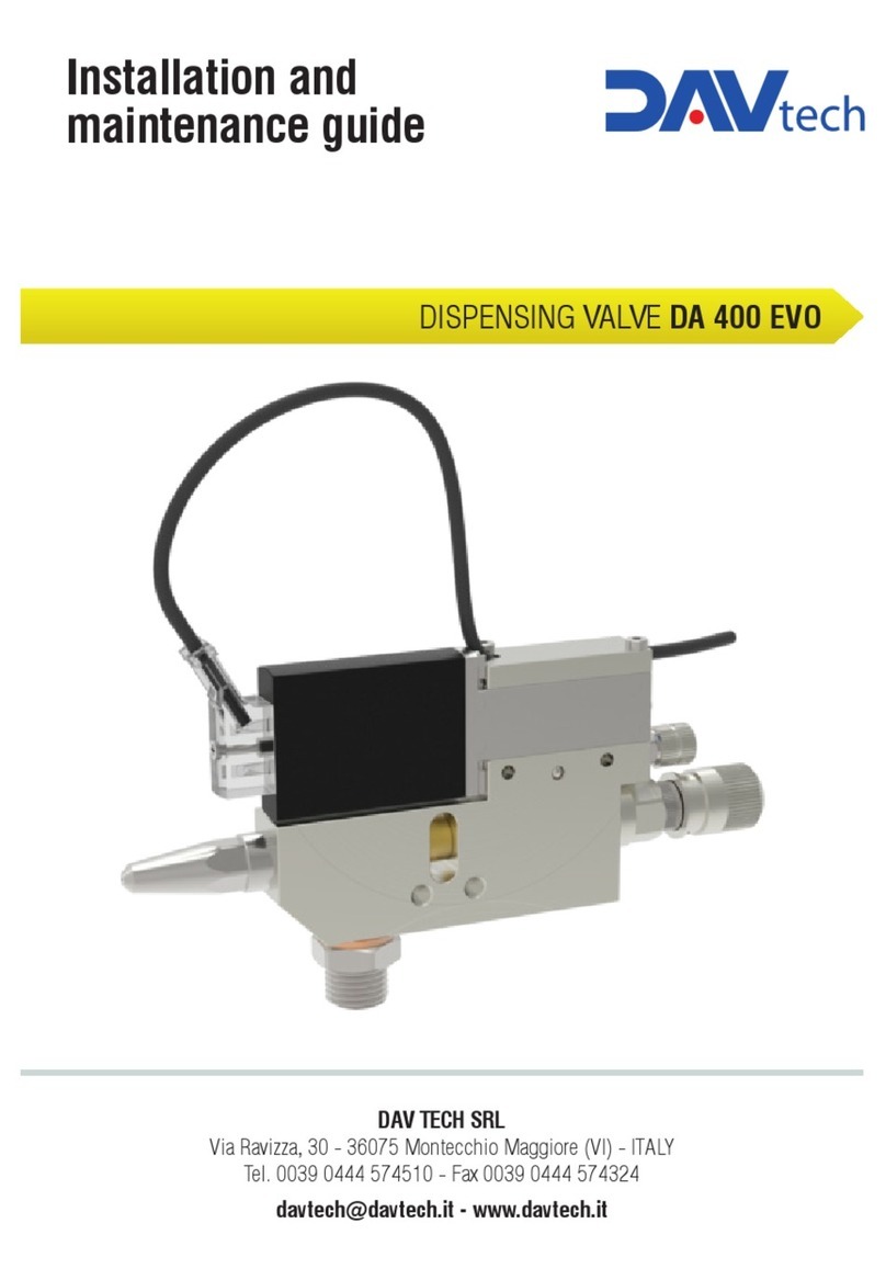
DAV TECH DA 400 EV Product manual

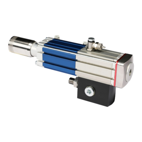
DISPENSING VALVE DA 400 EV
DAV TECH SRL
Via Ravizza, 30 - 36075 Montecchio Maggiore (VI) - ITALY
Tel. 0039 0444 574510 - Fax 0039 0444 574324
Installation and
maintenance guide

Index
1 INTRODUCTION pag. 3
1.1 The manual
1.2 Warranty
1.3 Goods receiving
2 TECHNICAL DESCRIPTION pag. 3
2.1 Valve operation
2.2 Technical specifications
2.3 Connection diagram
3 INSTALLATION pag. 4
3.1 Mounting on the machine
3.2 Drive the valve
3.3 Fluid connection
3.4 Setting of the valve
3.5 Setting of the material quantity
4 MAINTENANCE pag. 6
4.1 General rules
4.2 Valve disassembly
4.3 Re-assembly
5 TROUBLESHOOTING pag. 6
5.1 Problems and solutions
6 SPARE PARTS AND DIMENSIONS pag. 7
6.1 Overall dimensions
6.2 Spare parts DA 400 EV
6.3 Spare parts list DA 400 EV
Installation and maintenance guide

DISPENSING VALVE DA 400 EV
pag.3
1 INTRODUCTION
1.1 The manual
The user guide is the document that accompanies the valve from the time of its construction and throughout the period of
use, it is therefore an integral part of the valve. It requires reading the manual before taking any action involving the valve. The
manual must be readily available for use by staff and maintenance of the valve. The user and the attendant use are required
to know the contents of this manual.
Reproduction of any part of this manual, in any form, without the express written permission of DAV Tech. The text and
illustrations in this manual are not binding, the DAV tech reserves the right, at any time and without notice, the right to make
any changes to improve the product or for reasons of character manufacturing or commercial.
1.2 Warranty
The warranty is valid for a period of 12 months from the date of commissioning and no later than 15 months from the
date delivery. The interventions carried out during the warranty period does not extend in any way the validity period of the
guarantee. The seller is not liable for defects caused by normal wear of parts which by their nature are subject to wear.
1.3 Goods receiving
The original configuration of the valve must never be changed.
Upon receipt of the goods, check that:
• The packaging is intact
• The exact correspondence of the material ordered.
2 TECHNICAL DESCRIPTION
2.1 Valve Operation
The DA 400 EV dispensing valve is a pneumatic control component designed for precision dosing of low, medium or high
viscosity fluids. Its rest state is normally closed, presenting a safety spring inside it. The pneumatic supply, at a pressure equal
to or greater than 6 bar, together with the 24 VDC supply of the solenoid valve, causes the inside of the pin and the fluid to leak
back. Fluid bleeding can be modulated, as well as with the pressure to which it is supplied, by adjusting the needle opening by
adjusting the top of the DA 400 EV valve.
2.2 Technical Specification
Model DA 400 EV
Operation mode Double Acting
Weight 310 g
Max fluid pressure Max 80 bar
Actuating air pressure 6 - 7 bar
Air inlet thread M5
Fluid inlet thread 1/8 gas
Outlet Thread Threaded nozzles, luer lock thread, steel nozzles of various shapes and sizes
Speed Up to 300 cycles / min
Adjusting the passage With micrometric screw or with screw and nut
Used Materials Stainless steel, TCT, nickel plated brass and Teflon
Fluids to be used Silicones, liquid gaskets, greases, resins, various medium-high viscosity

2.3 Connection diagram
3 INSTALLATION
3.1 Mounting on the machine
The 400 EV valve can be mounted using the through holes on its body. If necessary, contact us and we will be happy to
provide you with the 3d models of the valve to design brackets, fasteners and check the dimensions.
3.2 Drive the valve
The 400 EV valve works at double acting by the solenoid valve 5/2 mounted directly on board.
The solenoid valve is always kept powered at a pressure of 6 bar upwards and commanded by giving and removing
24 VDC power.
We reserve the right to modify at any time, without notice, the specifications, dimensions and weights in this datasheet. The illustrations are not binding.
NOZZLES FOR DA 400 EV DISPENSING VALVE
The valve DA 400 EV presents a very high number of nozzles available as
standard. Nozzles with thread 1/8 BSP male, luer lock, nozzles complete
with various shapes and diameters from 0.3 to 1.5 mm. If necessary, we
can design and create multi-point terminals, with radial outlets, inclined etc.
DRIVE VALVE DA 400 EV
The valve has a 5/2 solenoid valve mounted directly on board, and it is therefore sufficient to feed the power supply
(24V) to the solenoid (which is always kept fed pneumatically to 6-7 bar) for controlling the dispensing.
Schema di Collegamento
• 0.3
• 0.5
• 0.8
• 1
• 1.5
LV
18SY MG
• 0.3
• 0.5
• 0.8
• 1
• 1.5
KV
• 0.3
• 0.5
• 0.8
• 1
• 1.5
KL
Valve configurations DA 400 EV_ _ _ _
Ø Ø Ø
NOZZLES AVAILABLE REGULATION
screw micrometric
RMNR
Special versions available on request.
mm mm mm
Connection diagram
PNEUMATIC PUMP
PRESSURE
STABILIZATOR
PLC
Installation and maintenance guide

pag.5
3.3 Fluid connection
The valve must be connected to a power supply unit (tank, pump or other). A hose must be connected to the fitting
located at the bottom of the valve. When working at pressures above 8 bar, use high pressure connections and tubes.
3.4 Setting of the valve
The adjustment of the stroke determines together with the pressure of the material
and at the opening time the amount of fluid dispensed.
> Screw Adjustment Version:
Unscrew the lock nut, located at the top of the valve, with a 10 wrench, adjust the
adjustment grain with a 3 - pole wrench.
Rotate clockwise to decrease the stroke and consequently the fluid flow. Turning
clockwise, reaching the end of the stroke the valve will be fully closed, so it will
not flow fluid. Rotate counterclockwise to increase the stroke and then the amount
of fluid. Determine the amount of product you want to tighten the lock nut with a
10-key.
> Micrometric adjustment version:
To adjust the travel, act on the adjustment knob at the top of the valve. Turn
clockwise to decrease spike stroke and consequently the amount of product.
Turning clockwise, reaching the end of the stroke the valve will be fully closed,
so it will not flow fluid. Rotate counterclockwise to increase the stroke and then
the amount of fluid.
3.5 Setting of the material quantity
Adjusting the amount of material is determined by:
> Nozzle diameter (0.3 - 0.5 - 0.8 - 1.0 - 1.5) except luer lock nozzles, threaded 1/8 or with nut
> Fluid pressure
> Adjusting the stroke of the needle
Acting on these factors, you can adjust the amount of material you want.
Material input
Do not tighten the needle setting too firmly to avoid damaging the nozzle and the needle.
Adjustment grain
Adjustment knob
DISPENSING VALVE DA 400 EV

4 MAINTENANCE
4.1 General rules
The 400 EV valves, thanks to the construction methods and the materials used, are
easy to maintain. Minimal, simple, accurate, and constant maintenance allow for long-
lasting and smooth operation in valve time, while maintaining performance unchanged.
4.2 Valve Disassembly
Before disassembling the valve:
1) Clean it externally
2) Drain the pressure from the system
3) Remove the solenoid valve, taking care not to lose the 2 O-rings between valve
body and solenoid valve
4) Unscrew the adjustment block with a wrench 13. Be careful because the spring is
in thrust (see figure 1)
5) Unscrew the nozzle with a 9-key or 10-key (see figure 2)
6) Remove the spring
7) With a small pinch clamp, remove the needle(see figure 3)
8) Remove the plastic cover of the compass and with a screwdriver, unscrew and
remove the compass from the valve body. (see Figure 4)
4.3 Re-assembly
After having thoroughly cleaned and replaced all the damaged parts (especially the
gaskets and scraper mounted under the compass), reassemble following the reverse
order of the disassembly by slightly lubricating the parts and gaskets with the fitting
grease.
5 TROUBLESHOOTING
5.1 Problems and solutions
fig. 1
fig. 2
fig. 3
fig. 4
Installation and maintenance guide
PROBLEM POSSIBLE CAUSE SOLUTION
Nothing or little fluid Valve does not receive the command Check the control (solenoid) of valve. Perform
a manual test.
The pressure of the fluid is too low
or absent.
Check the pressure of the power supply fluid
and possibly increase it.
The nozzle is clogged
Remove and clean the nozzle.
The filter is dirty (if any) Clean or replace the filter.
A tube is bent Check the fluid supply pipe
Actuating pressure is not sufficient Verify the actuation pressure (6 bar)
Residual fluid in the system to clean Remove any solid particles
Flow of fluid compass Moulded gasket damaged Replace the molded seal
The nozzle drips also
if the valve is not pilot Presence of dirt in the nozzle Clean or replace nozzle
The valve opens late Pressure drive is not enough Check the operating pressure (6 bar)
O-ring on the piston damaged Replace O-ring on the piston pneumatic

pag.7
6 SPARE PARTS AND DIMENSIONS
6.1 Overall dimensions
DISPENSING VALVE DA 400 EV
The size varies depending on the nozzle and the type of flow regulation you choose. Dimensions may vary
depending on the nozzle you choose. Download 3D models from our web-site.

Installation and maintenance guide
6.2 Spare parts DA 400 EV
1
2
34
4
5
6
12a
12b
17
16
11
10
9
7
8
15
14
13
19
22
23
26
27
28
29 30
31
32
25
24
20
21
18

pag.9
DISPENSING VALVE DA 400 EV
6.3 Spare parts list DA 400 EV
Ref. Description Code
1MICROMETRIC REGULATION COMPLETE 0003.32500007
2MICROMETRIC REGULATION TRIGGER 0003.32500008
3MICROMETRIC REGULATION BLOCK 0003.32500009
4ORING 0003.100X10E
5REGULATION SEEGER 0003.200321
6SCREW REGULATION COMPLETE 0003.32500002
7SCREW REGULATION GRUB 0003.0006010
8SCREW REGULATION PIN 0003.32500003
9ORING 0003.000007E
10 SCREW REGULATION BLOCK 0003.32500004
11 SPRING 0003.000400
12a KV NEEDLE 0003.84230103
12b LV NEEDLE 0003.84230203
13 ORING 0003.000011E
14 BUSH 0003.83100104
15 ORING 0003.000006E
16 ORING 0003.000010E
17 VARISEAL 0003.30790T
18 ORING 0003.000008E
19 VALVE BODY 0003.000051C
20 ORING 0003.050X10E
21 SOLENOID VALVE 24 VDC 0003.000330
22 SOLENOID VALVE CONNECTOR 0003.200F01
23 SOLENOID VALVE SCREWS 0003.11250281
24 AIR FITTING 0003.RRAZ0252
25 MG NOZZLE 0003.85800101
26 MG NOZZLE COLLAR 0003.85800102
27 LUER LOCK NOZZLE 0003.85100150
28 M 1/8” NOZZLE 0003.85100180
29 LV NOZZLE
LV NOZZLE 03 29.1 0003.85310003
LV NOZZLE 05 29.2 0003.85310005
LV NOZZLE 08 29.3 0003.85310008
LV NOZZLE 10 29.4 0003.85310010
LV NOZZLE 15 29.5 0003.85310015
30 KV NOZZLE
KV NOZZLE 03 30.1 0003.85510003
KV NOZZLE 05 30.2 0003.85510005
KV NOZZLE 08 30.3 0003.85510008
KV NOZZLE 10 30.4 0003.85510010
KV NOZZLE 15 30.5 0003.85510015
31 KL NOZZLE 7 MM
KL NOZZLE 05 31.1 0003.85510105
KL NOZZLE 08 31.2 0003.85510108
KL NOZZLE 10 31.3 0003.85510110
KL NOZZLE 15 31.4 0003.85510115
32 KL NOZZLE 10 MM
KL NOZZLE 05 32.1 0003. 85510205
KL NOZZLE 08 32.2 0003. 85510208
KL NOZZLE 10 32.3 0003. 85510210
KL NOZZLE 15 32.4 0003. 85510215
GASKET KIT COMPLETE GASKETKIT-DA400-DA400EV

DAV TECH SRL Via Ravizza, 30 - 36075 Montecchio Maggiore (VI) - ITALY - Tel. 0039 0444 574510 - Fax 0039 0444 574324
We reserve the right to modify at any time, without notice, the specifications, dimensions and weights in this manual.
The illustrations are not binding.
Table of contents
Other DAV TECH Control Unit manuals

DAV TECH
DAV TECH DA 400 EVO Product manual

DAV TECH
DAV TECH DAS 90 Product manual

DAV TECH
DAV TECH DA 600 Product manual

DAV TECH
DAV TECH DAV 300 MAN Product manual

DAV TECH
DAV TECH DAV 150 Product manual

DAV TECH
DAV TECH DA 250 Product manual

DAV TECH
DAV TECH DA 400 Product manual

DAV TECH
DAV TECH DAS 30 Product manual

DAV TECH
DAV TECH DAS 50N Product manual