manuals.online logo
Brands
  1. Home
  2. •
  3. Brands
  4. •
  5. Honeywell
  6. •
  7. Control Unit
  8. •
  9. Honeywell NOTIFIER FCM-1 User manual

Honeywell NOTIFIER FCM-1 User manual

NO-460-004 4 I56-3500-003
Ver.B
NO-460-004 1 I56-3500-003
FCM-1 Supervised Control Module
BEFORE INSTALLING
This information is included as a quick reference installation guide. Refer to
the control panel installation manual for detailed system information. If the
modules will be installed in an existing operational system, inform the opera-
tor and local authority that the system will be temporarily out of service. Dis-
connect power to the control panel before installing the modules.
NOTICE: This manual should be left with the owner/user of this equipment.
GENERAL DESCRIPTION
FCM-1 Supervised Control Modules are intended for use in intelligent, two-
wire systems, where the individual address of each module is selected us-
ing the built-in rotary switches. This module is used to switch an external
power supply, which can be a DC power supply or an audio amplifier (up
to 80 VRMS), to notification appliances. It also supervises the wiring to the
connected loads and reports their status to the panel as NORMAL, OPEN,
or SHORT CIRCUIT. The FCM-1 has two pairs of output termination points
available for fault-tolerant wiring and a panel-controlled LED indicator. This
module can be used to replace a CMX-2 module that has been configured for
supervised wiring operation.
COMPATIBILITY REQUIREMENTS
To ensure proper operation, this module shall be connected to a compatible
Notifier system control panels only (list available from Notifier).
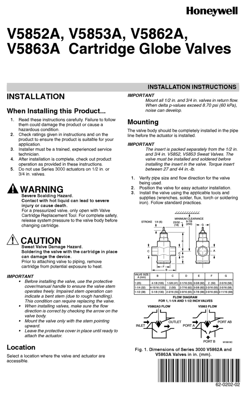
MOUNTING
The FCM-1 mounts directly to 4-inch square electrical boxes (see Figure 2A).
The box must have a minimum depth of 2
1
/
8
inches. Surface mounted electri-
cal boxes (SMB500) are available. The module can also mount to the DNR(W)
duct housing.
WIRING
NOTE: All wiring must conform to applicable local codes, ordinances, and reg-
ulations. When using control modules in nonpower limited applications, the
CB500 Module Barrier must be used to meet UL requirements for the separa-
tion of power-limited and nonpower-limited terminals and wiring. The barrier
must be inserted into a 4˝ × 4˝ × 2
1
/
8
˝ junction box, and the control module
must be placed into the barrier and attached to the junction box (Figure 2A).
The power-limited wiring must be placed into the isolated quadrant of the
module barrier (Figure 2B).
1. Install module wiring in accordance with the job drawings and appropri-
ate wiring diagrams.
2. Set the address on the module per job drawings.
3. Secure module to electrical box (supplied by installer), see Figure 2A.
Wire should be stripped to the appropriate length (recommended strip length
is
1
/
4
“ to
3
/
8
”). Exposed conductor should be secured under the clamping plate
and should not protrude beyond the terminal block area.
CAUTION: Do not loop wire under terminals. Break wire run to provide su-
pervision of connections.
SPECIFICATIONS
Normal Operating Voltage: 15 to 32 VDC
Maximum Current Draw: 6.5 mA (LED on)
Average Operating Current: 375μA (LED flashing - in group poll mode) 350μA (LED flashing - in direct poll mode); 485μA Max. (LED flashing, NAC shorted)
Maximum NAC Line Loss: 4 VDC
External Supply Voltage (between Terminals T10 and T11)
Maximum (NAC): Regulated 24 VDC
Maximum (Speakers): 70.7 V RMS, 50 W
Drain on External Supply: 1.7 mA Maximum using 24 VDC supply; 2.2 mA Maximum using 80 VRMS supply
Max NAC Current Ratings: For class B wiring system, the current rating is 3A; For class A wiring system, the current rating is 2A
Temperature Range: 32°F to 120°F (0°C to 49°C)
Humidity: 10% to 93% Non-condensing
Dimensions: 4
1
/
2
˝ H × 4˝ W × 1
1
/
4
˝ D (Mounts to a 4˝ square by 2
1
/
8
˝ deep box.)
Accessories: SMB500 Electrical Box; CB500 Barrier
I56-3500-003
INSTALLATION AND MAINTENANCE INSTRUCTIONS
IMPORTANT: When using the FCM-1 for fire fighter telephone applications,
remove Jumper (J1) and discard. The Jumper is located on the back as shown
in Figure 1B. The module does not provide ring back when used as a fire-
fighter telephone circuit.
J1 must be removed whenever power supply monitoring feature is not required.
FIGURE 1A: FIGURE 1B. JUMPER LOCATION:
J1
C1059-00 C0910-00
12 Clintonville Road
Northford, CT 06472-1653
Phone: 203.484.7161
C1070-00
FIGURE 2A. MODULE MOUNTING FIGURE 2B:
WITH BARRIER:
NO-460-004 3 I56-3500-003NO-460-004 2 I56-3500-003
FIGURE 5. TYPICAL WIRING FOR SPEAKER SUPERVISION AND SWITCHING, NFPA STYLE Y:
(+)
(–)
(+)
(–)
(+)
(–)
(–)
(+)
(–)
(+)
(+)
(–)
AUDIO CIRCUIT
DO NOT LOOP WIRE AROUND TERMINALS 10 & 11.
BREAK WIRE TO ENSURE
SUPERVISION OF CONNECTIONS.
SIGNAL LINE CIRCUIT (SLC)
32 VDC MAX.
TWISTED PAIR
IS RECOMMENDED
ALL WIRING SHOWN IS
SUPERVISED AND POWER LIMITED
WIRES MUST BE SUPERVISED PER NFPA
CONNECT MODULES TO LISTED COMPATIBLE
CONTROL PANELS ONLY
FROM
PANEL OR
PREVIOUS
DEVICE
CONTROL
MODULE
47K EOL
RESISTOR
ELR-47K
SPEAKERS MUST BE LISTED FOR FIRE PROTECTION.
REFER TO THE RELAY CONTACT RATING TABLE FOR
MAXIMUM LOAD.
TO NEXT
DEVICE
MODULE POLARITIES ARE
SHOWN IN ALARM
TO NEXT CONTROL MODULE
LAST MODULE MUST RETURN
WIRES FOR SUPERVISION
SUPERVISION
AUDIO CIRCUIT WIRING MUST BE TWISTED PAIR AS A MINIMUM.
SEE NOTIFIER INSTALLATION MANUAL FOR DETAILED INFORMATION.
AUDIO AMPLIFIER, 70.7 Vrms MAX.
USE ONLY MODELS AA-30, AA100 OR
AA-120. AMPLIFIER MUST PROVIDE
WIRING SUPERVISION PER NFPA.
*NOTE: ANY FAULT IN THE POWER SUPPLY IS LIMITED TO THAT ZONE AND DOES NOT RESULT IN A FAULT IN A SEPARATE ZONE.
C0949-00
FIGURE 6. TYPICAL FAULT TOLERANT WIRING FOR SPEAKER SUPERVISION AND SWITCHING, NFPA STYLE Z:
(+)
(–)
(+)
(–)
(+)
(–) (+)
(–)
(–)
(+)
(–)
(+)
ALL WIRING SHOWN IS SUPERVISED
AND POWER LIMITED
TO NEXT
DEVICE
SIGNAL LINE CIRCUIT (SLC)
32 VDC MAX.
TWISTED PAIR
IS RECOMMENDED
WIRES MUST BE SUPERVISED PER NFPA
CONNECT MODULES TO LISTED COMPATIBLE
CONTROL PANELS ONLY
FROM
PANEL OR
PREVIOUS
DEVICE
CONTROL
MODULE
SPEAKERS MUST BE LISTED FOR
FIRE PROTECTION. REFER TO THE
RELAY CONTACT RATING TABLE FOR
MAXIMUM LOAD.
47K EOL RESISTOR
IS INTERNAL AT
TERMINALS 8 & 9
MODULE POLARITIES ARE SHOWN IN ALARM
TO NEXT CONTROL
MODULE LAST MODULE
MUST RETURN WIRES FOR
SUPERVISION
SUPERVISION
AUDIO CIRCUIT WIRING MUST BE TWISTED PAIR AS A MINIMUM.
SEE NOTIFIER INSTALLATION MANUAL FOR DETAILED INFORMATION.
AUDIO AMPLIFIER, 70.7 Vrms MAX.
USE ONLY MODELS AA-30, AA100 OR
AA-120. AMPLIFIER MUST PROVIDE
WIRING SUPERVISION PER NFPA.
AUDIO CIRCUIT
DO NOT LOOP WIRE AROUND TERMINALS 10 & 11.
BREAK WIRE TO ENSURE
SUPERVISION OF CONNECTIONS.
BYPASS CAPACITORS: 100μ
A2143-20 NONPOLARIZED
<10μA LEAKAGE
*NOTE: ANY FAULT IN THE POWER SUPPLY IS LIMITED TO THAT ZONE AND DOES NOT RESULT IN A FAULT IN A SEPARATE ZONE.
C0950-00
WARNING
All relay switch contacts are shipped in the standby state (open) state, but may have transferred to the activated (closed) state during shipping. To ensure that
the switch contacts are in their correct state, modules must be made to communicate with the panel before connecting circuits controlled by the module.
FIGURE 3. TYPICAL NOTIFICATION APPLIANCE CIRCUIT CONFIGURATION, NFPA STYLE Y:
(+)
(+)
(+)
(+)
(+)
(+)
47K EOL
RESISTOR
ELR-47K
UL LISTED EOL
RELAY SHOWN
ENERGIZED
24 VDC COIL
EOLR-1
24 VDC CIRCUIT
DO NOT LOOP WIRE ON TERMINALS 10 & 11. BREAK WIRE
RUN TO PROVIDE SUPERVISION OF CONNECTIONS.
TO NEXT CONTROL MODULE OR
END-OF-LINE RELAY. ONE RELAY
REQUIRED FOR EACH CIRCUIT. SOME
CONTROL PANELS HAVE RELAY BUILT
IN AND DO NOT REQUIRE EXTERNAL
WIRING. REFER TO PANEL MANUAL.
24 VDC POWER SUPPLY
ISOLATED, REGULATED,
POWER LIMITED PER NFPA 70.
LISTED FOR FIRE PROTECTION
WITH BATTERY BACKUP.
MODULE POLARITIES ARE
SHOWN IN ALARM
CONNECT MODULES TO
LISTED COMPATIBLE CONTROL
PANELS ONLY
SIGNAL LINE CIRCUIT (SLC)
32 VDC MAX.
TWISTED PAIR
IS RECOMMENDED
ALL WIRING SHOWN IS SUPERVISED
AND POWER LIMITED
CONTROL
MODULE
FROM PANEL
OR PREVIOUS
DEVICE
TO NEXT
DEVICE
*NOTE: ANY FAULT IN THE POWER SUPPLY IS LIMITED TO THAT ZONE AND DOES NOT RESULT IN A FAULT IN A SEPARATE ZONE.
(–) (–)
(–) (–)
(–)
(–)
C0947-00
FIGURE 4. TYPICAL FAULT TOLERANT NOTIFICATION APPLIANCE CIRCUIT CONFIGURATION, NFPA STYLE Z:
(+)
(–)
(+)
(–)
(+)
(–)
(–)
(+)
(–)
(+)
(+)
(–)
ALL WIRING SHOWN IS SUPERVISED
AND POWER LIMITED
MODULE POLARITIES ARE
SHOWN IN ALARM
EOL RESISTOR
IS INTERNAL
AT TERMINALS
8 AND 9
UL LISTED EOL
RELAY SHOWN
ENERGIZED
24 VDC COIL
EOLR-1
TO NEXT CONTROL MODULE OR
END-OF-LINE RELAY. ONE RELAY
REQUIRED FOR EACH CIRCUIT. SOME
CONTROL PANELS HAVE RELAY BUILT
IN AND DO NOT REQUIRE EXTERNAL
WIRING. REFER TO PANEL MANUAL.
CONTROL
MODULE
TO NEXT
DEVICE
SIGNAL LINE CIRCUIT (SLC)
32 VDC MAX.
TWISTED PAIR
IS RECOMMENDED
CONNECT MODULES TO LISTED
COMPATIBLE CONTROL
PANELS ONLY
FROM PANEL
OR PREVIOUS
DEVICE
24 VDC CIRCUIT
DO NOT LOOP WIRE ON TERMINALS 10
& 11. BREAK WIRE RUN TO PROVIDE
SUPERVISION OF CONNECTIONS.
24 VDC POWER SUPPLY
ISOLATED, REGULATED,
POWER LIMITED PER
NFPA 70. LISTED FOR
FIRE PROTECTION WITH
BATTERY BACKUP.
*NOTE: ANY FAULT IN THE POWER SUPPLY IS LIMITED TO THAT ZONE AND DOES NOT RESULT IN A FAULT IN A SEPARATE ZONE.
C0948-00

Other Honeywell Control Unit manuals

Honeywell Galaxy 2 Series User manual

Honeywell

Honeywell Galaxy 2 Series User manual

Honeywell S8910U Original instructions

Honeywell

Honeywell S8910U Original instructions

Honeywell PWT-BV Operation manual

Honeywell

Honeywell PWT-BV Operation manual

Honeywell FF-SRE6029 User manual

Honeywell

Honeywell FF-SRE6029 User manual

Honeywell SUPER TRADELINE S8610U User manual

Honeywell

Honeywell SUPER TRADELINE S8610U User manual

Honeywell VR4920Z 1000 User manual

Honeywell

Honeywell VR4920Z 1000 User manual

Honeywell Satronic DMG 973 User manual

Honeywell

Honeywell Satronic DMG 973 User manual

Honeywell N-1000 Service manual

Honeywell

Honeywell N-1000 Service manual

Honeywell SG150 User manual

Honeywell

Honeywell SG150 User manual

Honeywell SG160S User manual

Honeywell

Honeywell SG160S User manual

Honeywell RM7823A User manual

Honeywell

Honeywell RM7823A User manual

Honeywell ADEMCO 4204 User manual

Honeywell

Honeywell ADEMCO 4204 User manual

Honeywell V4730B User manual

Honeywell

Honeywell V4730B User manual

Honeywell TR120 User manual

Honeywell

Honeywell TR120 User manual

Honeywell BRAUKMANN SG 162 User manual

Honeywell

Honeywell BRAUKMANN SG 162 User manual

Honeywell Silent Knight SK-Relay-6 User manual

Honeywell

Honeywell Silent Knight SK-Relay-6 User manual

Honeywell V-Plex ADEMCO 4297 Assembly instructions

Honeywell

Honeywell V-Plex ADEMCO 4297 Assembly instructions

Honeywell VSxF-2 User manual

Honeywell

Honeywell VSxF-2 User manual

Honeywell Krom Schroeder VAN Series User manual

Honeywell

Honeywell Krom Schroeder VAN Series User manual

Honeywell RV281 User manual

Honeywell

Honeywell RV281 User manual

Honeywell SmartValve SV9520H User manual

Honeywell

Honeywell SmartValve SV9520H User manual

Honeywell VS8521 User manual

Honeywell

Honeywell VS8521 User manual

Honeywell D15P User manual

Honeywell

Honeywell D15P User manual

Honeywell RV284 User manual

Honeywell

Honeywell RV284 User manual

Popular Control Unit manuals by other brands

Leadshine EM422S user manual

Leadshine

Leadshine EM422S user manual

Cutler-Hammer ATC-400 instructions

Cutler-Hammer

Cutler-Hammer ATC-400 instructions

Hi-Link HLK-RM08S user manual

Hi-Link

Hi-Link HLK-RM08S user manual

Pentek 4200A operating manual

Pentek

Pentek 4200A operating manual

Emerson CSI 6500 quick start guide

Emerson

Emerson CSI 6500 quick start guide

Emerson Keystone PED Operating and safety instructions

Emerson

Emerson Keystone PED Operating and safety instructions

Bosch Rexroth NYCe 4000 instructions

Bosch

Bosch Rexroth NYCe 4000 instructions

Fortinet FIM-7920E Guide

Fortinet

Fortinet FIM-7920E Guide

SMC Networks VFR4000 Series Operation manual

SMC Networks

SMC Networks VFR4000 Series Operation manual

Elnec DIL32/MLF32-1 ZIF-CS manual

Elnec

Elnec DIL32/MLF32-1 ZIF-CS manual

EKE-Electronics EKE-Trainnet MVB2791B Technical manual

EKE-Electronics

EKE-Electronics EKE-Trainnet MVB2791B Technical manual

H3C Campus SeerEngine LSXM1SEERBXC2 quick start guide

H3C

H3C Campus SeerEngine LSXM1SEERBXC2 quick start guide

ERHARD NON SLAM operating instructions

ERHARD

ERHARD NON SLAM operating instructions

Zimmer ZR1000-A Series Installation and operating instructions

Zimmer

Zimmer ZR1000-A Series Installation and operating instructions

ABB Relion 670 series Commissioning manual

ABB

ABB Relion 670 series Commissioning manual

bonitron M3699 Reference manual

bonitron

bonitron M3699 Reference manual

RBH Access Technologies AxiomV manual

RBH Access Technologies

RBH Access Technologies AxiomV manual

Hitachi HX-RIO3 Series user manual

Hitachi

Hitachi HX-RIO3 Series user manual

manuals.online logo
manuals.online logoBrands
  • About & Mission
  • Contact us
  • Privacy Policy
  • Terms and Conditions

Copyright 2025 Manuals.Online. All Rights Reserved.