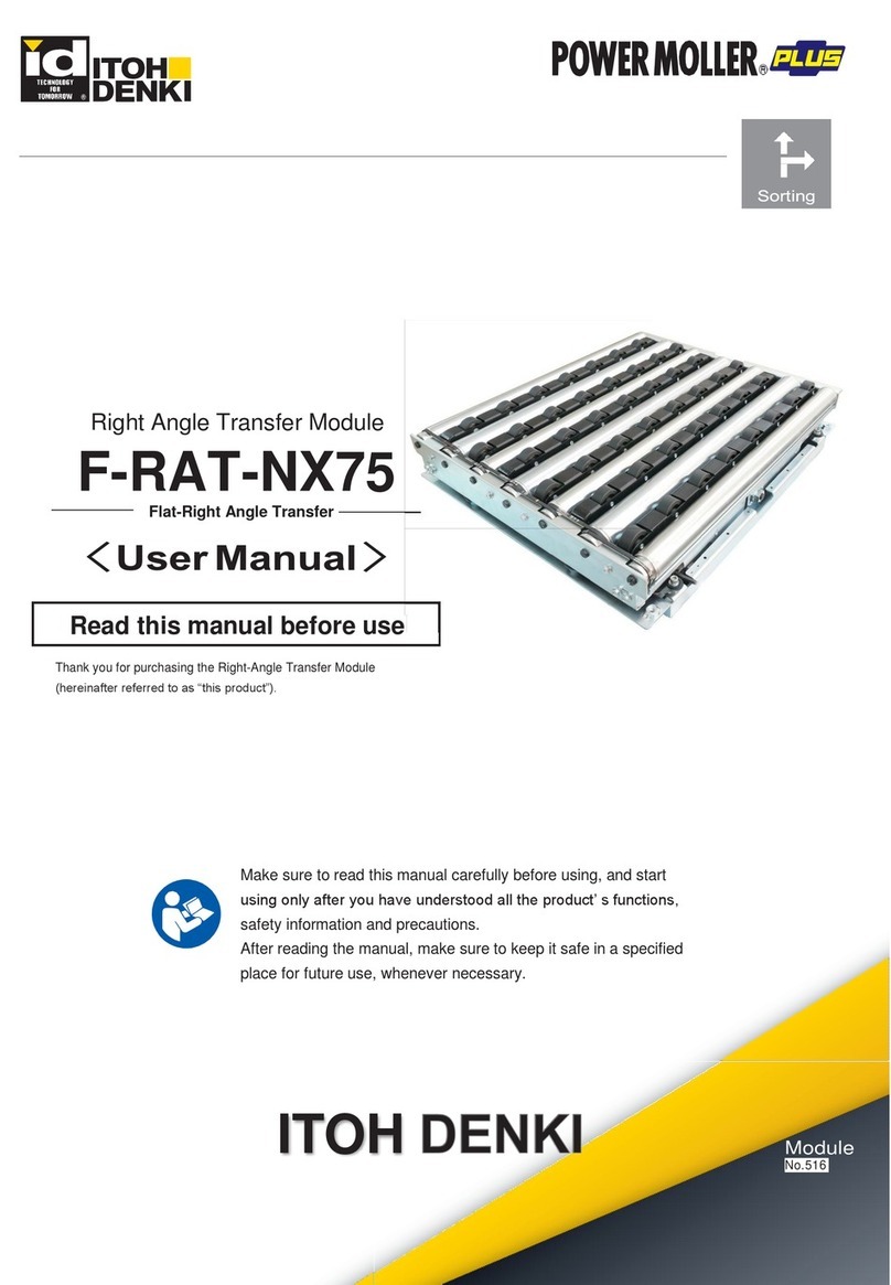
ITOH DENKI F-RAT-NX75 User manual

F-RAT-NX75
Flat-Right Angle Transfer
Right Angle Transfer Module
〈 Annex User Manual 〉
Make sure to read this manual carefully before using, and start
using only after you have understood all the product’ s functions,
safety information and precautions.
After reading the manual, make sure to keep it safe in a specified
place for future use, whenever necessary.
A PC application “itoh Configurator for EtherNet IP and PROFINET (hereinafter referred to as “ICEP”)” and its
user manual are necessary for IB-P02F-P-FT setting and programming.
Contact us for the application and user manual.
Module
ITOH DENKIITOH DENKI
Sorting
Thank you for purchasing the Right Angle Transfer Module
(hereinafter referred to as “this product”).
Read this manual before use
Original notice - U1.1
This manual is designed for PNP version of control boards.
Please contact your local supplier for details.
For IB-P02F-P-FT

2F-RAT-NX75AnnexUserManualforIB-P02F-P-FT
1. INDEX
INDEX
1.
2.
3.
4.
5.
6.
7.
Appendix
INDEX
Advanced preparation
Product check
Wiring
IB-P02F-P-FT settings
6-1. Setting preparation
6-2. Property settings
Control/Operation
6-1. Creating the ladder logic
6-1-1. Switching the transfer direction
6-1-2. Changing the speed
6-2. Basic operation
6-2-1. Switching the transfer surface
6-2-2.
About the initial position setting (teaching) of the transfer surface
6-3. Program example
6-4. What to do before operation
Maintenance/Inspection
7-1. LED indication
7-2. Checking and releasing errors
Appendix 1. Product specifications
…… 2
…… 3
…… 9
…… 11
…… 19
…… 21
…… 24
…… 28
…… 30
…… 34
…… 34
…… 35
…… 40
…… 41
…… 42
…… 43
…… 45
…… 46
…… 50
…… 52
…… 53
INDEX
Advanced preparationProduct checkWiringControl/OperationMaintenance/InspectionAppendix IB-P02F-P-FT settings
Original notice - U1.1

3F-RAT-NX75AnnexUserManualforIB-P02F-P-FT
2.Advanced preparation
Advanced preparationProduct checkWiringControl/OperationMaintenance/InspectionAppendix IB-P02F-P-FT settings
Original notice - U1.1

4
HBM-201
AC power
source
AC power
source
0
1
2.Advanced preparation
Before introducing this product, prepare the following devices separately.
As for the sensor input, and input/output signals of driver cards,
adopt the number of inputs/outputs based on operation.
F-RATmainunit
24V DC motor power unit
Emergency
stop switch
Sensors
Breaker
【Important】
Wiring image
Items to be prepared
by customers
Install the emergency stop equipment on the side of the DC motor power supply unit to
which the power is supplied.
This product does not include the emergency stop equipment.
Customers must make sure to install it.
Emergency stop
equipment
Regarding facilities where this product is incorporated, check that a breaker with
appropriate capacity for the 24V DC power supply unit has been installed. If abnormal
operation should occur, protection through the breaker could be effective.
Note that when using an earth leakage breaker, select one that is “inverter
corresponding”. (Some inverter non-corresponding earth leakage breakers
can be triggered, since they may recognize high-frequency components of the switching
power supply as leakage.)
When the 24V DC power supply unit has been incorporated, check that the breaker
and emergency stop switch can work properly. Perform operation following the trial
operation after checking them.
① Input to the DC power supply is securely turned ON/OFF when turning ON/OFF the
breaker.
② Input to this product (24V DC) is securely turned ON/OFF when turning ON/OFF
the emergency stop switch.
Checking the breaker
Operation check
Emergency stop switch
To this product Emergency stop equipment
Breaker
Emergency stop equipment
24V DC
motor
power supply
F-RAT-NX75AnnexUserManualforIB-P02F-P-FT
Advanced preparationProduct checkWiringControl/OperationMaintenance/InspectionAppendix IB-P02F-P-FT settings
Original notice - U1.1
IB-P02F-P-FT
IB
-P02F-P-
FT
IB
24V DC control power unit
5
When overcurrent protection devices need to be installed to the DC power supply, some
power supplies that need to conform to the safety standards (UL60950-1, etc.) require
installation of the specified overcurrent protection device based on their specifications. In
such cases, make sure to install the specified overcurrent protection device as described in
the figure below. When overcurrent protection devices are not required in the DC power
supply specifications, they do not need to be installed.
Aboutthewiringmethod
Aboutthe
wiringmethod ■When overcurrent protection devices are required
In the event that a failure occurs, such as overload or abnormal temperature, IB-P02F-P-FT
will transmit the data of failure generation to external devices via the PROFINET
communications, as well as stopping the drive operation. However, it does not have the
MDR power shutdown function. Accordingly, if the MDR power needs to be shut down in the
event of a failure, as described in SW1 of the figure below, add the power shutdown circuit
using a PC, and shut down the power from these devices in the event of a failure.
When the communication function on the controller is not used, a failure cannot be detected
from the communication data. For this reason, to shut down the MDR power, independent
overload detection devices that have the power shutdown function need to be added outside
this product.
■Adding the MDR* power shutdown circuit in the event of a failure
Motor
power
supply
DC power supply
DC power supply unit
SW1
shutdown contact
PROFINET
PROFINET communications
PC or PLC for control
IB-P02F-P-FT
IB-P02F-P-FT
Factory
AC power
Emergency
stop switch
Breaker
F-RAT-NX75AnnexUserManualforIB-P02F-P-FT
2.Advanced preparation
Advanced preparationProduct checkWiringControl/OperationMaintenance/InspectionAppendix IB-P02F-P-FT settings
Original notice - U1.1
Overcurrent
protection
Factory
AC power
Overcurrent
protection
SW1
24V
0V Motor
DC power supply
Overcurrent
protection
Overcurrent
protection
24V
0V Control
Emergency
stop switch
*MDR = motorized roller

6F-RAT-NX75AnnexUserManualforIB-P02F-P-FT
2.Advanced preparation
Power supply equipment to supply 24V DC to this product
24V DC power supply
Zone sensors to check the tray, and area sensors to check loading and discharging, etc.
Sensors
Switching power supply (24V DC/10A, 240W or more)
24V DC Battery
Zone sensor
Term
A sensor to detect the existence of trays within the zone
Area sensor
A sensor to detect load and discharge of trays
Area sensor (Load)
Area sensor (Discharge)
F-RAT zone sensor
Area sensor (Discharge)
24VDCpowersupply
■A switching power supply is recommended as the DC power supply (24V
DC±10%) for drivers.
■Use a stabilized power supply that has an adequate capacity of 24V DC and
10A or higher and does not fluctuate due to load variation.
■If the capacity of the power supply is less than the rated power of this product,
it may cause the supply voltage leading malfunction or damage.
Be sure to use the power supply with a capacity larger than the rated power of
this product.
■For the power supply unit, use an isolation type switching power supply
compliant with the safety standard (IEC60950-1 or UL60950-1) for Information
technology equipment.
■The power supply shall have a capacity larger than the rated value of this
product.
■A transformer type power supply cannot be used.
■Secure a voltage of 24V DC±10% at the power supply terminal of a driver card.
■In addition, the power supply should not activate protection with peak current
30A for 1ms or below.
■
Operation
Since F-RAT uses MDR for each of carrier wheel transfer, roller transfer,
and drive switching (3 MDRs in total), it is not recommeded to use multiple
MDRs at the same time.
Transfer direction
Advanced preparationProduct checkWiringControl/OperationMaintenance/InspectionAppendix IB-P02F-P-FT settings
Original notice - U1.1

7
PC
Application
PROFINET cable
PC・Application
■Use ICEP Ver 2.1.5.0 or later.
■Illustrations and/or procedures shown below may partly differ depending on your PC.
In such cases, perform settings and operations to ensure the application will be
safely installed of your own accord, and under your own responsibility.
PCs that meet the following requirements
Category 5e or more
・OS: Microsoft Windows 7 or later
・CPU: CPU core i5 or higher
・Memory: 4 GByte or more
・Framework Ver 4.5 or higher
・CRT resolution: 1024×768 [XGA]
・PCs in which data area has to be secured sufficiently
・Keyboard/Mouse (Touch operation unavailable)
※If Framework has not been installed, install Framework Ver.4.5.
※If some problems resulting from other factors have been found,
it is possible we cannot address them in the specifications,
depending on the contents. We appreciate your understanding.
Installingthedesignatedapplication
A PC application “ICEP” and its user manual are necessary for IB-P02F-P-FT setting and
programming.
Contact us for the application and «ICEP» user manual.
Start the ICEP setup
program.
Proceed to the
installation according
to the instructions on
the screen.
Click to start
installation
1
2
3
4
Acceptthelicenseagreementarticles,
andclick
※Whenthefollowingscreenisdisplayed
duringinstallation,click“Yes”.
When installation is
complete, the ICEP
icon will be displayed
on the PC’ s desktop.
Click
Click
Click
F-RAT-NX75AnnexUserManualforIB-P02F-P-FT
2.Advanced preparation
Advanced preparationProduct checkWiringControl/OperationMaintenance/InspectionAppendix IB-P02F-P-FT settings
Original notice - U1.1

8
MDR extension cable
(option)
Wiring materials Necessary for wiring power and signal cables to driver cards.
60
L
±5
37
(Male side)
(Female side)
Model
10P extension cable length
ACE-CBM-A0600
ACE-CBM-A1200
L= 600mm
L=1200mm
Model
12P extension cable length
ACE-CBM-G0600
ACE-CBM-G1200
L= 600mm
L=1200mm
Necessary when the installing location of the F-RAT main unit is far from that of the
driver cards.
■12P extension cable:F-RAT〔M1 / M2〕―IB-P02F-P-FT
〔MA〕
■10P extension cable:F-RAT〔M3〕―HBM-201
〈Available wire diameter for driver card connectors〉
60
L
±5
(Male side)
(Female side)
37
37.5
32.5
MDRextensioncable(option)
■Use extension cables of 1200 mm or less.
■Securely insert each connector part.
■To select the current capacity of wiring materials, secure a high safety margin
based on the current value in the equipment to be used.
■Longer wiring between the power supply unit and driver cards/controllers could
cause the voltage to decrease, resulting in malfunction and/or damage.
F-RAT-NX75AnnexUserManualforIB-P02F-P-FT
2.Advanced preparation
Motor power connector
Driver card
Connector IB-P02F-P-FT
0.5〜1.5m㎡(AWG:20〜14)
0.08〜0.5m㎡(AWG:28〜20)
1.25〜2.5m㎡(AWG:16〜12)
Advanced preparationProduct checkWiringControl/OperationMaintenance/InspectionAppendix IB-P02F-P-FT settings
Original notice - U1.1
300
Model
10P/12P conversion cable length
ACT-IBE-C0300 L= 300mm
10P/12P conversion cable x1
HBM-201
Control connector
Power
connector Control power connector
0.08〜1.5m㎡(AWG:28〜14)

9F-RAT-NX75AnnexUserManualforIB-P02F-P-FT
3.Productcheck
Product check
Advanced preparationProduct checkWiringControl/OperationMaintenance/InspectionAppendix IB-P02F-P-FT settings
Original notice - U1.1

10 F-RAT-NX75AnnexUserManualforIB-P02F-P-FT
Depending on the F-RAT input and output signal type, driver cards with the NPN (N) or PNP (P)
signal input are included. (Not included when not driver card has been specified.)
Check that all the following items are included.
Hex. bolt with spring lock and plain washers M8 x 20
Driver card・
Conversion cable
For F
−
RAT
−
N60X
−
□□□
−
□□□□
×4
Driver card HBM-201BP ×1
Cross-recessed head SW screw
M4×15
Cross-recessed
pan head screw
M4×10
Hex. nut
M4
Hex. nut
M4
Spring washer
M4
Driver card IB-P02F-P-FT ×1
Motor power connector
WAGO231-302/026-000
Power connector
WAGO734-102
I/O connector
WAGO733-110
Sensor connector
WAGO733-104
Control connector
〈ForHBM-201〉
〈For carrier wheel / roller transfer 〉
〈For drive switching 〉
×1
×1 ×1
×1
×2
×2
×4 ×4
×2 ×2
10P/12P conversion cable ×1
ACT-IBE-C0300
300
3.Product check
Checking accessories
For installing the
F-RAT main unit
Checking accessories
Advanced preparationProduct checkWiringControl/OperationMaintenance/InspectionAppendix IB-P02F-P-FT settings
Original notice - U1.1
POWER
BF
SF
LAN 2
SEN A
ACT 1
LAN 1
MOT A
STS A
IN 2
IN 3
IN 4
OUT 2
OUT 3
OUT 4
ACT 2
LAN 2
MOT B
STS B
SEN B
MA-SYN
MB-SYN
Motor Power
0V
24V
FG
0V
24V
Control
Power
Sensor A
0V
ALM
SEN
24V
0V
OUT1
OUT3
OUT2
Sensor B
IN/OUT
24V
SEN
ALM
0V
24V
IN1
IN2
IN3
IN4
OUT4
OUT 1
IN 1
IB-P02F-P-FT
MOTOR B
LAN 1
MOTOR A
MAC:00-22-21-XX-XX-XX
IB-P02F
NXP:030C, R8C:8103
2
1
34
R494
R469
LED407
LED416
LED401
LED409
RG300
LED406
R495
LED404
LED405LED420
LED421
LED402
LED403
LED419
SW1
2
1
34
R475
R476
LED408
LED417
LED400
R464
LED412
LED413
LED415
LED410
LED411
R494
R469
LED407
LED416
LED418
LED401
LED409
RG300
LED406
R495
LED404
LED405LED420
LED421
LED402
LED403
LED419
SW1
2
1
34
R475
R476
LED408
LED417
LED400
R464
LED412
LED413
LED415
LED410
LED411
R494
R469
LED407
LED416
LED41
LED401
LED409
RG300
LED406
R495
LED404
LED405LED420
LED421
LED402
LED403
LED419
SW1
2
1
34
R475
R476
LED408
LED417
LED400
R464
LED412
LED413
LED415
LED410
LED411
Control power connector
WAGO734-103
×1
WAGO733-105

11 F-RAT-NX75AnnexUserManualforIB-P02F-P-FT
L
4.Wiring
Wiring
Advanced preparationProduct checkWiringControl/OperationMaintenance/InspectionAppendix IB-P02F-P-FT settings
Original notice - U1.1

12 F-RAT-NX75AnnexUserManualforIB-P02F-P-FT
4.Wiring
IB-P02F-P-FT
HBM-201
50
26.6
169
40
161
4- 4.5
■Use extension cables of 1200 mm or less.
■Do not extend cables by connecting multiple extension cables.
Determine the mounting location for zone sensors, and area sensors for loading and
discharging, and prepare for them to be mounted.
Mounting preparation
for driver cards
Mountingpreparation
forsensors
If the mounting location of the F-RAT main unit is far from that of driver cards, prepare
the MDR extension cables separately.
Preparation of MDR
extension cables
●12P extension cable:F-RAT〔M1/M2〕―IB-P02F-P-FT
〔MA〕・・・ACE-CBM-G
●10P extension cable:F-RAT〔M3〕―HBM-201・・・・・・・・・ACE-CBM-A
Area sensor (Load)
Area sensor (Discharge)
Zone sensor
Area sensor (Discharge)
Example)
Mounting positions
for each sensor
Mounting preparation for driver cards
Holeprocessingonframesandcontrolpanel
・Perform mounting processing on the frames and control panel by reference
to the mounting holes for driver cards.
・For cable opening and projection from the F-RAT main unit, refer to
Mounting preparation for the F-RAT main unit (Technical document
FRAT-NX75 - P.24).
1
■Mount driver cards on a flat surface where heat can be released easily.
■Prevent chips generated during processing from entering driver cards.
Transfer direction
Advanced preparationProduct checkWiringControl/OperationMaintenance/InspectionAppendix IB-P02F-P-FT settings
Original notice - U1.1
160 fixing hole centres
2 x 4.2mm Ø hole
38,8
84,3
137 30,5
170
POWER
BF
SF
LAN 2
SEN A
ACT 1
LAN 1
MOT A
STS A
IN 2
IN 3
IN 4
OUT 2
OUT 3
OUT 4
ACT 2
LAN 2
MOT B
STS B
SEN B
MA-SYN
MB-SYN
Motor Power
0V
24V
FG
0V
24V
Control
Power
Sensor A
0V
ALM
SEN
24V
0V
OUT1
OUT3
OUT2
Sensor B
IN/OUT
24V
SEN
ALM
0V
24V
IN1
IN2
IN3
IN4
OUT4
OUT 1
IN 1
IB-P02F-P-FT
MOTOR B
LAN 1
MOTOR A
MAC:00-22-21-XX-XX-XX
IB-P02F
NXP:030C, R8C:8103
2
1
34
R494
R469
LED407
LED416
LED401
LED409
RG300
LED406
R495
LED404
LED405LED420
LED421
LED402
LED403
LED419
SW1
2
1
34
R475
R476
LED408
LED417
LED400
R464
LED412
LED413
LED415
LED410
LED411
R494
R469
LED407
LED416
LED418
LED401
LED409
RG300
LED406
R495
LED404
LED405LED420
LED421
LED402
LED403
LED419
SW1
2
1
34
R475
R476
LED408
LED417
LED400
R464
LED412
LED413
LED415
LED410
LED411
R494
R469
LED407
LED416
LED41
LED401
LED409
RG300
LED406
R495
LED404
LED405LED420
LED421
LED402
LED403
LED419
SW1
2
1
34
R475
R476
LED408
LED417
LED400
R464
LED412
LED413
LED415
LED410
LED411

13
4.Wiring
F-RAT-NX75AnnexUserManualforIB-P02F-P-FT
HBM-201
M1
M1
M3
M3
M2
M2
Roller MDR Drive switching MDR Carrier wheel MDR
For roller MDR
For carrier wheel MDR
For drive switching MDR
IB-P02F-P-FT
MA MB
Conversion cable
・ IB-P02F-P-FT
: 0.74N・m
・ HBM-201: 1.0N・m
Mount customer-prepared zone sensor and area sensor for loading and discharging,
as well as power supply units, and PLCs.
・Refer to the labels for cables coming from the F-RAT main unit, and securely
connect the MDR connectors and driver cards.
・When using extension cables, securely connect them to the MDR connectors, as
well as to the driver card connectors.
Use the included screws and nuts to mount driver
cards on the conveyor frames or control panel.
Mounting driver cards
Connection between the
F-RAT main unit and
driver cards
Mounting sensors,
control devices, and
power supply units
Wiring
Mountingdrivercards
Mountingsensors,controldevices,andpowersupplyunits
ConnectionbetweentheF-RATmainunitanddrivercards
■Recommended tightening torque
Advanced preparationProduct checkWiringControl/OperationMaintenance/InspectionAppendix IB-P02F-P-FT settings
Original notice - U1.1

14
4.Wiring
F-RAT-NX75AnnexUserManualforIB-P02F-P-FT
Wiring example (image)
:F-RATzonesensor
:Areasensor(ontheoppositesideofV-ribbedpulley)
:Areasensor(onthesideofV-ribbedpulley)
:Areasensor(ontheleftsidewhenviewingV-ribbedpulleyfromthefront)
:Areasensor(ontherightsidewhenviewingV-ribbedpulleyfromthefront)
SA
SA
②①
①
②
③
④
④
③
F-RAT
V-ribbed pulley
Advanced preparationProduct checkWiringControl/OperationMaintenance/InspectionAppendix IB-P02F-P-FT settings
Original notice - U1.1
#1 0V
#2 24V
#3 IN1
#4 IN2
#5 IN3
#6 IN4
#7 OUT4
#8 OUT3
#9 OUT2
#10 OUT1
ALM #4 #1 24V
0V #3 #2 SEN
SEN #2 #3 0V
24V #1 #4 ALM
#1 #2 #3 #4 #5
HBM-201
)ArotoM(101NC
CN201 (Motor B)
IB-P
Series
Roller transfer
MDR
㸦㹋2㸧
Drive switching MDR
㸦㹋3㸧
24V DC
IB-P
Series
24V DC Motor Power
IN1 IN2 CN1
CN2
F-RAT zone sensor
IB-P02F-P-FT
OUT1 OUT2 N/A
24V DC Control Power
Carrier wheel transfer MDR
㸦㹋1㸧CN304 CN305
Area Sensor ༃
Area Sensor ༄
Area Sensor ༅
Area Sensor ༆
CN301
LAN1
LAN2
CN1
CN302
(Remote IN/OUT)

15
4.Wiring
F-RAT-NX75AnnexUserManualforIB-P02F-P-FT
CN1/CN301 :
Motor power connector
Control power connector
CN302 〜CN305:
Remote input/
Remote output/
Sensor connector
1.25〜2.5mm2(AWG:16〜12)
Connect the 24V DC and 0V cables to CN1
(2 pin) / CN301 (3pin).
Connect customer-prepared sensor input/output
cables to each connector.
※Refer to the wiring example image (P.14), and
perform wiring according to operation.
〔IB-P02F-P-FT〕
8〜9mm
24V DC
(
AWG:28
〜
20
)
0V
7mm 0.08〜0.5mm2
MotorPower
connector(CN1)
Control connector
(CN302 〜CN305)
IB-P02F-P-FTwiring
IB-P02F-P-FTwiring
1
2
Connect the motor power connector (CN1),
control power connector (CN301) and control
connector (CN302 - CN305) to driver cards.
Connecting to driver cards 3
■Do not connect multiple power cables to one
pole. Failure to follow this could result in
electric shock, short circuit, and/or damage
due to the capacity of connectors being
exceeded.
■Do not connect the 24V DC and 0V cables
incorrectly.
■Do not connect cables when connectors are
plugged in.
#1 0V
#1 #4
#1 #3
#1 #10
#2 24V DC
#1 24V
#2 Sensor input
#3 0V
#4 Optional sensor alarm input
#1 24V
#2 0V
#3 FG
#1 0V
#2 24V
#3 INPUT1
#4 INPUT2
#5 INPUT3
CN1:Power connector
CN304/CN305:Sensor connectors
CN301:Control supply
CN302:Inputs / outputs connector
Advanced preparationProduct checkWiringControl/OperationMaintenance/InspectionAppendix IB-P02F-P-FT settings
Original notice - U1.1
POWER
BF
SF
LAN 2
SEN A
ACT 1
LAN 1
MOT A
STS A
IN 2
IN 3
IN 4
OUT 2
OUT 3
OUT 4
ACT 2
LAN 2
MOT B
STS B
SEN B
MA-SYN
MB-SYN
Motor Power
0V
24V
FG
0V
24V
Control
Power
Sensor A
0V
ALM
SEN
24V
0V
OUT1
OUT3
OUT2
Sensor B
IN/OUT
24V
SEN
ALM
0V
24V
IN1
IN2
IN3
IN4
OUT4
OUT 1
IN 1
IB-P02F-P-FT
MOTOR B
LAN 1
MOTOR A
MAC:00-22-21-XX-XX-XX
CN201
CN101
IB-P02F
NXP:030C, R8C:8103
2
1
34
R494
R469
LED407
LED416
LED401
LED409
RG300
LED406
R495
LED404
LED405LED420
LED421
LED402
LED403
LED419
SW1
2
1
34
R475
R476
LED408
LED417
LED400 R464
LED412
LED413
LED415
LED410
LED411
R494
R469
LED407
LED416
LED418
LED401
LED409
RG300
LED406
R495
LED404
LED405LED420
LED421
LED402
LED403
LED419
SW1
2
1
34
R475
R476
LED408
LED417
LED400 R464
LED412
LED413
LED415
LED410
LED411
R494
R469
LED407
LED416
LED41
LED401
LED409
RG300
LED406
R495
LED404
LED405LED420
LED421
LED402
LED403
LED419
SW1
2
1
34
R475
R476
LED408
LED417
LED400 R464
LED412
LED413
LED415
LED410
LED411
4
1
10
1
1
4
1
3
CN302
CN402
CN305
CN401
CN304
CN301
CN1
SW1
#6 INPUT4
#7 OUTPUT4
#8 OUTPUT3
#9 OUTPUT2
#10 OUTPUT1
CN101/CN201 : Motor connectors
#1 #12
#1 GND (Gray)
#2 +12V (Blue)
#3 Motor coil U (Red)
#4 Motor coil U (Pink)
#5 Motor coil V (White)
#7 Motor coil W (Black)
#8 Motor coil W (Brown)
#9 Hall signal (Purple)
#10 Hall signal (Orange)
#11 Hall signal (Green)
#6 Motor coil V (Yellow)
#12 Motor thermal (light blue)
For the motor output setting
CN401/CN402 : RJ45 connectors
#8 #1
#1 Tx+ (transmission data +)
#2 Tx- (transmission data -)
#3 Rx+ (reception data +)
#4 Not used
#5 Not used
#7 Not used
#8 Not used
#6 Rx- (reception data -)
(
AWG:28
〜
14
)
7mm 0.08〜1.5mm2
Control power connector
CN301

16 F-RAT-NX75AnnexUserManualforIB-P02F-P-FT
4.Wiring
Input/output circuit
CN302
IB-P02F-P-FTwiring
■Set the voltage used for remote input within the range of 18V DC to 30V DC.
[Remote input/output (CN302)] 733-110 (WAGO)
• Remote Input : 25mA max
• Remote output : 100mA max
・Inputs & outputs are PNP only
Remote input interface circuit diagram
Advanced preparationProduct checkWiringControl/OperationMaintenance/InspectionAppendix IB-P02F-P-FT settings
Original notice - U1.1
#1 #10
#1 0V
#2 24V
#3 INPUT1
#4 INPUT2
#5 INPUT3
CN302:Inputs / outputs connector
#6 INPUT4
#7 OUTPUT4
#8 OUTPUT3
#9 OUTPUT2
#10 OUTPUT1
Remote output interface circuit diagram

17
#1 #2 #3 #4 #5
#1 24V DC
#2 0V
F-RAT-NX75AnnexUserManualforIB-P02F-P-FT
4.Wiring
( )
( )
CN1
(Power)
#2
#1
0V
24V DC CN2
CN1
IN HBM-201BN:0V
HBM-201BP:24V
}
OUT
}
HBM-201BN:0V
HBM-201BP:24V
・Carrier wheel and roller transfer surface are switched by inputting
signal
・Teaching settings can be performed when both #4 and #5 are ON
・Teaching has not completed when both #1 and #2 are ON
(when the power is turned on)
・Transfer surfaces are being switched, and teaching is in operation
when both #1 and #2 are OFF
・Open collector output
Functions Detailed descriptions
CN2
(Control)
#5
#4
#3
#2
#1
Input
Input
−
Output
Output
24V
0V
24V
0V
N/A
N/A
INPUT1
INPUT2
OUT 1
OUT 2
21
12345
0V
24V DC
■Connector descriptions
Carrier wheel surface
switch input
Roller surface
switch input
Unused
Carrier wheel surface
standby output
Roller surface
standby output
7mm
24V DC
(
AWG:28
〜
20
)
0V
7mm 0.08〜0.5mm2
0.50〜1.5mm2(AWG:20〜14)
Teaching
Term
Operation to perform the initial setting of the transfer surface position.
Teaching must be performed after the power is turned on.
〔HBM-201〕
M3:Drive switching
HBM-201
Wiring for HBM-201
WiringforHBM-201
Power connector (CN1) Connect the 24V DC and 0V cables to CN1
(2 pin).
1
■Do not connect multiple power cables to one
pole. Failure to follow this could result in
electric shock, short circuit, and/or damage
due to the capacity of connectors being
exceeded. (Connector capacity: 10A)
■Do not connect the 24V DC and 0V cables
incorrectly.
■Do not connect cables when connectors are
plugged in.
Control connector (CN2) Connect the above four cables.
2
■Use the same voltage to be input to CN2#1 as
the power supply voltage.
(Connector capacity: 4A)
Powerconnector
(CN1)
Controlconnector
(CN2)
Connect the power connector (CN1), and control
connector (CN2) to driver cards.
Connecting to driver cards 3
*
*
*
Advanced preparationProduct checkWiringControl/OperationMaintenance/InspectionAppendix IB-P02F-P-FT settings
Original notice - U1.1

18
■Do not change the factory settings.
Switch settings Turn the driver card DIP switch and rotary switch to the following
(factory setting).
4
SW1
SW1
#1 #2 #3 #4 #5 #6 #7 #8
OFF OFF OFF OFF OFF OFF OFF OFF
SW2 SW3
3WS2WS
#1 #2 #3 #4 #5 #6 #7 #8
ON OFF ON ON OFF OFF OFF
5
6
7
8
9
0
1
2
3
4
ON
HBM-201BP HBM-201BN
OFF
HBM−201B
F-RAT-NX75AnnexUserManualforIB-P02F-P-FT
4.Wiring
Wiring for HBM-201
Advanced preparationProduct checkWiringControl/OperationMaintenance/InspectionAppendix IB-P02F-P-FT settings
Original notice - U1.1

19
5.IB-P02F-P-FTsettings
F-RAT-NX75AnnexUserManualforIB-P02F-P-FT
5-1. Setting preparation
5-2. Property settings
……21
……24
Advanced preparationProduct checkWiringControl/OperationMaintenance/InspectionAppendix IB-P02F-P-FT settings
Original notice - U1.1

}
}
}
20
Flow of settings
5.IB-P02F-P-FTsettings
IB-P02F-P-FT controls the F-RAT with the property settings and ladder logic.
This section explains the setting preparation and property settings.
Flowofsettings
5-1.
Setting preparation
Setting the IP address
↓
Creating the project file
↓
Registering IB-P02F-P-FT to be used
↓
IB-P02F-P-FT property settings
↓
Writing properties
Complete
↓
Creating the IB-P02F-P-FT ladder logic
↓
Writing the ladder logic
↓
F-RAT-NX75AnnexUserManualforIB-P02F-P-FT
5-2.
Property settings
6-1.
Creating the ladder logic
Advanced preparationProduct checkWiringControl/OperationMaintenance/InspectionAppendix IB-P02F-P-FT settings
Original notice - U1.1
Other manuals for F-RAT-NX75
2
Table of contents
Other ITOH DENKI Control Unit manuals
Popular Control Unit manuals by other brands

Glendinning
Glendinning EEC4 installation manual

National Instruments
National Instruments NI 6520 user guide

Hayward
Hayward SP0735 owner's manual

U-Line
U-Line H-3449 manual

Emerson
Emerson AVENTICS 501 Series Installation and maintenance instructions

LIFE home integration
LIFE home integration GENIUS GE 224 Instructions and indications for installation, use and maintenance