ITT CA-BAYONET User manual

CANNON STANDARD page 1 of 20
ASSEMBLY AND WIRING INSTRUCTION
CA-BAYONET IP69K
Circular Connector with Protection Class IP69K
CAS25092E
Bearbeitet:
Geprüft:
Norm:
Änd.-Stand:
Änd.-Datum:
AKU/FA
AKU/FA
G5820W
JPE 18.12.2018
ITT Cannon GmbH, D-71384 Weinstadt
1General Information.......................................................................................2
1.1 Scope..........................................................................................................................2
1.2 Recommended Method of Mounting...........................................................................2
1.3 Cross Reference.........................................................................................................2
2Connector Components.................................................................................3
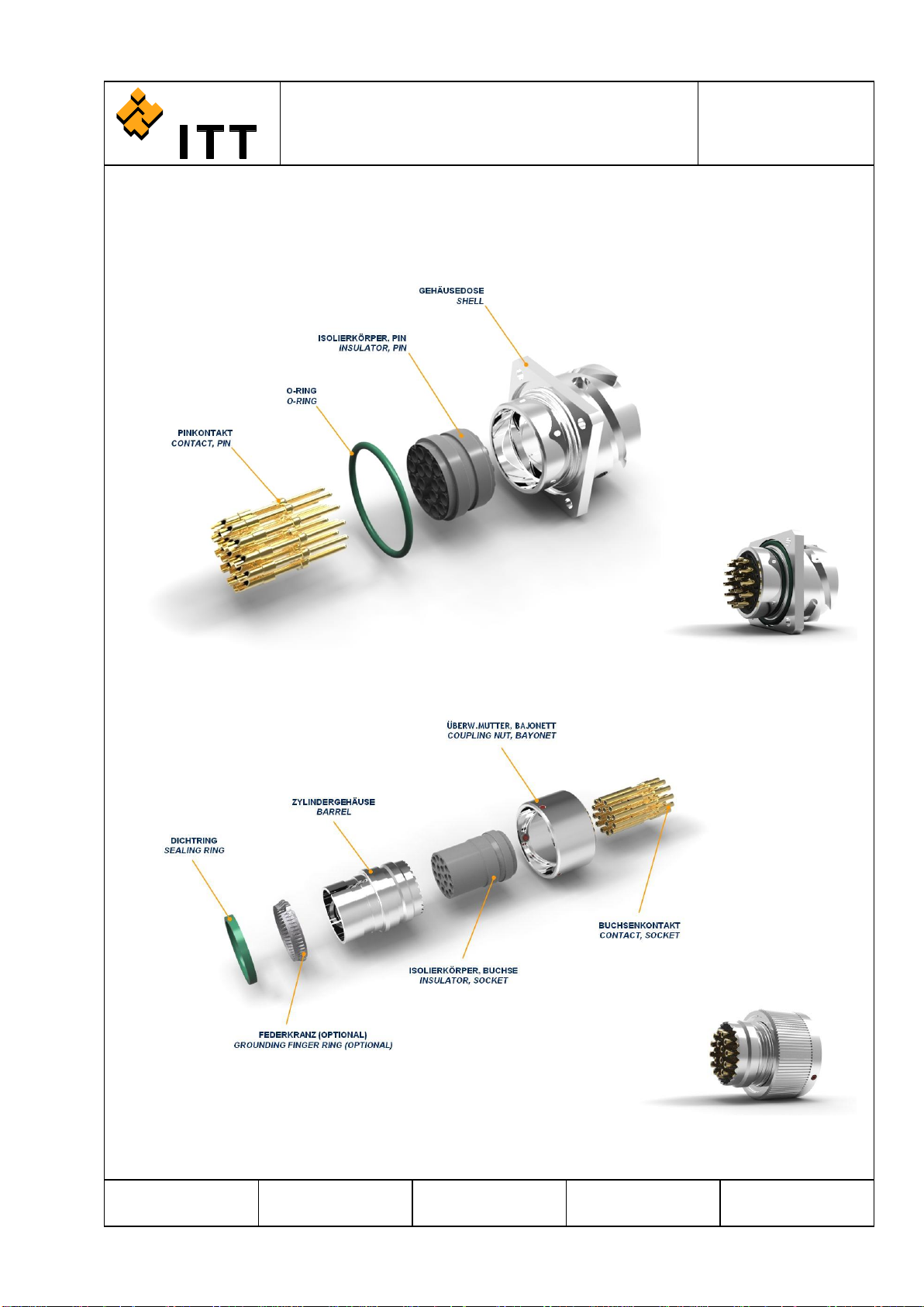
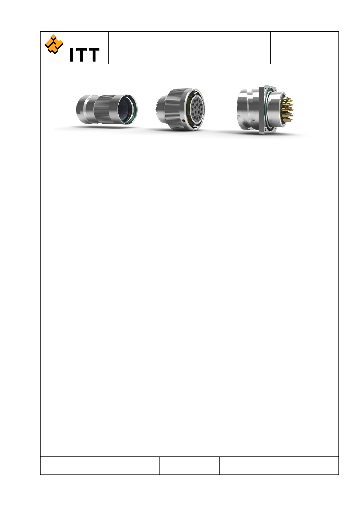
2.1 Explosion View Shell Assembly (Box Mounting Receptacle).....................................3
2.2 Explosion View Barrel Assembly (Straight Plug)........................................................3
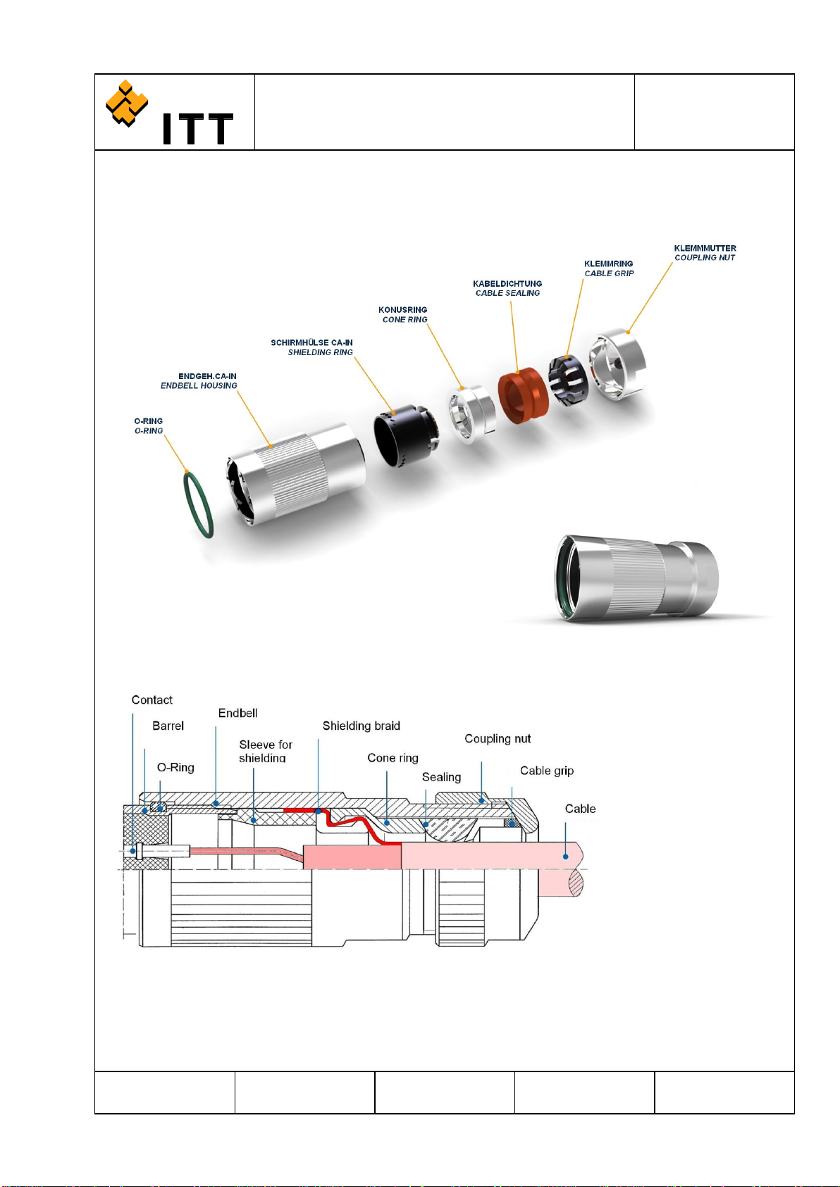
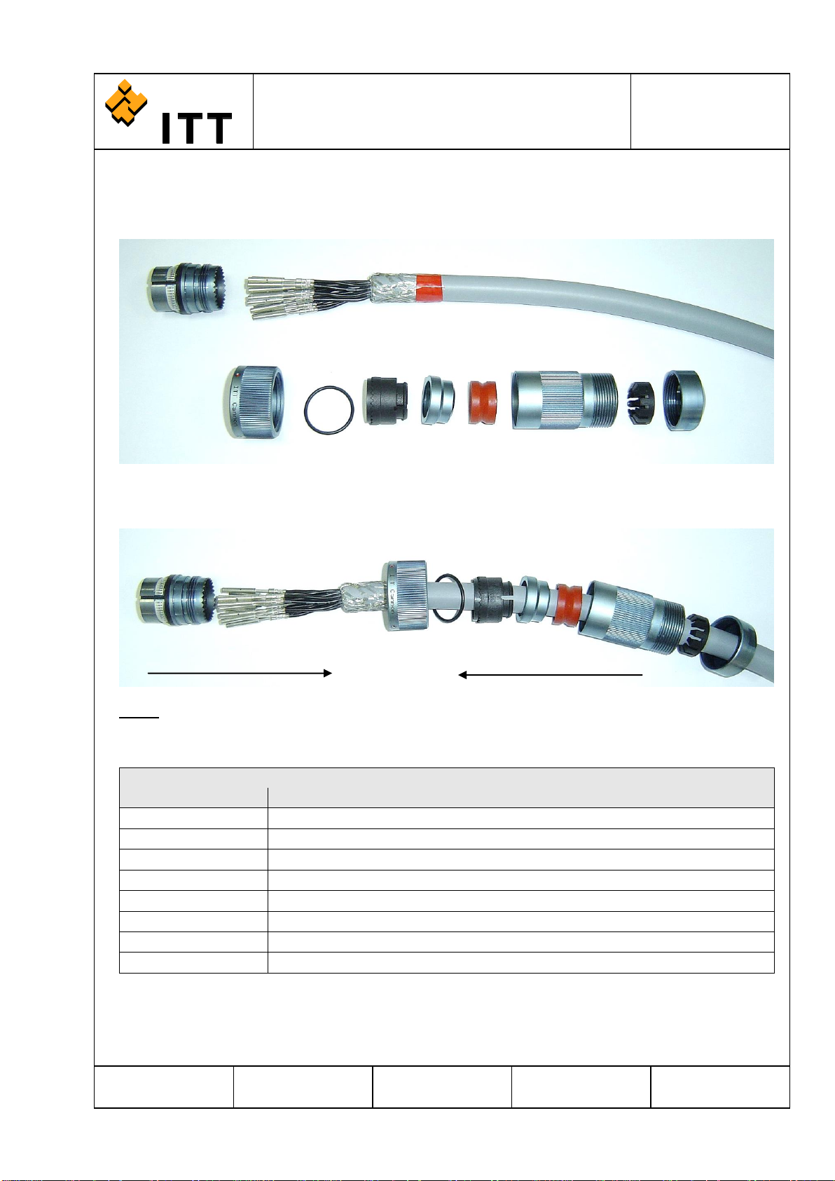
2.3 Explosion View of Universal Endbell / Concept of Shielding......................................4
3Contacts and Assembly Tools .......................................................................5
3.1 Standard Crimp Contacts ...........................................................................................5
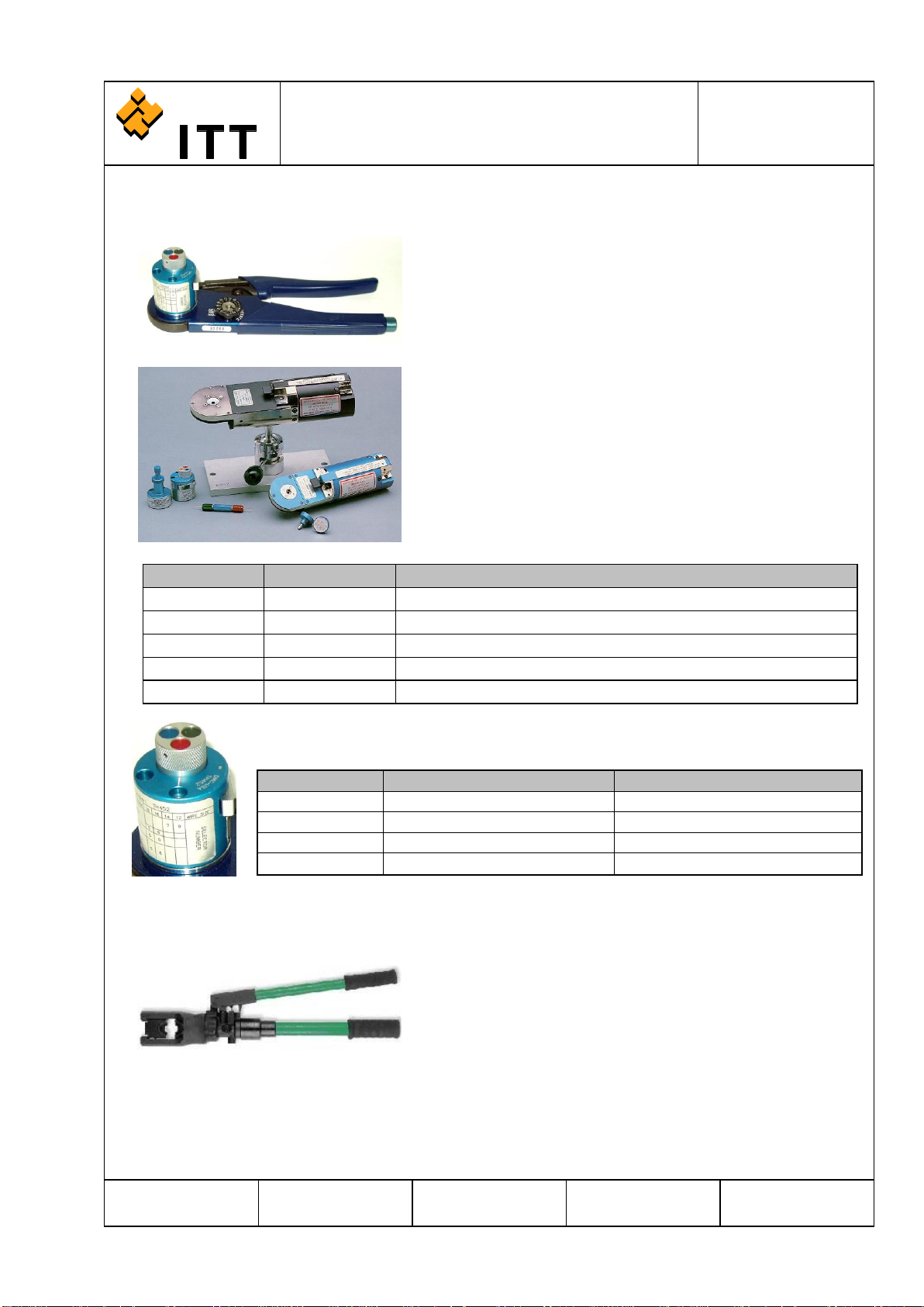
3.2 Crimping Tools............................................................................................................6
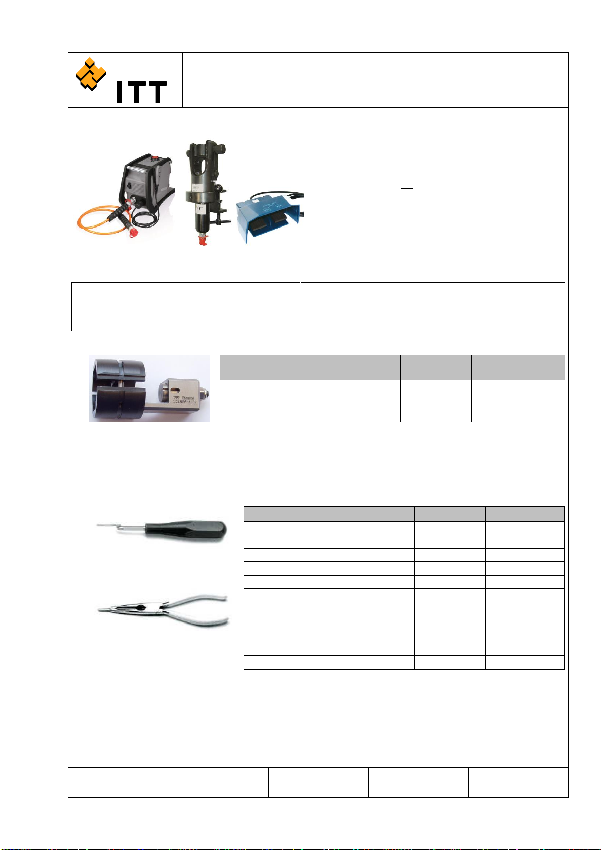
3.3 Insertion Tools ............................................................................................................7
3.4 Extraction Tools..........................................................................................................8
3.5 Pipe Wrench ...............................................................................................................8
3.6 Operating Instructions for Machined Contacts ...........................................................8
4Preparation....................................................................................................9
4.1 Dimensions for Single Conductor, Wire Stripping ......................................................9
4.2 Wire Stripping Length for System Cable ....................................................................9
4.3 Preparation of Shielded System Cable................Fehler! Textmarke nicht definiert.
5Assembly Instructions..................................................................................10
5.1 Overview and Configuration .....................................................................................10
5.2 Insertion of Contacts.................................................................................................11
5.3 Removal of Contacts ................................................................................................13
5.4 Assembly Instruction for the Universal Endbell ........................................................13
6Annex ..........................................................................................................16
6.1 Useful Hints...............................................................................................................16
6.2 Product Safety Information .......................................................................................17
7Brochure......................................................................................................18

CANNON STANDARD page 2 of 20
ASSEMBLY AND WIRING INSTRUCTION
CA-BAYONET IP69K
Circular Connector with Protection Class IP69K
CAS25092E
Bearbeitet:
Geprüft:
Norm:
Änd.-Stand:
Änd.-Datum:
AKU/FA
AKU/FA
G5820W
JPE 18.12.2018
ITT Cannon GmbH, D-71384 Weinstadt
1 General Information
1.1 Scope
This wiring instruction describes the assembly of the Circular Connector with protection class IP69K, a
similar to CA-B connector with a sealing degree up to IP69K.
This connector is interchangeable with the corresponding types of VG95234, as they offer the same
mounting dimensions and contact arrangements.
These connectors are without spring washer and friction ring in the bayonet coupling nut and without
grommet and ferrule.
1.2 Recommended Method of Mounting
In combination with the Universal Endbell and an o-ring between the flange receptacle and wall, the
connector will reach IP68 (16h, 1 bar) and IP69K sealing. The flange receptacle is fixed with screws.
For dimensions of mounting, admissible wall thickness and admissible height of screw head see catalogue
and customer drawings.
1.3 Cross Reference
Further detailed information about wiring instructions, assembly aids, useful hints and other information
see on the Assembly Instruction MS / CA-Bayonet CAS25094E for ITT-Cannon Circular Connectors.

CANNON STANDARD page 3 of 20
ASSEMBLY AND WIRING INSTRUCTION
CA-BAYONET IP69K
Circular Connector with Protection Class IP69K
CAS25092E
Bearbeitet:
Geprüft:
Norm:
Änd.-Stand:
Änd.-Datum:
AKU/FA
AKU/FA
G5820W
JPE 18.12.2018
ITT Cannon GmbH, D-71384 Weinstadt
2 Connector Components
2.1 Explosion View Shell Assembly (Box Mounting Receptacle)
2.2 Explosion View Barrel Assembly (Straight Plug)

CANNON STANDARD page 4 of 20
ASSEMBLY AND WIRING INSTRUCTION
CA-BAYONET IP69K
Circular Connector with Protection Class IP69K
CAS25092E
Bearbeitet:
Geprüft:
Norm:
Änd.-Stand:
Änd.-Datum:
AKU/FA
AKU/FA
G5820W
JPE 18.12.2018
ITT Cannon GmbH, D-71384 Weinstadt
2.3 Explosion View of Universal Endbell / Concept of Shielding

CANNON STANDARD page 5 of 20
ASSEMBLY AND WIRING INSTRUCTION
CA-BAYONET IP69K
Circular Connector with Protection Class IP69K
CAS25092E
Bearbeitet:
Geprüft:
Norm:
Änd.-Stand:
Änd.-Datum:
AKU/FA
AKU/FA
G5820W
JPE 18.12.2018
ITT Cannon GmbH, D-71384 Weinstadt
3 Contacts and Assembly Tools
3.1 Standard Crimp Contacts
Contact Size
Wire Size
mm²
Wire Size
AWG
Pin Contact
Part –No.
A36
Pin Contact
Part –No.
A176
Socket Contact
Part –No.
A36
Socket Contact
Part –No.
A176
10 / 20
0,14 - 0,38
26 / 22
030-8585-004
030-8585-008
031-8554-004
031-8554-008
0,5 - 1,0
20 / 18
030-8585-009
030-8585-011
031-8554-009
031-8554-011
15S / 16S
0,14 - 0,38
26 / 22
030-8586-010
030-8586-016
031-8555-130
031-8555-135
0,3 - 0,6
22 / 20
330-8744-000
330-8744-006
031-8688-110
031-8688-115
0,75 - 1,5
18 / 16
030-8586-000
030-8586-006
031-8555-110
031-8555-115
15 / 16
0,14 - 0,38
26 / 22
030-8587-030
030-8587-036
031-8556-130
031-8556-135
0,3 - 0,6
22 / 20
330-8659-000
330-8659-006
031-8639-120
031-8639-115
0,75 - 1,5
18 / 16
030-8587-000
030-8587-006
031-8556-110
031-8556-115
1,5 - 2,0
16 / 14
030-8587-010
030-8587-016
031-8556-140
031-8556-145
2,0 - 3,0
14 / 12
030-8587-020
030-8587-026
031-8556-120
031-8556-126
25 / 12
0,3 - 0,6
22 / 20
031-8557-040
031-8557-046
0,75 - 1,5
18 / 16
030-8588-010
030-8588-016
031-8557-020
031-8557-026
2,0 - 3,0
14 / 12
030-8588-000
030-8588-006
031-8557-000
031-8557-006
4,0
030-8588-054
030-8588-060
031-8557-010
031-8557-016
6,0
10
031-8557-030
031-8557-036
60 / 100 / 8
2,0 - 3,0
14 / 12
030-8612-010
030-8612-016
031-8519-010
031-8519-016
4,0
030-8612-020
030-8612-026
6,0
10
030-8589-000
030-8589-006
031-8558-000
031-8558-006
8
030-8612-000
030-8612-006
031-8519-000
031-8519-006
10,0
030-8590-000
030-8590-006
031-8559-000
031-8559-006
160 / 4
10,0
030-8591-020
030-8591-026
031-8560-020
031-8560-026
6
030-8613-010
030-8613-016
031-8520-010
031-8520-016
16,0
030-8591-000
030-8591-006
031-8560-000
031-8560-006
4
030-8613-000
030-8613-006
031-8520-000
031-8520-006
500 / 0
16,0
030-8614-030
030-8614-036
031-8521-030
031-8521-036
25,0
4
030-8614-010
030-8614-016
031-8521-010
031-8521-016
35,0
2
030-8614-020
030-8614-026
031-8521-020
031-8521-026
50,0
030-8592-000
030-8592-006
031-8561-000
031-8561-006
0
030-8614-000
030-8614-006
031-8521-000
031-8521-006

CANNON STANDARD page 6 of 20
ASSEMBLY AND WIRING INSTRUCTION
CA-BAYONET IP69K
Circular Connector with Protection Class IP69K
CAS25092E
Bearbeitet:
Geprüft:
Norm:
Änd.-Stand:
Änd.-Datum:
AKU/FA
AKU/FA
G5820W
JPE 18.12.2018
ITT Cannon GmbH, D-71384 Weinstadt
3.2 Crimping Tools
Hand crimping tool M22520/1-01
Order No.: 995-0001-585
This universal tool features just one crimp turret with
different adjustments for crimping contacts.
The tool provides an 8-indent crimp.
Pneumatic crimping tool WA27F-CE
Order No.: 121586-5067
Pneumatic operated crimp tool for higher volume
production. A pedal for foot operation can also be
provided.
The tool provides an 8-indent crimp.
Name
Order-No.
Description
WA27F-CE
121586-5067
Pneumatic crimp tool (AWG12-20)
WA22-CE
121586-5070
Pneumatic crimp tool (AWG20-32)
BM-2
121586-5068
Bench mount
WA10
121586-5069
Foot pedal (without picture)
M22520-3-1
995-0001-684
Gauge
Contact Size
Locator for Pin-Contact
Locator for Socket-Contact
15S / 16S
TH 452 or 600 324
TH 452 or 600 325
15 / 16
TH 452
TH 452
25 / 12
TH 452
TH 452
10 / 20
600 325
600 325
Hydraulic hand crimping tool HPW400U-ITT
Order No.: 121586-5257
Hydraulic hand crimping tool for crimping contacts of size
60/100/8, 160/4 and 500/0.

CANNON STANDARD page 7 of 20
ASSEMBLY AND WIRING INSTRUCTION
CA-BAYONET IP69K
Circular Connector with Protection Class IP69K
CAS25092E
Bearbeitet:
Geprüft:
Norm:
Änd.-Stand:
Änd.-Datum:
AKU/FA
AKU/FA
G5820W
JPE 18.12.2018
ITT Cannon GmbH, D-71384 Weinstadt
Hydraulic-electro tool complete HP700EL-ITT*
Order No.: 121586-5279
*Switch-mode power supply and Lithium-Ion battery
with recharger battery are not included in the delivery!
For more Information, see CAS 25084
Hydraulic tool with electric pump for crimping contacts of
size 60/100/8, 160/4 and 500/0.
The aggregate is connected with a high-pressure hose
to the crimping tool.
Equipment for Hydraulic power unit
Description
ITT Cannon order-nr.
Switch-mode power supply for EHA5 230V
SNT4-ITT
121586-5280
Lithium-Ion battery 18V 3Ah with recharger
LGA4-ITT
121586-5281
Lithium-Ion reserve battery 18V 3Ah
RA4-ITT
121586-5282
Contact Size
Crimp dies for
hydraulic tool
Wrench Size
Locator
60/100/8
CT 121586-5231
5,20
CT 121586-5232
160/4
CT 121586-5230
7,25
500/0
CT 121586-5229
11,40
3.3 Insertion Tools
To insert crimped contacts into the insulator insertion tools are required.
Insertion tool CIT
Description
Name
Order No.
Insertion tool for contact size # 10
CIT-20
121086-3009
Insertion pliers for contact size # 10
CIT-F80-20
121086-0098
Insertion tool for contact size # 16
CIT-16
121086-3008
Insertion pliers for contact size # 16
CIT-F80-16
121086-0097
Insertion tool for contact size # 12
CIT-12
121086-3007
Insertion pliers for contact size # 12
CIT-F80-12
121086-0096
Insertion tool for contact size # 8
CIT-8
121086-0095
Insertion tool for contact size # 4
CIT-4
121086-0094
Insertion tool for contact size # 0
CIT-0
121086-0093
Guide Pin #12
27977-12T8
Guide Pin #16
27977-16T50
Insertion pliers CIT-F80
ATTENTION:
A proper installation is only ensured if the required insertion tools are used.
Guide pins allow easy insertion of socket contacts sizes 15S/16S, 15/16 and 25/12 into the insulator.
Assemble socket contacts only by using guide pins! Without the use of these guide pins during contact
insertion the insulator/contacts are damaged.

CANNON STANDARD page 8 of 20
ASSEMBLY AND WIRING INSTRUCTION
CA-BAYONET IP69K
Circular Connector with Protection Class IP69K
CAS25092E
Bearbeitet:
Geprüft:
Norm:
Änd.-Stand:
Änd.-Datum:
AKU/FA
AKU/FA
G5820W
JPE 18.12.2018
ITT Cannon GmbH, D-71384 Weinstadt
3.4 Extraction Tools
In case a contact has to be exchanged the following extraction tools are to be used:
Extraction Tools
Description
Name
Order No.
extraction tool for contact size # 16
CET-F80-16
121086-0081
extraction tool for contact size # 12
CET-F80-12
121086-0080
extraction tool for contact size # 8
CET-8
121086-0079
extraction tool for contact size # 4
CET-4
121086-0094
extraction tool for contact size # 0
CET-0
121086-0077
ATTENTION:
A proper removing of contacts is only ensured if the required extraction tools are used.
3.5 Pipe Wrench
Soft Jaw Adjustable Pliers
order No.: 550014-1644
for tightening the endbell, housing.
3.6 Operating Instructions for Machined Contacts
1.) strip wires to lengths, for stripping details, see 4.1
2.) open hand tool and insert the contact in the crimp profile
3.) position the stripped cable in the contact
4.) press hand tool to end position
5.) open hand tool and extract the contact, check the contact visually
6.) minimum crimp tensile requirements see DIN EN 60352-2
- there shall be no loose strands out of the crimp section
- the contact must be crimped straight to the cable
- deformed contacts must not be used. In this case crimp again
- while the preparation, strands must not be hurt or cut
1 insulation of cable
2 wire
3 contact
4 inspection hole (wire strands must be visible)
loose wire strand
no wire strand visible

CANNON STANDARD page 9 of 20
ASSEMBLY AND WIRING INSTRUCTION
CA-BAYONET IP69K
Circular Connector with Protection Class IP69K
CAS25092E
Bearbeitet:
Geprüft:
Norm:
Änd.-Stand:
Änd.-Datum:
AKU/FA
AKU/FA
G5820W
JPE 18.12.2018
ITT Cannon GmbH, D-71384 Weinstadt
4 Preparation
4.1 Dimensions for Single Conductor, Wire Stripping
Stripping can be performed either thermically or mechanically. For solder contacts, conductors have to be
pre-tinned. Note: Do not twist conductors used with crimp contacts. Do not touch un-insulated conductors
before crimping. Twisting of conductors and grease or lubricants on the wires causes poor crimp quality.
4.2 Wire Stripping Length for System Cable
4.3 Preparation of Shielded System Cable
Cut off the shielded cable jacked, see 4.2.
Remove the protective foil if necessary.
Turn over braid and fix it with a tape.
Strip the wire insulation cables, see 4.1
Crimp the contacts, see 3.6.
Contact size
Insulation diameter in mm
Wire stripping length in mm
10 / 20
max. 3,0
6,0 +0,5
15 / 16
max. 3,3
6,0 +0,5
25 / 12
max. 4,3
6,0 +0,5
60 / 100 / 8
max. 6,5
11,0 +0,8 -0,4
160 / 4
max. 9,4
11,0 +0,8 -0,4
500 / 0
max. 14,0
13,0 +0,8 -0,4
Shell Size
Length C [mm]
Length B [mm]
Length A [mm]
10SL
32 ±1
ca. 32
see 4.1
14S
34 ±1
ca. 34
see 4.1
16S
34 ±1
ca. 34
see 4.1
18
35 ±1
ca. 35
see 4.1
20
35 ±1
ca. 35
see 4.1
22
43 ±1
ca. 43
see 4.1
24
43 ±1
ca. 43
see 4.1
28
44 ±1
ca. 44
see 4.1

CANNON STANDARD page 10 of 20
ASSEMBLY AND WIRING INSTRUCTION
CA-BAYONET IP69K
Circular Connector with Protection Class IP69K
CAS25092E
Bearbeitet:
Geprüft:
Norm:
Änd.-Stand:
Änd.-Datum:
AKU/FA
AKU/FA
G5820W
JPE 18.12.2018
ITT Cannon GmbH, D-71384 Weinstadt
5 Assembly Instructions
5.1 Overview and Configuration
For short and open cable, the parts can be mounted while assembly from behind.
Pay attention to the correct order and mounting direction of all parts, as pictured.
For longer cable lengths or for applications with already connected cables, slide all parts on the cable
before assembling contacts into barrel and insulator.
Pay attention to the correct order and mounting direction of all parts, as pictured.
Table1: Permitted clamping torque of endbell, housing
ENDBELL HOUSING
shell size
clamping torque
10SL
2,5 –3 Nm
14S
4 –5 Nm
16S
6 –7 Nm
18
6,5 –8 Nm
20
7 –9 Nm
22
8 –10 Nm
24
11 –13 Nm
28
13 –16 Nm
ASSEMBLY DIRECTION
MOUNTING DIRECTION

CANNON STANDARD page 11 of 20
ASSEMBLY AND WIRING INSTRUCTION
CA-BAYONET IP69K
Circular Connector with Protection Class IP69K
CAS25092E
Bearbeitet:
Geprüft:
Norm:
Änd.-Stand:
Änd.-Datum:
AKU/FA
AKU/FA
G5820W
JPE 18.12.2018
ITT Cannon GmbH, D-71384 Weinstadt
Table 2: wrench size and clamping torque of coupling nut
COUPLING NUT
cable sealing area
wrench size
clamping torque
D07
16 mm
1,0 Nm ±0,2
D09
19 mm
1,3 Nm ±0,2
D11
22 mm
1,7 Nm ±0,2
D13
25 mm
2,3 Nm ±0,2
D14
27 mm
3,0 Nm ±0,2
D17
32 mm
3,0 Nm ±0,2
D19
34 mm
3,5 Nm ±0,2
D20
36 mm
3,5 Nm ±0,2
5.2 Insertion of Contacts
1
Plug on and fix the connector for assembling.
Use therefore an assembly adapter or housing.
2
Assemble socket contacts sizes 15S/16S/15/16/12 and 25
only by using guide pins, see 3.3.
Insert guide pin into contact mating side.
3
Moisten the contacts with isopropyl alcohol for easier
contact insertion.
4
Pre-insert the contacts in the insulator.
Contact insertion is started in the center of the insulator.

CANNON STANDARD page 12 of 20
ASSEMBLY AND WIRING INSTRUCTION
CA-BAYONET IP69K
Circular Connector with Protection Class IP69K
CAS25092E
Bearbeitet:
Geprüft:
Norm:
Änd.-Stand:
Änd.-Datum:
AKU/FA
AKU/FA
G5820W
JPE 18.12.2018
ITT Cannon GmbH, D-71384 Weinstadt
5
Place wired contact into insertion tool in a way that
contact, wire and insertion tool are axial to each other. Use
the correct insertion tool (see 3.3).
Insert contacts by applying slow, continuous pressure, until
it snaps into its position.
Do not install damaged or bent contacts! If a contact is
damaged during the insertion this contact has to be
removed. A new contact has to be installed.
6
After insertion operation remove the insertion tool
cautiously.
Avoid any movement of the tool during the insertion
process which is not axial to the contact / insulator.
7
After insertion of contacts remove the guide pins if
necessary (socket contacts 15S/16S/15/16/12and 25 only).
After insertion of the contacts, check connector on the
mating side to ensure that all contacts are on the same
level.
8
Connector with fully assembled contacts.

CANNON STANDARD page 13 of 20
ASSEMBLY AND WIRING INSTRUCTION
CA-BAYONET IP69K
Circular Connector with Protection Class IP69K
CAS25092E
Bearbeitet:
Geprüft:
Norm:
Änd.-Stand:
Änd.-Datum:
AKU/FA
AKU/FA
G5820W
JPE 18.12.2018
ITT Cannon GmbH, D-71384 Weinstadt
5.3 Removal of Contacts
1. All accessories are removed in reversed direction as described in the assembly instruction.
2. Use the correct removal tool as described on 3.4.
3. Place tool from the mating side parallel to their axis over the socket or pin contact. Apply smooth and
continuous pressure toward the rear end of the connector to push contact out of the insulator. The
operation is terminated as soon as the shoulder of the tool butts against the front of the insulator.
4. Pull tool carefully out of the connector.
Extraction Tools.
5.4 Assembly Instruction for the Universal Endbell
1
Make sure, that the sealing ring is mounted and greased.
2
Move the coupling nut on the barrel.
Mount the O-ring on the barrel.
Pay attention that the O-ring is not twisted (water
tightness!).
3
Move the shielding ring to the barrel, pay attention to the
tooth pitch.
Remove the tape
Disentangle the shielding braid and arrange it evenly round
over the shielding ring.

CANNON STANDARD page 14 of 20
ASSEMBLY AND WIRING INSTRUCTION
CA-BAYONET IP69K
Circular Connector with Protection Class IP69K
CAS25092E
Bearbeitet:
Geprüft:
Norm:
Änd.-Stand:
Änd.-Datum:
AKU/FA
AKU/FA
G5820W
JPE 18.12.2018
ITT Cannon GmbH, D-71384 Weinstadt
4
Move the cone ring on the shielding ring.
Mount the cone ring into position (snap-on connection).
Pay attention that the end of the cable jacket is closed to
the cone ring.
5
Cut the shielding braid according to picture, use a scissors
or wire cutter.
6
Move the cable sealing to the cone ring.
Lubricate the O-ring with petrolatum (jelly), Vaseline®
7
Move the endbell, housing to the barrel.
8
Screw the endbell, housing over the O-ring of the barrel
(finger tight).
TIPP: As installation support the flange shell can be used.
Move the cable grip into the endbell, housing. Pay
attention that the mounting direction is according to the
picture.
9
Lubricate the thread of the endbell housing.
Screw the coupling nut on the endbell, housing softly.
10
Tighten the endbell, housing and note the permitted
torque, see 5.1, table 1.
While tightening the endbell, take care that the cable is
secured against twisting.
TIPP: Use the mounting adapter or flange shell.

CANNON STANDARD page 15 of 20
ASSEMBLY AND WIRING INSTRUCTION
CA-BAYONET IP69K
Circular Connector with Protection Class IP69K
CAS25092E
Bearbeitet:
Geprüft:
Norm:
Änd.-Stand:
Änd.-Datum:
AKU/FA
AKU/FA
G5820W
JPE 18.12.2018
ITT Cannon GmbH, D-71384 Weinstadt
11
Mount the coupling nut with an open-end wrench, wrench
size, see 5.1, table 2.
Tighten the coupling nut and note the permitted torque,
see 5.1, table 2.
Use screw locking varnish to prevent loosening of the
clamping nut if used with high vibration applications.
12
The connector is ready assembled now.

CANNON STANDARD page 16 of 20
ASSEMBLY AND WIRING INSTRUCTION
CA-BAYONET IP69K
Circular Connector with Protection Class IP69K
CAS25092E
Bearbeitet:
Geprüft:
Norm:
Änd.-Stand:
Änd.-Datum:
AKU/FA
AKU/FA
G5820W
JPE 18.12.2018
ITT Cannon GmbH, D-71384 Weinstadt
6 Annex
6.1 Useful Hints
Keep hands, working place and connectors clean and free of any grease.
Check tools, connectors, accessories, cable sizes and other aids for correct part number and size.
Cable/wire cutting and stripping
Cut wire/cable in a way that a proper and even surface is achieved. Avoid indents, marks, or similar in the cutting area.
During stripping of individual wires observe the stripping length depending on a contact size.
Prevent any damage of individual strands.
For solder connections pre-tin the conductor over the complete stripping length.
Keep time of soldering the conductors to contacts already installed in the insulator as short as possible in order to prevent any
damage to the insulator which may be caused by over-heating.
To obtain good crimp connections please follow the rules:
a) Use correct crimp tool with correct locator
b) When terminating contacts sizes 60/100, 160 and 500 with the hydraulic crimp tool finalize crimping operations without
interruption
c) Use correct insertion tool for individual contacts
d) Stripped conductors have to be crimped in a proper way.
The following simple tests can be made:
Visual:
Contacts are damaged during crimping (torn, bent, etc.) All wire strands must be inserted on the contact.
Mechanical:
Pull the terminated wire to check if crimp connection is properly made.
Insert contacts straight into insulator
Do not insert damage contacts
Maintain steady pressure when contacts are inserted
Do not use damaged insulators or grommets
Before insertion of wired contacts, slide hardware (grommet, endbell or cable clamp etc.) in proper order over the wire bundle.
Please assure that the correct conductor is inserted into the correct cavity of the grommet.
Isopropyl alcohol facilitates insertion of cable into grommet.
Apply Isopropyl alcohol to the appropriate insulator cavity prior to insertion of contact.
Inspect visually, if all socket or pin contacts are inserted properly, i.e. whether the mating ends of the contacts are all on same level.
Mate shells resp. barrels with coupling nuts in correct assembly adapter.
Do not harness without using assembly adapters or mating connectors.
If required, lock endbell with Loctite or other locking compound. Loctite is to be stored at room temperature preferably below 20°C.
Insert contacts from the rear and release them from the mating face of the connector.
Extract contact only with the correct tool.
Note: according to weight and tension (vibration, acceleration) the cable has to be seized and fixed at the suitable place.

CANNON STANDARD page 17 of 20
ASSEMBLY AND WIRING INSTRUCTION
CA-BAYONET IP69K
Circular Connector with Protection Class IP69K
CAS25092E
Bearbeitet:
Geprüft:
Norm:
Änd.-Stand:
Änd.-Datum:
AKU/FA
AKU/FA
G5820W
JPE 18.12.2018
ITT Cannon GmbH, D-71384 Weinstadt
6.2 Product Safety Information
1. MATERIAL CONTENT AND PHYSICAL FORM
Electrical connectors do not usually contain hazardous materials. They contain conducting and non-conducting materials and can be
divided into two groups.
a) Printed circuit types and low cost audio types which employ all plastic insulators and casings.
b) Rugged, Fire Barrier and High Reliability types with metal casings and either natural rubber, synthetic rubber, plastic or glass
insulating materials. Contact materials vary with type of connector and also application and are usually manufactured from either:
Copper, copper alloys, nickel, alumel, chromel or steel. In special applications, other alloys may be specified.
2. FIRE CHARACTERISTICS AND ELECTRIC SHOCK HAZARD
There is no fire hazard when the connector is correctly wired and used within the specified parameters. Incorrect wiring or assembly
of the connector or careless use of metal tools or conductive fluids, or transit damage to any of the component parts may cause
electric shock or burns. Live circuits must not be broken by separating mated connectors as this may cause arcing, ionization and
burning. Heat dissipation is greater at maximum resistance in a circuit. Hot spots may occur when resistance is raised locally by
damage, e.g. cracked or deformed contacts, broken strands of wire. Local overheating may also result from the use of the incorrect
application tools or from poor quality soldering or slack screw terminals. Overheating may occur if the ratings in the product Data
Sheet/Catalog are exceeded and can cause breakdown of insulation and hence electric shock. If heating is allowed to continue it
intensifies by further increasing the local resistance through loss of temper of spring contacts, formation of oxide film on contacts and
wires and leakage currents through carbonization of insulation and tracking paths. Fire can then result in the presence of
combustible materials and this may release noxious fumes. Overheating may not be visually apparent. Burns may result from
touching overheated components.
3. HANDLING
Care must be taken to avoid damage to any component parts of electrical connectors during installation and use. Although there are
normally no sharp edges, care must be taken when handling certain components to avoid injury to fingers. Electrical connectors may
be damaged in transit to the customers, and damage may result in creation of hazards. Products should therefore be examined prior
to installation/use and rejected if found to be damaged.
4. DISPOSAL
Incineration of certain materials may release noxious or even toxic fumes.
5. APPLICATION
Connectors with exposed contacts should not be selected for use on the current supply side of an electrical circuit, because an
electric shock could result from touching exposed contacts on an unmated connector. Voltages in excess of 30 V ac or 42.5 V dc are
potentially hazardous and care should be taken to ensure that such voltages cannot be transmitted in any way to exposed metal
parts of the connector body. The connector and wiring should be checked, before making live, to have no damage to metal parts or
insulators, no solder blobs, loose strands, conducting lubricants, swarf, or any other undesired conducting particles. Circuit
resistance and continuity check should be made to make certain that there are no high resistance joints or spurious conducting
paths. Always use the correct application tools as specified in the Data Sheet/Catalog. Do not permit untrained personnel to wire,
assemble or tamper with connectors. For operation voltage please see appropriate national regulations.
IMPORTANT GENERAL INFORMATION
(i) Air and creepage paths/Operating voltage:
The admissible operating voltages depend on the individual applications and the valid national and other applicable safety
regulations. For this reason the air and creepage path data are only reference values. Observe reduction of air and creepage paths
due to PC board and/or harnessing.
(ii) Temperature:
All information given are temperature limits. The operation temperature depends on the individual application.
(iii) Other important information:
Cannon continuously endeavors to improve their products. Therefore, Cannon products may deviate from the description, technical
data and shape as shown in this assembly and wiring instruction. ITT Interconnect Solutions, a Division of ITT Corporation
manufactures the highest quality products available in the marketplace; however these products are intended to be used in
accordance with the specifications in this publication. Any use or application that deviates from the stated operating specifications is
not recommended and may be unsafe. No information and data contained in this publication shall be construed to create any liability
on the part of Cannon. Any new issue of this publication shall automatically invalidate and supersede any and all previous issues.

CANNON STANDARD page 18 of 20
ASSEMBLY AND WIRING INSTRUCTION
CA-BAYONET IP69K
Circular Connector with Protection Class IP69K
CAS25092E
Bearbeitet:
Geprüft:
Norm:
Änd.-Stand:
Änd.-Datum:
AKU/FA
AKU/FA
G5820W
JPE 18.12.2018
ITT Cannon GmbH, D-71384 Weinstadt
7 Brochure
Endbell: Universal Endbell
Shielding: Yes
Sealing (*): IP67, IP68, IP69K
Größe ØA B C ØD
Gweinde max min max
#10SL D07 18 9/16-24UNEF-2B 65 17,9 4,5 - 7,2 mm
#14S D07 22 3/4-20UNEF-2B 67 17,9 4,5 - 7,2 mm
D09 22 3/4-20UNEF-2B 67 21,0 6,5 - 9,3 mm
D11 22 3/4-20UNEF-2B 67 27,4 8,0 - 10,3 mm
#16S D09 27 7/8-20UNEF-2B 68 21,0 6,5 - 9,3 mm
D11 27 7/8-20UNEF-2B 68 27,4 8,0 - 10,3 mm
D13 27 7/8-20UNEF-2B 68 27,4 9,0 - 12,5 mm
#18 D07 28 1-20UNEF-2B 68 17,9 4,5 - 7,2 mm
D09 28 1-20UNEF-2B 68 21,0 6,5 - 9,3 mm
D11 28 1-20UNEF-2B 68 27,4 8,0 - 10,3 mm
D13 28 1-20UNEF-2B 68 27,4 9,0 - 12,5 mm
D14 28 1-20UNEF-2B 68 30,0 11,5 - 14,2 mm
#20 D07 32 1 1/8-18UNEF-2B 70 17,9 4,5 - 7,2 mm
D09 32 1 1/8-18UNEF-2B 70 21,0 6,5 - 9,3 mm
D11 32 1 1/8-18UNEF-2B 70 27,4 8,0 - 10,3 mm
D13 32 1 1/8-18UNEF-2B 70 27,4 9,0 - 12,5 mm
D14 32 1 1/8-18UNEF-2B 70 30,0 11,5 - 14,2 mm
D17 32 1 1/8-18UNEF-2B 70 33,6 14,5 - 16,6 mm
#22 D13 37 1 1/4-18UNEF-2B 75 27,4 9,0 - 12,5 mm
D14 37 1 1/4-18UNEF-2B 75 30,0 11,5 - 14,2 mm
D17 37 1 1/4-18UNEF-2B 75 33,6 14,5 - 16,6 mm
D19 37 1 1/4-18UNEF-2B 75 36,0 16,1 - 18,4 mm
#24 D14 41 1 3/8-18UNEF-2B 78 30,0 11,5 - 14,2 mm
D17 41 1 3/8-18UNEF-2B 78 33,6 14,5 - 16,6 mm
D19 41 1 3/8-18UNEF-2B 78 36,0 16,1 - 18,4 mm
#28 D14 47 1 5/8-18UNEF-2B 82 30,0 11,5 - 14,2 mm
D17 47 1 5/8-18UNEF-2B 82 33,6 14,5 - 16,6 mm
D19 47 1 5/8-18UNEF-2B 82 36,0 16,1 - 18,4 mm
D20 47 1 5/8-18UNEF-2B 82 38,2 17,8 - 20,0 mm
(*) Die jeweilige Dichtheitsklasse wird im gekuppelten Zustand erreicht.
ØE Dichtbereich

CANNON STANDARD page 19 of 20
ASSEMBLY AND WIRING INSTRUCTION
CA-BAYONET IP69K
Circular Connector with Protection Class IP69K
CAS25092E
Bearbeitet:
Geprüft:
Norm:
Änd.-Stand:
Änd.-Datum:
AKU/FA
AKU/FA
G5820W
JPE 18.12.2018
ITT Cannon GmbH, D-71384 Weinstadt
Wire Stripping Length for System Cable
Table 1
Shell
Size
Length C
[mm]
Length B
[mm]
Length A
[mm]
10SL
32 ±1
ca. 32
see table2
14S
34 ±1
ca. 34
see table2
16S
34 ±1
ca. 34
see table2
18
35 ±1
ca. 35
see table2
20
35 ±1
ca. 35
see table2
22
43 ±1
ca. 43
see table2
24
43 ±1
ca. 43
see table2
28
44 ±1
ca. 44
see table2
Table 2
Contact
size
Insulation diameter
in mm
Wire stripping length
in mm
10 / 20
max. 3,0
6,0 +0,5
15 / 16
max. 3,3
6,0 +0,5
25 / 12
max. 4,3
6,0 +0,5
60 / 100 / 8
max. 6,5
11,0 +0,8 -0,4
160 / 4
max. 9,4
11,0 +0,8 -0,4
500 / 0
max. 14,0
13,0 +0,8 -0,4
Clamping Torque for Endbell, Housing and Coupling Nut
Table 3
Shell
ENDBELL HOUSING
Size
Clamping Torque
10SL
2,5 –3 Nm
14S
4 –5 Nm
16S
6 –7 Nm
18
6,5 –8 Nm
20
7 –9 Nm
22
8 –10 Nm
24
11 –13 Nm
28
13 –16 Nm
Table 4
COUPLING NUT
Cable Sealing Area
Wrench Size
Clamping Torque
D07
16 mm
1,0 Nm ±0,2
D09
19 mm
1,3 Nm ±0,2
D11
22 mm
1,7 Nm ±0,2
D13
25 mm
2,3 Nm ±0,2
D14
27 mm
3,0 Nm ±0,2
D17
32 mm
3,0 Nm ±0,2
D19
34 mm
3,5 Nm ±0,2
D20
36 mm
3,5 Nm ±0,2

CANNON STANDARD page 20 of 20
ASSEMBLY AND WIRING INSTRUCTION
CA-BAYONET IP69K
Circular Connector with Protection Class IP69K
CAS25092E
Bearbeitet:
Geprüft:
Norm:
Änd.-Stand:
Änd.-Datum:
AKU/FA
AKU/FA
G5820W
JPE 18.12.2018
ITT Cannon GmbH, D-71384 Weinstadt
Change history
Index
Change no.
Description of change
Date
D
5438W
Hydraulic-electro tool complete replaced by new version.
Semi-automatic crimp station removed. Change history added.
Added reference to CAS 25084 in 4.2.
10.05.2017
E
5590W
Remarks to glue the O-ring to the barrel size 10SL removed in
chapter 5.1, 5.4 and 7.
15.01.2018
F
5350W
Wire stripping length for contact size 10/20 in section 4.1 and 7
changed; 3.1 new
3.1 part numbers for size 10/20 changed:
030-8585-010 changed to 0 30-8585-004,
030-8585-000 changed to 030-8585-009,
030-8585-016 changed to 030-8585-008,
030-8585-006 changed to 030-8585-011,
031-8554-010 changed to 031-8554-004,
031-8554-000 changed to 031-8554-009,
031-8554-016 changed to 031-8554-008,
031-8554-006 changed to 031-8554-011
18.01.2018
G
5820W
The sizes 16S and 24, as well as the cable modifications for the
sizes 16S, 18 and 24 were added in sections 4.1, 5.1 and 7.
18.12.2018
This manual suits for next models
1
Table of contents
Other ITT Cables And Connectors manuals
Popular Cables And Connectors manuals by other brands

PCB Piezotronics
PCB Piezotronics 010G05 Installation and operating manual

StarTech.com
StarTech.com HDMI-SPLITTER-4K60UP quick start guide

Reinhausen
Reinhausen c.a.p.t. 099 Series Installation manual & maintenance

Staubli
Staubli PV-KBT4/5 UR Series Assembly instructions

Philips
Philips SWV3511NZ Specifications

ATZ
ATZ HDMI-14TW manual