ITT PS-00097-CU User manual

CONNECTION CABLE
Operating Instruction Connection Cable; Rev. - Page 1of 29
OPERATING INSTRUCTIONS
PS-00097-CU
CONNECTION CABLE
MODE 3 CASE B; TYPE2 –TYPE2
AC - Electric Vehicle Charging Solution

CONNECTION CABLE
Page 2of 29 Operating Instruction Connection Cable, Rev. -
IMPRINT
ITT Cannon VEAM Italia S.r.l.
Corso Europa 41/43
20045 Lainate (MI), Italy
Phone: +39 02 938721
ittcannon.com
2023 © ITT Cannon
All rights reserved
INFORMATION!
This publication is an integral part of the Technical
Documentation for the “AC e-mobility Interconnect Solution”
and is protected by copyright.
Any use beyond the limits of copyright law without written
permission is forbidden and subject to penalty.
This also applies to reproductions, translations, microfilms, as
well as storage and processing in electronic media. Violations
will give rise to a right to compensation.

CONNECTION CABLE
Operating Instruction Connection Cable; Rev. - Page 3of 29
REVISION OVERVIEW
Revision
Date
Description
Author
-
31.05.2023
New doc no. for PS-00055-CU
Revised and updated
F. Albrecht
Table 1: Revision table

Page 4of 29 Operating Instruction Connection Cable, Rev. -
TABLE OF CONTENTS
Imprint...........................................................................................................2
Revision overview ..........................................................................................3
Table of contents ...........................................................................................4
Declaration of Conformity..............................................................................5
Information about the document...................................................................6
Type designation............................................................................................7
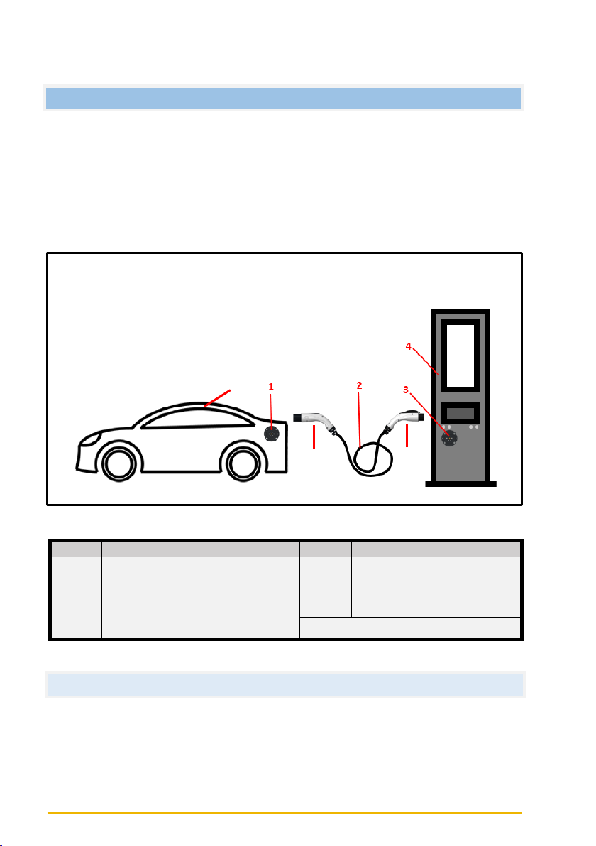
Overview and description ..............................................................................8
User Instruction ..................................................................................................8
Charging Modes and description....................................................................9
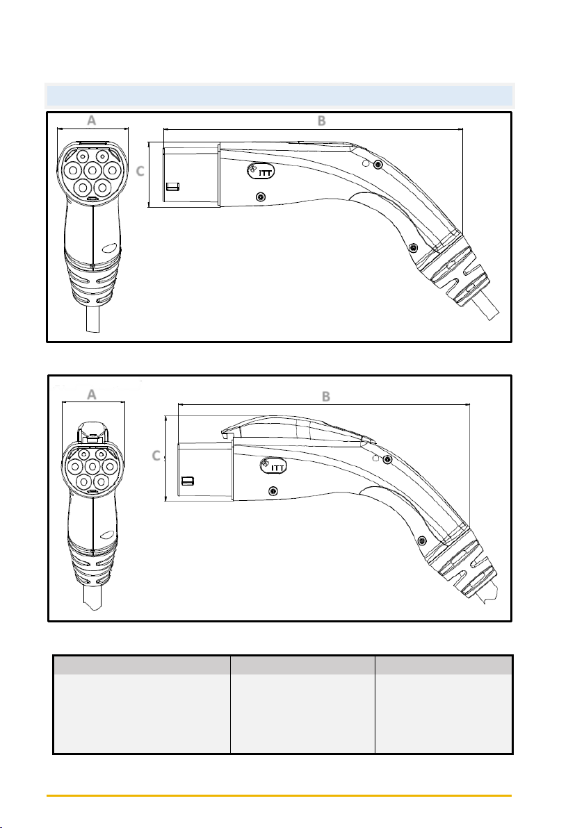
Connector Dimensions (PLUG) ECCE & GBCE ...................................................10
Connector Dimensions (Connector) EJCV & ECCV ............................................11
Connector Dimensions (Connector) GBCV .......................................................12
General data of ECCE (Plug) & EJCV (Connector)..............................................13
General data of ECCE (Plug) & ECCV (Connector).............................................14
General data of ECCE (Plug) & GBCV (Connector) ............................................15
General data of GBCE (Plug) & EJCV (Connector).............................................16
General data of GBCE (Plug) & ECCV (Connector) ............................................17
General data of GBCE (Plug) & GBCV (Connector)............................................18
Connector marking ...........................................................................................19
Transportation and Storage .........................................................................21
Delivery.............................................................................................................21
Transportation..................................................................................................22

Operating Instruction Connection Cable; Rev. - Page 5of 29
Storage..............................................................................................................22
Connector Operation................................................................................... 23
Transportation and Storage..............................................................................26
Cleaning the Components.................................................................................28
Disposal.............................................................................................................28
DECLARATION OF CONFORMITY
The Tethered lead Charging Cable is in conformity with the relevant harmoniza-
tion legislation.
EU-DECLARATION OF CONFORMITY and UK-DECLARATION OF CONFORMITY are
available on request and could be downloaded from ITT Cannon homepage:
ittcannon.com/evc

Page 6of 29 Operating Instruction Connection Cable, Rev. -
INFORMATION ABOUT THE DOCUMENT
This document contains important information about transportation, assembly
(function), installation, operation, and maintenance of the Connection Cable.
General information, technical characteristics, certification and declaration of
conformity of this product is descripted in the product specification.
CAUTION!
Non-adherence to the information contained in this document may re-
sult in injury or property damage!
Always observe and comply with the warning and safety no-
tices in this document. They are the basic prerequisites for
safe execution of the tasks described in this document. If han-
dled improperly contrary to the specifications in this docu-
ment, the manufacturer will not accept any liability or offer
any refund or compensation. In this case, the operator alone
shall be responsible.
Modifications (of any kind) to components of the Connection
Cable are strictly forbidden!

Operating Instruction Connection Cable; Rev. - Page 7of 29
TYPE DESIGNATION
The Connection Cable described herein is a connector system
consisting of:
Featuring a charging cable, an Equipment Plug and a Vehicle Connector. When op-
erated at a charging station, or wall box, in charging mode 3 case B, a charging
current of up to 63A (depending on the corresponding Connection Cable) can be
supplied for charging electric and hybrid vehicles.
The Connection Cable has been designed and manufactured using state-of-the-art
techniques and in accordance with approved safety regulations. Nevertheless,
when not used as intended, risks for the user or third parties may still arise, or the
Connection Cable and other material assets may be damaged.
Intended use includes:
•Application within the stated performance limits.
•Application when in efficient working order without any damage.
•Application only in conjunction with designated vehicle inlets according to
IEC 62196.
•Application only in conjunction with charging stations according to
IEC 61851.
Equipment Plug
Vehicle Connector
ECCE Type 2 (acc. to IEC 62196-3)
-EJCV Type 1 (acc. to IEC 62196)
-ECCV Type 2 (acc. to IEC 62196)
-GBCV (acc. to GB/T 20234)
GBCE (acc. to GB/T 20234 MODE 3)
-EJCV Type 1 (acc. to IEC 62196)
-ECCV Type 2 (acc. to IEC 62196)
-GBCV (acc. to GB/T 20234)
and

Page 8of 29 Operating Instruction Connection Cable, Rev. -
Figure 1: Overview of the individual components
OVERVIEW AND DESCRIPTION
The Connection Cable consists of the following individual components which -
within the overall scope of functioning - represent the interface between the
charging infrastructure and the vehicle being charged:
•Connector system Plug - ECCE Type 2 or GBCE
•Connector system Connector - ECCV Type 2, EJCV Type 1 or GBCV
•Charging cable
Item
Designation
Item
Designation
1
Charging inlet (car)
5
Charging plug (car)
2
Connection Cable
6
Charging connector (station)
3
Charging outlet (station)
7
Electric vehicle
4
Charging station
USER INSTRUCTION
The 2-end connecting cable is used to connect the electric vehicle (7) and the
charging station (4). The charging plug (car) (5) must be plugged into the charging
inlet (car) (1) and the charging connector (station) (6) into the charging outlet
(station) (3). The charging cable (2) must not be stretched and has to hang.
Table 2: Individual Components Designation
5
6
7

Operating Instruction Connection Cable; Rev. - Page 9of 29
CHARGING MODES AND DESCRIPTION
In charging mode 3B, a mobile AC charging cable is required
(Connection Cable), which has a connector at both ends. One end, the ve-
hicle charging plug, is inserted into the inlet of the vehicle. The other end
of the charging cable, the infrastructure charging connector, is inserted
into the charging socket of the charging station.
Charging mode 3B
Figure 2: Description and application of Charging mode 3B

Page 10 of 29 Operating Instruction Connection Cable, Rev. -
Figure 3: ECCE (Plug) Connector
CONNECTOR DIMENSIONS (PLUG) ECCE & GBCE
Table 3: Connector Dimensions for (Plug) ECCE and GBCE
Description
ECCE
GBCE
Width (A)
~ 58 mm
~ 58 mm
Length (B)
~ 243 mm
~ 243 mm
Height (C)
~ 52 mm
~ 70 mm
Weight (without cable)
~ 0.5 kg
~ 0.5 kg
B
A
B
A
C
ECCE
C
GBCE
Figure 4: GBCE (Plug) Connector

Operating Instruction Connection Cable; Rev. - Page 11 of 29
Figure 5: EJCV (Connector) Connector
CONNECTOR DIMENSIONS (CONNECTOR) EJCV & ECCV
Table 4: Connector Dimensions for (Plug) EJCV and ECCV
Description
EJCV
ECCV
Width (A)
~ 58 mm
~ 70 mm
Length (B)
~ 231 mm
~ 234 mm
Height (C)
~ 68 mm
~ 63 mm
Weight (without cable)
~ 0.5 kg
~ 0.5 kg
B
EJCV
C
ECCV
Figure 6: ECCV (Connector) Connector
A
B
A
C

Page 12 of 29 Operating Instruction Connection Cable, Rev. -
Figure 7: GBCV (Connector) Connector
CONNECTOR DIMENSIONS (CONNECTOR) GBCV
Table 5: Connector Dimensions for (Connector) GBCV and J2CE
Description
GBCV
J2CE
Width (A)
~ 58 mm
~ 58 mm
Length (B)
~ 232 mm
~ 231 mm
Height (C)
~70 mm
~68 mm
Weight (without cable)
~ 0.5 kg
~0.5 kg
B
A
GBCV
C

Operating Instruction Connection Cable; Rev. - Page 13 of 29
GENERAL DATA OF ECCE (PLUG) & EJCV (CONNECTOR)
Description
Value
Applied standard
IEC 62196-1 & 2
Charging mode
Mode 2 & 3B (IEC 61851)
Max. operating temperature
+50 °C
Min. operating temperature
-30 °C
Max. operating voltage
250 V-AC
Rated current
20 A, 32 A
Max. application height above sea level
4000 m
Degree of protection
IP44
Item
Designation
Item
Designation
1
L1 (Line 1)
8
Connection Cable
2
PP/CS/CC (Proximity)
9
PP/CS/CC (Proximity)
3
CP (Control Pilot)
10
L1 (Line 1)
4
N (Neutral)
11
N (Neutral)
5
Vacant, not required
12
CP (Control Pilot)
6
PE
13
PE
7
Vacant, not required
-
Table 7: Contact arrangement for ECCE & EJCV Connection Cable
7
6
5
13
Figure 8: Connector Overview, left side: ECCE (Plug); right side: EJCV (Connector)
1
2
3
4
Table 6: Specifications for ECCE & EJCV Connection Cable
8
9
10
11
12

Page 14 of 29 Operating Instruction Connection Cable, Rev. -
GENERAL DATA OF ECCE (PLUG) & ECCV (CONNECTOR)
Description
Value
Applied standard
IEC 62196-2
Charging mode
Mode 2 & 3B (IEC 61851)
Max. operating temperature
+50 °C
Min. operating temperature
-30 °C
Max. operating voltage
250 V-AC (Single phase)
480 V-AC (Three phase)
Rated current
20 A, 32 A, 63A
Max. application height above sea level
4000 m
Degree of protection
IP44
Item
Designation
Item
Designation
1
L1 (Line 1)
8
Connection Cable
2
PP/CS/CC (Proximity)
9
N (Neutral)
3
CP (Control Pilot)
10
CP (Control Pilot)
4
N (Neutral)
11
PP/CS/CC (Proximity)
5
L2 (Line 2) for 3Phase only
12
L1 (Line 1)
6, 14
PE
13
L3 (Line 3) for 3Phase only
7
L3 (Line 3) for 3Phase only
15
L2 (Line 2) for 3Phase only
Table 9: Contact arrangement for ECCE & ECCV Connection Cable
1
2
3
4
6
7
5
8
10
9
11
12
14
15
13
Figure 9: Connector Overview, left side: ECCE (Plug); right side: ECCV (Connector)
Table 8: Specifications for ECCE & ECCV Connection Cable

Operating Instruction Connection Cable; Rev. - Page 15 of 29
GENERAL DATA OF ECCE (PLUG) & GBCV (CONNECTOR)
Description
Value
Applied standard
IEC 62196-2 & GB-T 20234
Charging mode
Mode 2 & 3B (IEC 61851)
Max. operating temperature
+50 °C
Min. operating temperature
-30 °C
Max. operating voltage
250 V-AC (Single phase)
480 V-AC (Three phase)
Rated current
10 A, 16 A, 32 A
Max. application height above sea level
4000 m
Degree of protection
IP44
Table 11: Contact arrangement for ECCE & GBCV Connection Cable
Item
Designation
Item
Designation
1
L1 (Line 1)
8
Connection Cable
2
PP/CS/CC (Proximity)
9
L1 (Line 1)
3
CP (Control Pilot)
10
PP/CS/CC (Proximity)
4
N (Neutral)
11
CP (Control Pilot)
5
L2 (Line 2) for 3Phase only
12
N (Neutral)
6, 14
PE
13
L2 (Line 2) for 3Phase only
7
L3 (Line 3) for 3Phase only
15
L3 (Line 3) for 3Phase only
Table 10: Specifications for ECCE & GBCV Connection Cable
Figure 10: Connector Overview, left side: ECCE (Plug); right side: GBCV (Connector)
8
1
2
3
4
5
6
7
9
10
11
12
13
14
15

Page 16 of 29 Operating Instruction Connection Cable, Rev. -
GENERAL DATA OF GBCE (PLUG) & EJCV (CONNECTOR)
Description
Value
Applied standard
IEC 62196-1 & GB-T 20234
Charging mode
Mode 2 & 3B (IEC 61851)
Max. operating temperature
+50 °C
Min. operating temperature
-30 °C
Max. operating voltage
250 V-AC (Single phase)
Rated current
10 A, 16 A, 32 A
Max. application height above sea level
4000 m
Degree of protection
IP44
Item
Designation
Item
Designation
1
L1 (Line 1)
8
Connection Cable
2
CC (Proximity)
9
L1 (Line 1)
3
CP (Control Pilot)
10
N (Neutral)
4
N (Neutral)
11
CS/CC/PP (Proximity)
5
Vacant, not required
12
PE
6
PE
13
CP (Control Pilot)
7
Vacant, not required
-
Table 13: Contact arrangement for GBCE & EJCV Connection Cable
8
5
6
7
11
12
13
Figure 11: Connector Overview, left side: GBCE (Plug); right side: EJCV (Connector)
Table 12: Specifications for GBCE & EJCV Connection Cable
1
2
3
4
9
10

Operating Instruction Connection Cable; Rev. - Page 17 of 29
GENERAL DATA OF GBCE (PLUG) & ECCV (CONNECTOR)
Description
Value
Applied standard
IEC 62196-2 & GB-T 20234
Charging mode
Mode 2 & 3B (IEC 61851)
Max. operating temperature
+50 °C
Min. operating temperature
-30 °C
Max. operating voltage
250 V-AC (Single phase)
480 V-AC (Three phase)
Rated current
10 A, 16 A, 32 A
Max. application height above sea level
4000 m
Degree of protection
IP44
Table 15: Contact arrangement for GBCE & ECCV Connection Cable
Item
Designation
Item
Designation
1
L1 (Line 1)
8
Connection Cable
2
CC (Proximity)
9
N (Neutral)
3
CP (Control Pilot)
10
CP (Control Pilot)
4
N (Neutral)
11
CC/CC/PP (Proximity)
5
L2 (Line 2) for 3Phase only
12
L1 (Line 1)
6, 14
PE
13
L3 (Line 3) for 3Phase only
7
L3 (Line 3) for 3Phase only
15
L2 (Line 2) for 3Phase only
Figure 12: Connector Overview, left side: GBCE (Plug); right side: ECCV (Connector)
Table 14: Specifications for GBCE & ECCV Connection Cable
8
1
2
3
4
5
6
7
9
10
11
12
13
14
15

Page 18 of 29 Operating Instruction Connection Cable, Rev. -
GENERAL DATA OF GBCE (PLUG) & GBCV (CONNECTOR)
Description
Value
Applied standard
GB-T 20234
Charging mode
Mode 2 & 3B (IEC 61851)
Max. operating temperature
+50 °C
Min. operating temperature
-30 °C
Max. operating voltage
250 V-AC (Single phase)
480 V-AC (Three phase)
Rated current
10 A, 16 A, 32 A
Max. application height above sea level
4000 m
Degree of protection
IP54 / IP55
Item
Designation
Item
Designation
1
L1 (Line 1)
8
Connection Cable
2
CC (Proximity)
9
L1 (Line 1)
3
CP (Control Pilot)
10
CS/CC/PP (Proximity)
4
N (Neutral)
11
CP (Control Pilot)
5
L2 (Line 2) for 3Phase only
12
N (Neutral)
6, 14
PE
13
L2 (Line 2) for 3Phase only
7
L3 (Line 3) for 3Phase only
15
L3 (Line 3) for 3Phase only
Table 17: Contact arrangement for GBCE & GBCV Connection Cable
Figure 13: Connector Overview, left side: GBCE (Plug); right side: GBCV (Connector)
Table 16: Specifications for GBCE & GBCV Connection Cable
8
1
2
3
4
5
6
7
9
10
11
12
13
14
15

Operating Instruction Connection Cable; Rev. - Page 19 of 29
CONNECTOR MARKING
The type marking is located on the right side of the housing.
Figure 14: Connector marking
Item
Designation
Item
Designation
1
Symbol for EVSE side or
vehicle side
5
Connector designation
2
Conformity marking (EU, UK)
6
Current Rating, Voltage Rating,
Operating frequency, Protection class
3
Intertek Certification Mark
7
Company name, Production Site
Identification, Product date Year and
Week
4
WEEE Symbol

Page 20 of 29 Operating Instruction Connection Cable, Rev. -
Table of contents
Other ITT Cables And Connectors manuals
Popular Cables And Connectors manuals by other brands

Waldbeck
Waldbeck 10031430 manual

Philips
Philips SWA4543W/10 user manual

Elektron Technology
Elektron Technology bulgin Buccaneer 900 Series Wiring Assembly Instructions

Marechal Electric
Marechal Electric MELTRIC PXN12c operating instructions

Vention
Vention VWS-B54 user guide

Predator
Predator 70491 Owner's manual & safety instructions