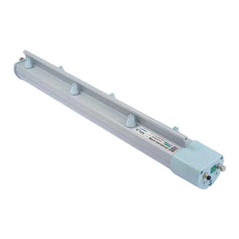
ITW Simco-Ion IQ Power Fantom User manual

IQ Power Fantom 5201292 Rev A
IQ Power™ Fantom
Wide Ionizing Blower
INSTALLATION AND OPERATING INSTRUCTIONS

i
IQ Power Fantom 5201292 Rev A
TABLE OF CONTENTS
1. SAFETY WARNINGS ........................................................................... 1
2. DESCRIPTION .................................................................................. 3
3. SPECIFICATIONS ............................................................................... 4
4. INSTALLATION .................................................................................. 5
Position and Mounting..........................................................................................................5
Electrical Connections..........................................................................................................5
Connection to User Interface................................................................................................6
Connection to IQ Power Control Station..............................................................................8
System Configuration...........................................................................................................9
Set-Up .................................................................................................................................13
5. OPERATION .................................................................................... 15
Indicator Lights...................................................................................................................15
Operation with IQ Power Control Station ..........................................................................16
6. MAINTENANCE .................................................................................17
Ionizing Emitter Points.......................................................................................................17
Air Intake Filter ..................................................................................................................17
Ionizer Module ...................................................................................................................17
Ion Balance .........................................................................................................................18
7. TROUBLESHOOTING ..........................................................................19
Operational Check ..............................................................................................................19
8. PARTS AND ACCESSORIES...................................................................21
9. WARRANTY AND SERVICE ...................................................................22

1
IQ Power Fantom 5201292 Rev A
1. SAFETY WARNINGS
PLEASE READ INSTRUCTIONS COMPLETELY BEFORE STARTING
INSTALLATION
ALL INSTALLATION AND TROUBLESHOOTING OPERATIONS MUST
BE PERFORMED BY QUALIFIED TECHNICAL PERSONNEL
This instruction manual uses symbols to identify dangerous situations as follows:
NOTE – Statements identified with NOTE indicate precautions necessary
to avoid potential equipment failure.
CAUTION – Statements identified with CAUTION indicate potential
safety hazards.
ATTENTION – Les déclarations identifiées avec ATTENTION indiquent
des dangers potentiels pour la sécurité.
WARNING – Statements identified with WARNING indicate potential
serious injury hazards.
AVERTISSEMENT – Les déclarations identifiées avec AVERTISSEMENT
indiquent un risque de blessures graves.
NOTE – This equipment must be correctly installed and properly
maintained. Adhere to the following notes for safe installation and operation:
1. Read instruction manual before installing or operating equipment.
2. Only qualified service personnel are to perform installation and repairs.
3. All equipment must be properly grounded, including the machine frame to
which the equipment is mounted.
4. Turn off input power to unit before connecting or disconnecting other
equipment.
5. Do not operate system in close proximity to flammable liquids.
6. Do not use standard Ethernet cables with IQ Power Systems.
NOTE – Do not attempt to operate at voltages other than those specified.
NOTE – Do not allow dust, dirt or debris to block or obstruct air flow inlets
or outlets.

2
IQ Power Fantom 5201292 Rev A
CAUTION – Electric Shock Hazard
Electrical installation and repairs must be performed by a skilled electrical
engineer according to the applicable national and local regulations. The
equipment must be properly grounded. Grounding is required to ensure
safe and proper operation and to prevent electrical shocks upon contact.
AVERTISSEMENT– Risque De Choc Électrique
L’installation et le service électrique doivent être effectuées par un électricien
qualifié conformément aux réglementations locales et nationales. Le
matériel doit être correctement mis à la terre. Mise à la terre est nécessaire
pour assurer un fonctionnement sûr et correct et pour éviter les chocs
électriques en cas de contact.
WARNING – Fire Hazard
Keep the unit dry. Do not operate the unit in flammable or explosive
environments.
AVERTISSEMENT – Risque d’incendie
Gardez l’appareil au sec. Ne pas utiliser l’appareil dans des environnements
inflammables ou explosifs.

3
IQ Power Fantom 5201292 Rev A
2. DESCRIPTION
Simco-Ion’s IQ Power Fantom Wide Blower is a highly reliable, extended-range
ionizing air blower designed for static elimination in many industrial applications.
Its high power fan covers a large area with balanced ionization for rapid static
neutralization. The Fantom is a self-contained unit that includes variable speed fan
control and closed-loop ion output and ion balance control. The built-in emitter
point cleaner provides manual, automatic, or remote cleaning to remove dust
buildup from the emitter points. This ensures full output of ionized air.
The Fantom features a user interface and indicators to continuously monitor
performance. It also supports connection to the IQ Power Control Station for
the ultimate in remote monitoring and control. Cables for interconnection with a
Control Station are available by calling Simco-Ion customer service (800) 203-3419
(refer to Section 8, Parts and Accessories).

4
IQ Power Fantom 5201292 Rev A
3. SPECIFICATIONS
Input Power
120 VAC, 50/60 Hz, 2A (fan speed high)
Fuse: 3A time delay ¼”x 1¼”
230 VAC, 50/60 Hz, 1A (fan speed high)
Fuse: 1.5A time delay ¼”x 1¼”
Operating Temperature 32-100°F [0-38°C]
Operating Humidity 70% RH max, no condensing (dewing) permissible
Air Volume* 600 cfm [18m3/min] max
Air Filter 11.3”x 25.8”[287 x 655 mm] polyurethane foam 10 ppi
Air Speed*
1600 fpm @ 1 ft. [8.1 m/s @ 0.3m]
1300 fpm @ 2’[6.6 m/s @ 0.6m]
1000 fpm @ 3’[5.1 m/s @ 0.9m]
900 fpm @ 4’[4.6 m/s 2 1.2m]
Fan speed high on centerline
Noise Level 64 dB @ 2’[0.6m], fan speed high
Discharge Time*
0.4 sec @ 1’[0.3m]
0.9 sec @ 2 ft [0.6m]
1.8 sec @ 3 ft [0.9m]
2.3 sec @ 4 ft [1.2m]
3.3 sec @ 5 ft [1.5m]
4.5 sec @ 6 ft [1.8m]
6.5 sec @ 8 ft [2.4m]
9.0 sec @ 10 ft [3.0m]
Fan speed high, 1000-100V (typ)
Mounting 3.94”x 20.28”[100 x 515 mm] mounting centers with 10-32 screws
Enclosure Steel, blue epoxy powder coated
Dimensions 12.75”L x 26”W x 8”H [324L x 660W x 204H mm]
Weight 31 lb [14 kg]
* Derate values ~20% when operating at 50 Hz.

5
IQ Power Fantom 5201292 Rev A
4. INSTALLATION
Position and Mounting
For maximum effectiveness, position the Fantom Wide Blower as close as possible to
the charged surface to be neutralized. Direct the air stream longitudinally, and in the
same direction as, the target material movement to maximize the time the charged
surface remains in the air stream. Ensure that the ionized air stream covers the entire
target surface, and that the material to be neutralized is not in direct contact with a
background surface (such as a roller or laying on a tabletop). For best results, the
material to be neutralized should be in free air.
The Fantom can be placed on any flat, level surface. It can also be secured using the
(4) large truss head screws on the bottom of the unit. The (4) large truss head screws
thread directly into the internal fan frame, providing a secure mounting.
Figure 1. Hole Pattern on Bottom of Unit (top view of unit)
Electrical Connections
Depending on the model, the Fantom Wide Blower requires 120 VAC or 230 VAC,
50/60 HZ. Connect line cord to a grounded receptacle. If an extension cord is used,
it must be a 3-wire type providing electrical ground to the unit.
NOTE – Do not attempt to operate at voltages other than those specified.

6
IQ Power Fantom 5201292 Rev A
CAUTION – Electric Shock Hazard
Electrical installation and repairs must be performed by a skilled electrical
engineer according to the applicable national and local regulations. The
equipment must be properly grounded. Grounding is required to ensure
safe and proper operation and to prevent electrical shocks upon contact.
AVERTISSEMENT– Risque De Choc Électrique
L’installation et le service électrique doivent être effectuées par un électricien
qualifié conformément aux réglementations locales et nationales. Le
matériel doit être correctement mis à la terre. Mise à la terre est nécessaire
pour assurer un fonctionnement sûr et correct et pour éviter les chocs
électriques en cas de contact.
Connection to User Interface
The User Interface provides connection to the alarm relay, the ability to remotely
activate the point cleaner, and the ability to remotely place the unit in standby. The
User Interface also provides a current limited source of +24 VDC for user signaling
purposes.
The connections for the User Interface are:
Terminal 1: +24 VDC Output (100 mA max.)
Terminal 2: Fault Relay N.C.
Terminal 3: Fault Relay Com.
Terminal 4: Fault Relay N.O.
Terminal 5:Clean Logic Input
Terminal 6: Standby Logic Input
Terminal 7: Ground
The connections for the User Interface is a 7-position pluggable header with screw
terminals. The connector accepts 16-26 AWG solid or stranded wire with a strip
length of ¼” [7 mm]. To install wires into the connector, push stripped wire
fully into the square hole on connector and tighten securely with a small flat-blade
screwdriver. The terminal block header is plugged into the User Interface, located
in a protective connector bay, on the side of the Fantom Wide Blower.
Outputs
The Fault Relay N.C. contact “makes” to indicate normal operation. The N.O.
contact “makes” to indicate an alarm. The N.O. contact also “makes” when power
is removed from the Fantom or the Fantom is turned off.

7
IQ Power Fantom 5201292 Rev A
The relay contacts are rated for a maximum of 1 amp at 24 volts, with a resistive
load.
Figure 2. User Interface Relay Output (Typical Indicator Schematic)
Figure 3. User Interface Relay Output (Typical Light Tree Schematic)
In a typical indicator or light tree application:
• The green light indicates the unit is operating correctly or in standby.
• The red light indicates the unit in fault or not powered.
Figure 4. User Interface Relay Output (Typical PLC Schematic)
In a typical PLC application:
• The PLC input will be held high during normal operation or in standby.
• The PLC input will be low on fault or if the unit is not powered.
Inputs
Two inputs are available at the User Interface. The automatic point cleaner may
be activated with a momentary application of voltage to terminal 5. The unit can
be placed and held in standby mode with the application of a voltage to terminal 6.

8
IQ Power Fantom 5201292 Rev A
Figure 5. User Interface Point Cleaner (Schematic)
A momentary application of +5 to +24 volts DC to terminal 5 (terminal 7 being the
return, 0 volts) will activate an automatic point cleaning cycle. If the blower fan is
operating (unit not in standby), the fan will be de-energized and allowed to come
to a stop (approximately 4 seconds). The automatic point cleaner will cycle three
times (approximately 6 seconds). If the unit was not in standby, the blower fan will
resume operation.
Figure 6. User Interface Standby (Schematic)
A continuous application of +5 to +24 volts DC to terminal 6 (terminal 7 being the
return, 0 volts) will place the unit in standby mode. In standby the blower fan and
ionization power supplies are de-energized. It takes approximately five seconds for
the unit to resume operation after the voltage is removed from terminal 6.
Connection to IQ Power Control Station
Two communication ports are available on the Fantom Wide Blower, COMM1 and
COMM2. These communication ports allow connection to an IQ Power Control
Station. Either port may be used for connection. COMM1 provides an M12
connector for round cable and COMM2 provides an RJ-45 connector for modular
cable. Cables of various lengths are available, see Section 8, Parts and Accessories.
NOTE – DO NOT USE standard Ethernet cables with IQ Power systems.
Avoid permanent equipment damage by using only Simco-Ion modular
cables. (Refer to Section 8, Parts and Accessories).

9
IQ Power Fantom 5201292 Rev A
Figure 7. IQ Power Crossover Modular Cable (black)
Connection with a Control Station allows two-way digital communication with the
Fantom Wide Blower. The Control Station is able to display a variety of operating
parameters and settings in the Fantom Wide Blower. If a Control Station is
connected to the Fantom, but the Fantom is not powered or turned off, the Control
Station will still be able to display the fixed settings in the Fantom Wide Blower.
NOTE – When a Fantom Wide Blower is connected to a Control Station,
the Fantom still requires connection to line voltage to operate.
System Configuration
The Fantom Wide Blower and related Control Station / IQ Easy Sensor Bar
can be configured in a variety of ways. When an ionizing blower is paired with
a static sensor bar, the pair is considered a single device by the Control Station.
The following figures each illustrate a fundamental configuration with specific
equipment. Fundamental configurations may be combined on a system to meet the
particular needs of the application.

10
IQ Power Fantom 5201292 Rev A
Figure 8. IQ Power Connections (Fantom to Control Station)

11
IQ Power Fantom 5201292 Rev A
Figure 9. IQ Power Connections (Fantom and IQ Easy Sensor to Control Station)

12
IQ Power Fantom 5201292 Rev A
Figure 10. IQ Power Connections (Fantom to IQ Easy Sensor and Control Station)

13
IQ Power Fantom 5201292 Rev A
Set-Up
If the Fantom Wide Blower is operating free standing (without connection to a
Control Station) set up is simply adjusting the air flow on target and adjusting the
blower fan speed if necessary.
When connected to a Control Station, a variety of information can be checked and
operating parameters may be set for the Fantom.
NOTE – If the Fantom is connected to a Control Station but the Fantom
power switch is off or power disconnected, the Control Station will display
a fault and basic information for the unit.
To edit or select an operating parameter, tap on pencil icon to right of parameter
description.
Device Name: A user editable name to identify the specific device (14 character).
Device Type: A fixed description for the device type (eg. Ionizing air blower)
Operation Mode: A user selectable operating mode for the ionizing air blower
(Fixed, Manual Narrow, Manual Wide, CLFB).
• Fixed - Ionization balance set to zero using the Ion Balance control on unit
(default factory setting).
• Manual Narrow - Allows fine manual control of the ion balance over a
narrow range using the IQ Power Control Station. This mode of operation
would only be selected where the material to be neutralized exhibited
consistent charging of one polarity. An electrostatic field meter would be
used to assure neutralization during set-up.
• Manual Wide - Allows coarse manual control of the ion balance over
a wide range using the IQ Power Control Station. This This mode of
operation would only be selected where the material to be neutralized
exhibited a challenging and consistent charging of one polarity. An
electrostatic field meter would be used during set-up.
• CLFB - Closed-loop Feedback, requires pairing with a downstream IQ Easy
Sensor Bar through the IQ Power Control Station. The sensor bar detects
any voltage imbalance on the material to be neutralized, then transmits this
information to the ionizing blower. The ionizing blower makes incremental
changes to the balance setting until material charges are minimized.
Ionization Output: The ionization level, in percent.
Ionization Current: The ionization level in terms of microamps for both positive
and negative ionization.

14
IQ Power Fantom 5201292 Rev A
Paired Sensor: The specific sensor bar to be used with this ionizing blower for
closed loop feedback control. The default is “none”; a specific sensor bar must be
selected to enable closed loop feedback control. The specific sensor bar is selected by
choosing its “device name”. The sensor bar MUST be located where it will monitor
the material being neutralized.
Balance: A ratio of input power supplied to the high voltage power supplies that
related to ion balance. In Balanced and CLFB modes this is a display only and non-
editable. The Balance number may only be user adjusted in the Manual modes.
Data Logging: An on/off setting to enable data logging for this device. The factory
default is off.
Firmware Version: The firmware revision in the ionizing blower.

15
IQ Power Fantom 5201292 Rev A
5. OPERATION
Turn unit on with main power switch, located adjacent to the line cord. After the
Fantom goes through an automatic point cleaning cycle, it will begin operating. The
fan speed may be adjusted with the fan speed adjustment knob. Use the highest
airspeed the application allows. This insures quick discharge times and maximum
coverage.
Indicator Lights
Figure 11. Fantom Indicator Lights and Adjustments
Two sets of indicator lights are on the Fantom Wide Blower. One set is visible
through the unit face label. The second set is located in the connector bay, above
the User Interface. This set is visible from the side of the unit.
Power
• A steady green Power light indicates the unit is powered and active.
• A blinking green light indicates the unit is in standby.
• A rapidly flashing green light indicates the unit has received a command
from the Control Station. The rapid flashing only lasts for several seconds.
Warning
• A steady yellow Warning light indicates the internal monitoring and control
circuits are approaching the limits for normal operation (the unit is still
in closed-loop control). The unit may need to be cleaned or otherwise
serviced.

16
IQ Power Fantom 5201292 Rev A
Fault
• A steady red Fault indicates the internal monitoring and control circuits
have exceeded limits for normal operation (the unit is no longer in closed-
loop control).
• A steady red Fault light may also indicate a failure of a high voltage power
supply or control circuitry.
• A steady red Fault light is also used to indicate the Fantom is connected to
a Control Station and AC line voltage is not applied or the Fantom power
switch is off.
Operation with IQ Power Control Station
Operation of the Fantom Wide Blower can be controlled through the IQ Power
Control Station. In operation, a device icon appears on the Control Station Home
Page. Tapping on the device icon opens a Summary page containing information
about the Fantom ionizing blower and sensor bar (if paired). More detailed
information and user editable parameters are available through device tabs on the
Control Station screen. For more information on these details see Set Up section
in this document.
NOTE – When a Fantom Wide Blower is connected to a Control Station,
the Fantom still requires connection to a line voltage to operate.

17
IQ Power Fantom 5201292 Rev A
6. MAINTENANCE
Ionizing Emitter Points
1. Dust or dirt on the ionization points will reduce effectiveness of the blower.
Ionization points must be cleaned periodically to prevent deposits from
accumulating.
2. Simply turn OFF and back ON. The automatic point cleaner will cycle three
times to clean the ionizing points. If the automatic point cleaner should
become inoperative, there is a Point Cleaner button adjacent to the ionized air
outlet. Push the button several times to clean the ion emitter points.
3. Frequency of cleaning should be at least once monthly, or as determined by
inspections based on operating conditions.
Air Intake Filter
1. Filter cleaning or replacement frequency depends upon the cleanliness of the
operating environment. Inspect filters weekly, clean or replace as required.
2. Turn the unit OFF and remove air filter from intake.
3. The air filter is open cell polyurethane. It may be cleaned with mild soap and
water. Rinse thoroughly and allow to dry before reinstalling.
4. To install air filter, place over intake grille. Tuck edges of air filter in recess
around perimeter of intake grille.
Ionizer Module
CAUTION – Risk of Injury
Turn off and disconnect unit from line voltage before removing ionizer
module. Use care handling ionizer module, puncture hazard, sharp pins
are present.
MISE EN GARDE – Risque de blessure
Éteindre et débrancher l’unité de la tension secteur avant de retirer le
module ioniseur. Manipuler le module ioniseur avec précaution, risque de
piqûre, broches pointues présentes.
1. Turn unit OFF.
2. Loosen (4) screws located at corners of ionized air outlet. The screws are captive
and will remain with ionizing module.
3. Remove ionizing module. The side opposite the point cleaner button contains
electrical connectors. It may be necessary to grasp this side and rock the
ionizing module gently to disconnect the connectors.

18
IQ Power Fantom 5201292 Rev A
4. Handle the ionizing module with care. The ion emitters are sharp pins that
present a puncture hazard.
5. Dirt and debris may be brushed or vacuumed from the ionizing module, or the
ionizing module may be replaced.
6. To install the ionizing module, line the Point Cleaner hole with the point
cleaner button and insert module into unit.
7. Secure the ionizer module with the (4) screws at the corners of ionized air outlet.
8. Press Point Cleaner button and make sure it returns freely to check for proper
operation of the point cleaner.
Ion Balance
1. A closed-loop electronic balancing circuit in the blower controls the output
ration of negative to positive ions. The circuit is preset at the factory and
normally requires no further adjustment.
2. Balance may be evaluated using a charged plate monitor such as the Simco-Ion
CPM. The plate should be placed at the typical operating distance for testing
and adjustment. Static charges in the vicinity of measurement will affect
reading, remove or neutralize static charges in the vicinity before taking ion
balance measurements.
3. The balance adjustment potentiometer is accessible through a small opening on
the face label of the Fantom. Using a flat-blade screwdriver, carefully adjust the
potentiometer until the charged plate monitor indicates “zero”.
Table of contents
Other ITW Air Ionizer manuals
Popular Air Ionizer manuals by other brands

Vessel
Vessel Stat-Clean C-90 instruction manual

Desco EMIT
Desco EMIT C/E Series owner's manual

GPS
GPS GPS-FC24-AC Installation, operation & maintenance manual

ESD SYSTEMS
ESD SYSTEMS Eliminator Plus Installation, operation and maintenance

GPS
GPS iRIB-18 Start-Up Checklist

Prime Water
Prime Water Prime 501S user manual