6
Chargemaster Pinner 5200710 Rev. H
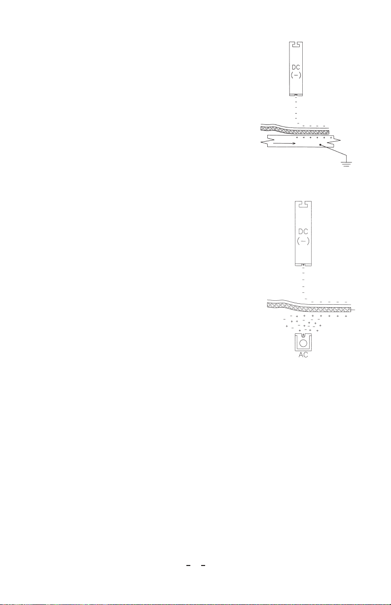
Option 3: Two Charging Bars
In Figure 4, one charging bar faces another
of opposite polarity in an application where
decorative sheets are pinned to both sides of
heavy particle board prior to laminating. As
the materials move between the charging bars,
the opposite polarity ions created by each bar
are driven toward each other by an electric field
formed between them. The decorative sheets
block ion travel through the field and become
electrostatically charged, resulting in adhesion
between the two sheets and the particleboard.
With this arrangement, the voltage differential
between the charging bars can be substantial. The
sizeable voltages cause higher levels of charge to be
deposited on the decorative sheets, which results
in the highest level of electrostatic adhesion. This
method of charging materials is generally used
in the most difficult pinning applications. Dual
polarity BP-Series power supplies are designed for
applications like this.
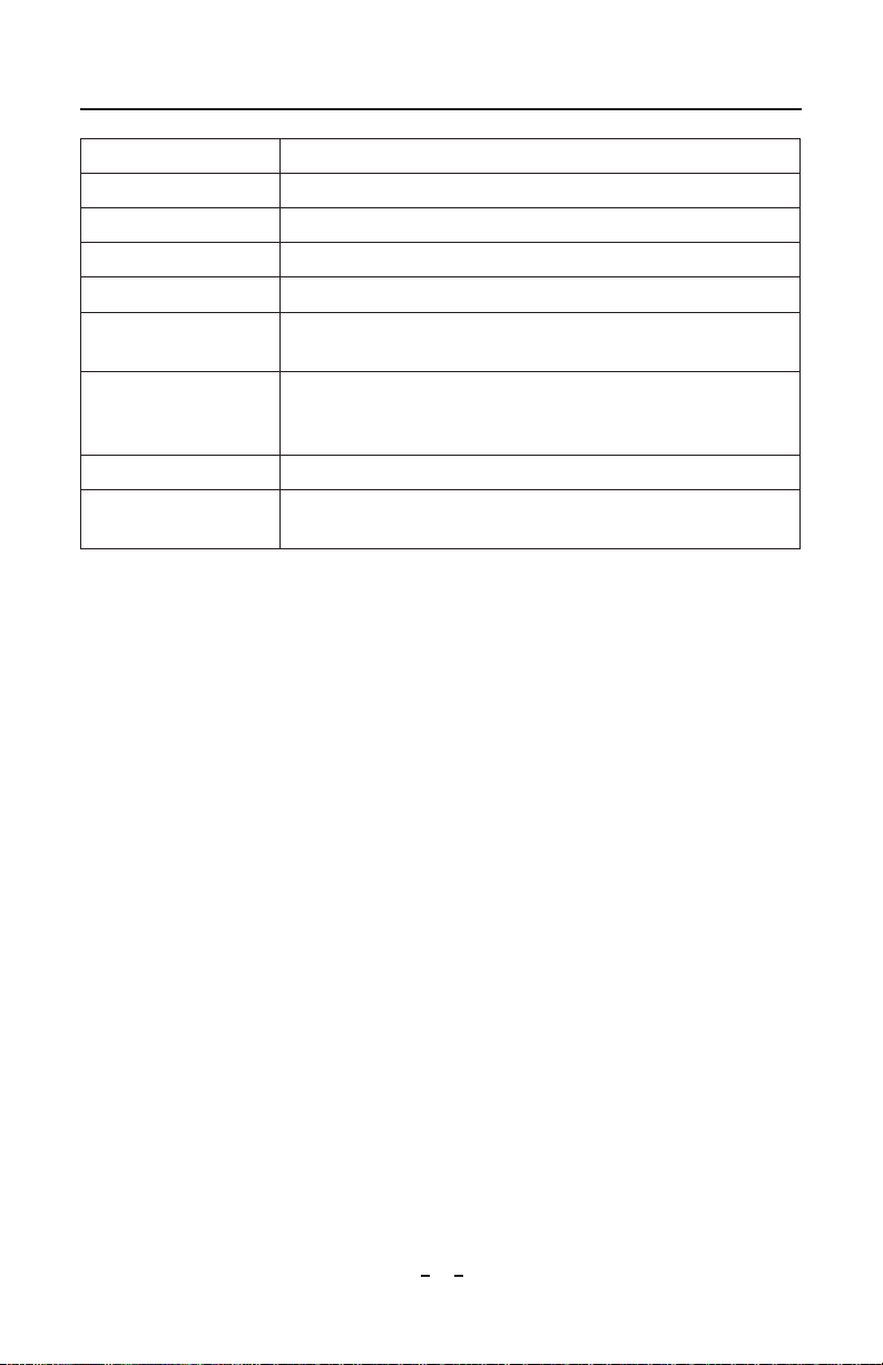
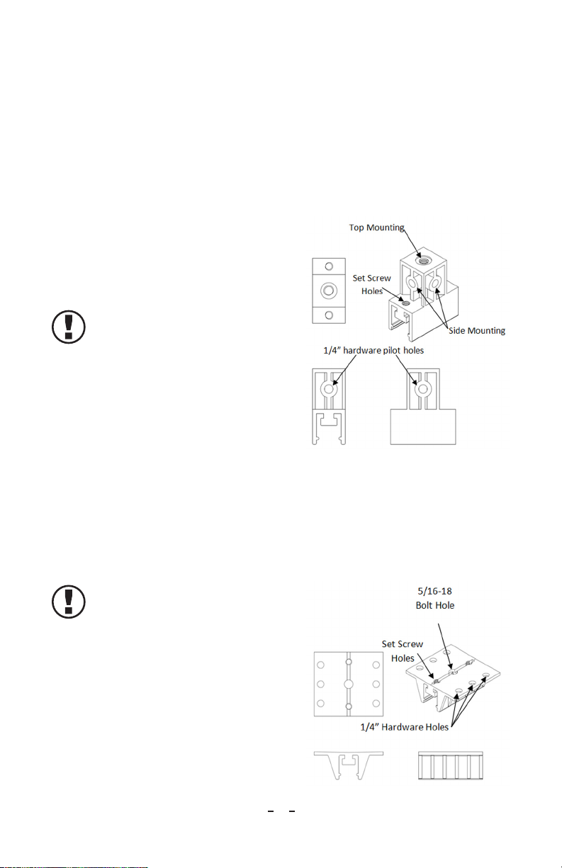
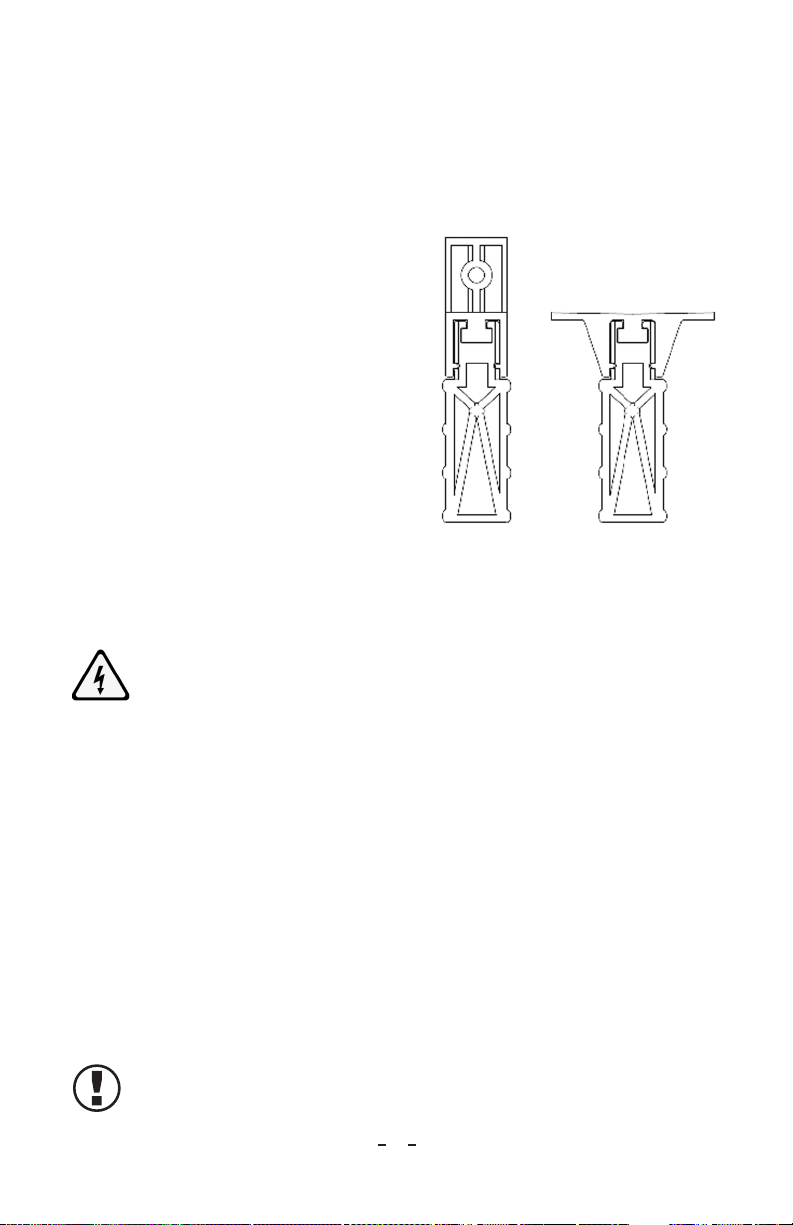
Mounting Charging Bars
CAUTION – FIRE HAZARD
Do not install or operate equipment in close proximity to any flammable
solvents or flammable materials.
CAUTION –ELECTRICAL SHOCK HAZARD
Only qualified service personnel are to perform installation tasks.
CAUTION –ELECTRICAL SHOCK HAZARD
It is essential that the machine frame, and all metal parts in the vicinity,
be grounded either through well-grounded electrical conduit or by heavy
copper wire connecting the frame to a water pipe.
NOTE – Pinner Bars are shipped from the factory with a 50 kV connector
installed on the cable. A 30 kV connector is also supplied and must be
installed for use on all Simco-Ion Chargemaster power supplies with ratings
of 30 kV and lower.
Determine the best location for the for guidance.
Figure 4