ITW ACME DTPN-250 Instruction Manual

DTPN-250
AIR POWERED TENSIONER
Part No. 306240
For Parts & Service 1-877-862-6699
WWW.TRADITIONALTOOL.COM

READ THESE INSTRUCTIONS CAREFULLY.
FAILURE TO FOLLOW THESE INSTRUCTIONS CAN RESULT IN SEVERE PERSONAL INJURY.
GENERAL SAFETY CONSIDERATIONS
1. STRAP BREAKAGE HAZARD.
Improper operation of the tool or sharp corners on the load can result in strap breakage
during tensioning, which could result in the following:
!
!!
!A sudden loss of balance causing you to fall.
!
!!
!Both tool and strap flying violently towards your face.
Failure to place the strap properly around the load or an unstable or shifted load could result
in a sudden loss of strap tension during tensioning. This could result in a sudden loss of
balance causing you to fall.
Read the tool's operating instructions. If the load corners are sharp use edge protectors.
Place the strap correctly around a properly positioned load.
!
!!
!Positioning yourself in-line with the strap, during tensioning and sealing, can result in
severe personal injury from flying strap or tool. When tensioning or sealing, position
yourself to one side of the strap and keep all bystanders away.
!
!!
!Using strap not recommended for this tensioner can result in strap breakage during
tensioning. Use the correct Acme products for your application.
2. TRAINING.
This tool must not be used by persons not properly trained in its use. Be certain that you
receive proper training from your employer. If you have any questions contact your Acme
Representative.
3. EYE INJURY HAZARD.
Failure to wear safety glasses with side shields can result in severe eye injury or
blindness. Always wear safety glasses with side shields which conform to ANSI
Standard Z87.1 or EN 166.
4. FALL HAZARD.
Maintaining improper footing and/or balance when operating the tool can cause you to fall.
Do not use the tool when you are in an awkward position.
5. CUT HAZARD.
Handling strap or sharp parts could result in cut hands or fingers. Wear
protective gloves.
For Parts & Service 1-877-862-6699
WWW.TRADITIONALTOOL.COM

6. TOOL CARE, MAINTENANCE & PARTS REPLACEMENT
!
!
!
!Take good care of the tool. Inspect and clean it daily, lubricate it weekly and adjust
when necessary. Replace any worn or broken parts.
!
!!
!ALWAYS disconnect the pneumatic connection to the tool when performing part
removal and/or replacement procedures. NEVER connect a pneumatic source to a
disassembled tool unless otherwise specified.
7. WORK AREA.
Keep work areas uncluttered and well lighted.
Several combinations of strap, seals and tools can be used with this tensioner. Use the correct
Acme products for your application. If you need help contact your Acme Representative.
SAFETY PROCEDURES FOR TOOL OPERATION
Before using this tool, read its Operation and Safety instructions.
!
!!
!Do not exceed the operating air pressures stated elsewhere in the manual.
!
!!
!Use a Acme approved filter-regulator-lubricator unit.
!
!!
!Never operate a pneumatic tool with a bottled air or gas source.
!
!!
!For tension adjustments, follow instructions in this manual. For all other adjustments,
repairs or cleaning of the tool, disconnect air supply.
!
!!
!Properly crimp or notch the seal(s).
!
!!
!Tuck strap end back into the dispenser when not in use.
CUTTING TENSIONED STRAP
Use only cutters designed for cutting strap; never use claw hammers, crowbars, chisels, axes or
similar tools. Such tools will cause the strap to fly apart with hazardous force. Before using any
Acme product, read its Operation and Safety Manual.
For Parts & Service 1-877-862-6699
WWW.TRADITIONALTOOL.COM

TABLE OF CONTENTS
General Safety Instructions 2
Specifications 4
Pneumatic Information 5
Tool Installation 7
Tool Operation 8
Parts List & Exploded View 10
Repair Instructions 14
Maintenance 15
Maximum operating pressure
is 90 psig (6.2 bar).
DTPN-250 TENSIONER
SPECIFICATIONS
MODEL
(Part No.)
STRAP
TYPE WIDTH THICKNESS
DTPN-250
(306240)
Steel 2" .044" to .050"
For Parts & Service 1-877-862-6699
WWW.TRADITIONALTOOL.COM

PNEUMATIC INFORMATION
AIR SUPPLY INSTALLATION
If compressor has a good dryer unit, use black pickled pipe. When a dryer unit is not installed,
use galvanized or copper pipe. To perform reliably, a pneumatic tool requires a continuous
source of clean, water-free air at adequate pressure.
Never operate this tool using a bottled air or gas source.
Bottled air/gas sources do not provide consistent operating pressure
A filter-regulator-lubricator
(FRL) unit must be installed as
close to the air tool as possible,
preferably within 10 feet. It
should be placed in a
convenient location where it
can easily be drained, adjusted,
and filled with oil. The air hose
must have at least a 3/8" I.D. A
quick disconnect socket fitting
is installed on the stress spring
end of the hose for convenient
hookup to the air tool.
Filter-Regulator-Lubricator Unit
(Acme Part No. 008559 or 173111)
FRL Mounting Bracket
(Acme Part No. 071982)
Air Hose, 3/8" ID, 1/4" Fittings
(Acme Part No. 008558)
Reducer Bushing, 3/8" to 1/4"
(Acme Part No. 008478)
Quick Disconnect, 1/4" Fitting
(Acme Part No. 020706)
Filter and lubricator bowls are made of polycarbonate material. Do not install where bowls may
be exposed to materials incompatible with polycarbonate. Certain oils, solvents, and chemicals
or their fumes can weaken these bowls and possibly cause them to burst. Clean only with warm
water. A cut-off valve placed ahead of the filter will be useful when cleaning the filter or
replenishing the lubricator.
For Parts & Service 1-877-862-6699
WWW.TRADITIONALTOOL.COM

PNEUMATIC INFORMATION, Continued
MOISTURE
Moisture is always present in air lines due to condensation within the lines as the air cools.
Steps must be taken to remove this moisture and to keep it from the air tool. This is because
water tends to wash away lubricants and cause corrosion, sticking and failure of internal parts.
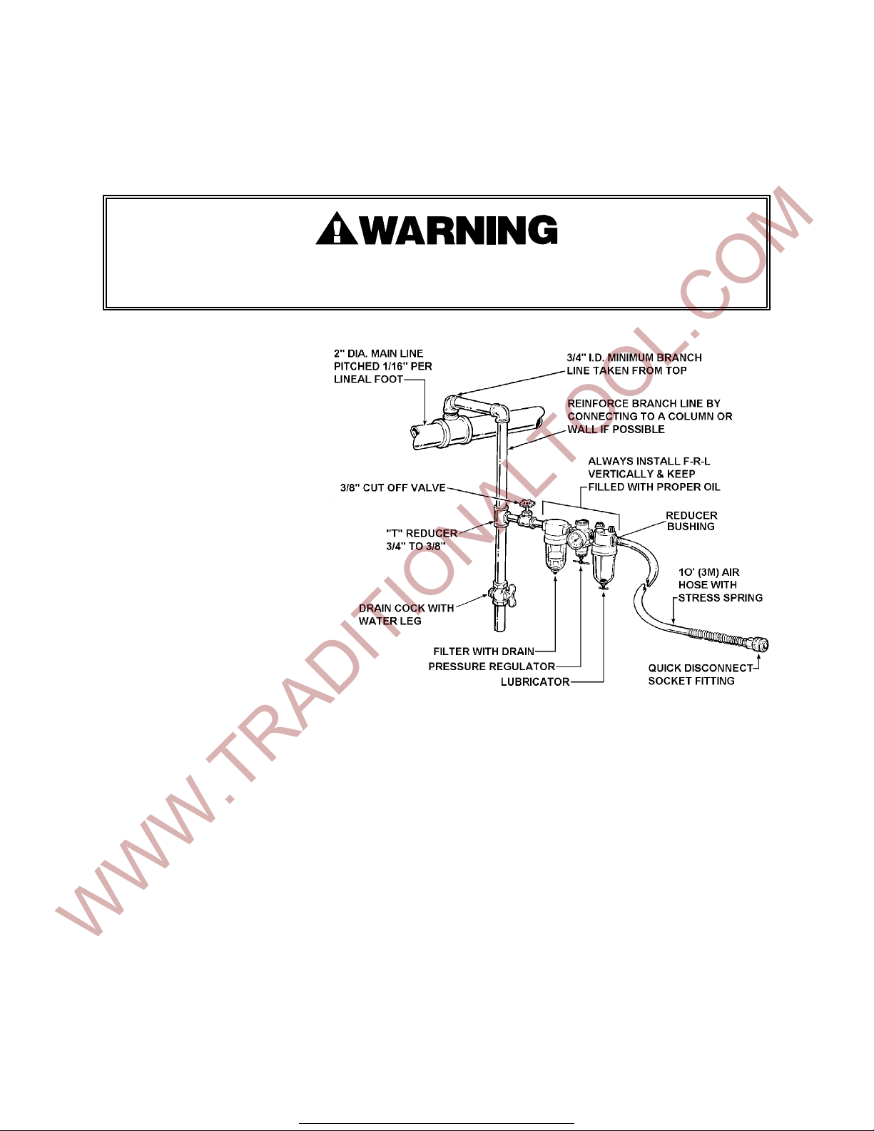
The main line should be pitched so the far end terminates in a water leg. Branch lines are taken
from the top of the main, never off the bottom. Every branch should have a water leg at its
lowest point, with a drain cock which is drained daily.
If these precautions are taken and water is still present, an after cooler and a moisture separator
are required between the compressor and the air receiver tank. A large air line separator can be
installed in the air tool line, but precautions must be taken to insure that it will be drained daily,
before the air tool is operated.
Water in air lines is a constant threat to the proper operation of air tools. Even near freezing
operating conditions, a good refrigerant type dryer is essential. A good dryer will remove 95%
or more of water right at the compressor. The remaining moisture is removed at the water leg in
the piping system or in the filter.
LUBRICATION
The air tool must be properly lubricated. This is achieved by keeping the air line lubricator filled
with oil and correctly adjusted. Without proper lubrication, the tool will become sticky and will
be difficult to release from the strap.
Install the lubricator as close to the air tool as possible. The arrow on the lubricator's top
surface must point in the direction of air flow.
For proper operation, oil must drop through the lubricator sight glass at a rate of 4 to 10 drops
per minute. This rate is checked while the air tool is running free. Only 20% of this oil is actually
delivered to the tool. The remaining oil drops back into the oil reservoir. The unit is factory set
and should require no adjustment. If an adjustment is required, the adjusting screw on top of
the lubricator may be turned as marked to reduce or increase the flow of oil.
The correct grade of oil must be used in the lubricator; too heavy an oil will not provide sufficient
lubrication and will cause sticking and sluggish operation of the air tool.
Recommended oils are any good grade of rust and oxidation inhibiting oil with a viscosity of 80-
120 S.U.S. at 100 degrees Fahrenheit. (0.15 to 0.25 cm2/sec. at 38 degrees Celsius), such as:
Non Fluid Oil Co., grade #LS-1236
If necessary, use SAE #5 or SAE #10 non-detergent, cut 1 to 1 with kerosene.
NOTE: Some oils contain anti-wear additives which may disable the tool. Be certain to use
recommended oil.
Several drops of lubricator oil added to the inlet of the air line each day will help insure good
operation. A noticeable reduction of performance can usually be corrected by squirting a few
drops of oil into the air line.
For Parts & Service 1-877-862-6699
WWW.TRADITIONALTOOL.COM

COLD WEATHER OPERATION
If a tool does not operate satisfactorily in freezing temperatures, certain steps can correct the
problem. The following steps can be taken to improve cold weather operation of the tool:
a. An air line dryer adjacent to the compressor.
b. Use lubricant recommended by Acme. Acme has tested the use of anti-freezes, none work
well in air tools; the tool will gum up when anti-freezes are introduced and will not function
properly. The best lubricant for freezing weather is the 1 to 1 oil and kerosene combination.
c. If possible, run the air supply line to a indoor located Filter-Regulator-Lubricator or relocate
the F-L-R to a warmer operating area.
AIR PRESSURE VS. APPROXIMATE STRAP TENSION
Air Line Pressure (psig) Strap Tension (lbs.)
50 psig (345 kPa) 4,000 lb. (17800 N)
60 psig (415 kPa) 5,000 lb. (22200 N)
70 psig (485 kPa) 6,000 lb. (26700 N)
80 psig (550 kPa) 7,000 lb. (31100 N)
90 psig (620 kPa) 8,000 lb. (35600 N)
Recommended Recommended air
strap sizes pressure (psig)
2" x .044 50 to 90 psig
2" x .050 50 to 90 psig
Strap breakage hazard. Strap can break during tensioning if inlet air
pressure to the tool exceeds 90 psig. Strap breakage can result in
severe personal injury. Maximum operating pressure is 90 psig.
TOOL INSTALLATION
To operate effectively, your tool must be installed properly. This installation includes proper
suspension of the tool over the package to be strapped, correct placement of a strapping
dispenser to provide a continuous easy supply of strap for the application, and a satisfactory air
supply with air line pressures being maintained within the specified range.
For Parts & Service 1-877-862-6699
WWW.TRADITIONALTOOL.COM

TOOL OPERATION
Wear safety glasses which conform to
ANSI standard Z87.1 or EN 166. Stand to
one side of the strap while tensioning.
Make sure all bystanders are clear before
proceeding.
1. Raise the gripper wheel by pressing
down on the pawl handle. Insert the
bottom strap and release the pawl
handle. Allow one foot of strap to extend
beyond the front of the tool.
2. Thread seals properly on to upper strap.
3. Thread strap in to the windlass and
under the strap pin. Strap should extend
4" - 8" beyond the windlass.
NOTE: Make sure straps are fully seated
against the base.
4. Pull out slack, turn valve clockwise to
rotate windlass about 1/2 turn to secure
strap in the windlass.
5. Thread seals properly on to bottom
strap.
For Parts & Service 1-877-862-6699
WWW.TRADITIONALTOOL.COM

6. While standing to one side of the strap
line, rotate the valve collar clockwise to
tension strap allowing motor to stall out
at desired tension.
If for some reason the gripper will not
energize, do not try to energize using the
pawl handle, as this will result in
disengagement of the ratchet wheel.
Apply light machine oil to the pivot pin
(5), until the lever moves freely.
7. At the end of the tensioning cycle, use
sealing tool to notch or crimp seals.
8. After sealing the strap, rotate the valve
collar counterclockwise to unwind the
windlass. Note tab end of strap in
windlass. When this becomes loose, the
tool will be easily removed. The valve
collar is spring loaded to the reverse
direction so that when released, the
valve will return to neutral.
Lift the pawl handle thereby disengaging
the ratchet wheel. Then press down on
the pawl handle and rotate the tool off
the strap in a counterclockwise
direction.
For Parts & Service 1-877-862-6699
WWW.TRADITIONALTOOL.COM

PARTS LIST, TOOL
KEY QTY PART # DESCRIPTION
1 1 160479 Bearing shim
2 1 002481 Name plate
3 3 005211 Flexlock nut 3/16-18
4 2 005214 Roll pin 1/4 dia. x 3/4
5 2 004939 Drive screw
6 1 008154 FHSCS, 3/16-18 x 1
7 3 008531 Stud
8 6 008731 SHCS, 10-24 x 3/4
9 1 008774 Key, Woodruff #3
10 3 008815A Idler gear assembly
11 1 008825 Spacer
121 008826 Key
13 1 008827 Idler plate
14 1 008829 Ring gear
15 1 008148 Roll pin, 1/8 x 7/16
16 1 008854 Ball bearing 7304W
17 1 023053 Base
18 1 023054 Gear housing
19 1 023055A Motor
20 1 023056 Spiriod gear
21 1 023057 Spiriod worm
22 1 023058 Pawl handle
23 1 023059 Windlass
24 1 023063 Gripper
25 1 023064 Front link
26 1 023065 Rear link
27 1 023066 Ratchet gear
28 1 023067 Gripper shaft
29 1 023068 Support pin
30 1 023069 Center link
31 1 023071 Spacer
32 1 023072 Key, Woodruff #21
33 1 023073 Gripper spring
34 1 023074 Strap pin
35 1 023075 Pawl spring
36 1 023076 Tool handle
37 1 023077 Wear pad
38 2 023080 Roll pin 3/16 x 7/8
39 1 023668 Plastic grip
40 1 008645 Bearing,Fafnir 205KDD
41 1 023742 Bearing,Fafnir 210PP
42 1 023743 Bearing,Torr. M-871
43 1 023744 Oil Seal
44 2 023745 SHCS,5/16-18x2-3/4
45 1 023746 FHSCS,5/16-18x2-1/4
50 1 023272 Handel protector
51 1 003132 Danger Sign
NOTES
1. Use large quick disconnect fittings: Socket P/N 020706, Plug P/N 020704
2. Assemble wear pad with "B" side down.
!
!!
!When ordering parts please show tool model, part number and name.
!
!!
!Standard hardware parts may be obtained from your local hardware supplier.
!
!!
!Recommended spare parts are underlined and should be stocked.
For Parts & Service 1-877-862-6699
WWW.TRADITIONALTOOL.COM

For Parts & Service 1-877-862-6699
WWW.TRADITIONALTOOL.COM

PARTS LIST, AIR MOTOR 306387
KEY QTY. PART NO. DESCRIPTION
1 1 422221 Ball bearing
21422222 End plate
3 1 422223 Pin
4 1 422224 Cylinder
5 1 422701 Rotor
6 1 422702 Pin
7 1 422227 Ball bearing
8 1 422703 End plate
9 5 422229 Vane
10 1 422704 Motor casing
11 1 422232 Flow washer
12 1 422233 Axle
13 1 422234 Valve
14 1 422235 Spring
15 1 422236 O-ring
16 1 422237 O-ring
17 1 422238 Adapter
18 1 422239 Circlip
19 1 422240 Sleeve
20 1 422241 Bearing needle
21 1 422242 Throttle ring
22 1 422243 Bearing needle
23 1 422244 Pin
24 1 422705 Silencer
25 1 422246 Circlip
26 1 422247 Silencer
27 1 422248 Cover
28 1 422249 Silencer
29 1 422250 O-ring
30 1 422251 Cup spring
31 1 422752 Washer
32 1 422753 Lubricating nipple
33 1 422754 Circlip
34 2 422756 Ball bearing
35 1 422757 Gear rim
36 1 422706 Flange
37 2 422707 Circlip
38 1 422708 Planet shaft
39 2 422266 Axle pin
40 2 422267 Needle bearing
41 2 422709 Gear wheel
!
!!
!When ordering parts please show tool model, part number and name.
!
!!
!Standard hardware parts may be obtained from your local hardware supplier.
TROUBLESHOOTING TIP - If the air motor does not run or runs sluggishly:
1. Observe the air pressure gauge and adjust the regulator if necessary.
2. Inspect the filter screen in the air motor inlet. Clean the filter if necessary.
3. Inject one (1) teaspoon of lubricator oil into the air motor inlet. Let the air motor run free.
If motor speed increases, check lubricator to see that it is filled and properly adjusted.
For Parts & Service 1-877-862-6699
WWW.TRADITIONALTOOL.COM

For Parts & Service 1-877-862-6699
WWW.TRADITIONALTOOL.COM

REPAIR INSTRUCTIONS
Refer to pages 10 & 11 of this manual for additional part information and location.
GRIPPER AND WEAR PAD DISASSEMBLY
Remove the following parts:
•Front roll pin (38)
•
• Front link (25)
• Gripper (24)
• Roll pin (15)
• Wear pad assembly (37)
Clean, inspect and replace worn and/or broken parts. Clean gripper with wire brush.
NOTE: Gripper can be re-used by rotating it to a new position on the hexagonal gripper shaft.
GRIPPER AND WEAR PAD REASSEMBLY
Clean, inspect and replace worn and/or broken parts before reassembly. Lubricate all moving
parts with Mo-Lith #2 grease, or equivalent, before reassembly. Install the following parts as
described:
• Wear pad assembly (37)
• Roll pin (15)
• Gripper (24) - Rotate gripper so that unworn teeth contact the strap.
• Front link (25) - Grasp the support pin (29) with pliers at rear link (26) and rotate to align
hole.
• Front roll pin (38) - Drive in roll pin. Check that pawl handle is spring loaded in both
directions.
For Parts & Service 1-877-862-6699
WWW.TRADITIONALTOOL.COM

TOOL MAINTENANCE
GENERAL - The most common reason for poor tool performance and incorrectly formed straps
joints is improper tool maintenance. The easiest way to determine if a tool is performing
correctly is by inspecting the strap joint. Having a tool maintenance program is a simple task
which consists of three parts. First, a quick daily inspection of the tool for any worn or broken
parts. Secondly, keep each tool on a schedule of service intervals for cleaning and lubrication.
Third, when problems do occur, use the troubleshooting guide to properly determine and fix
problems before they lead to more serious tool conditions. Each of these three tasks have been
outlined for this particular tool, read and understand all information for improving the life and
performance of the tool.
SPECIFIC:
At the beginning of the day:
1. Drain filter and moisture traps in the air line.
2. Check lubricator oil level and refill if necessary.
3. Observe air pressure gauge to determine that the regulator is adjusted to the correct
pressure.
4. Use a wire brush to clean the gripper.
At the end of the day:
1. Disconnect the air hose from the tool.
2. Rotate the twist-valve clockwise and squirt one (1) teaspoon of lubricating oil into the air
motor.
3. Return the twist-valve to neutral and reconnect the air hose.
4. Rotate the twist-valve clockwise and allow the air motor to run free for one minute. Wipe
excess oil from the exhaust with a cloth.
TOOL INSPECTION - Visually inspect the exterior of the tool on a daily basis. Decreased tool life
can be prevented by early detection of broken parts. Replace all broken parts with new parts.
Review the Parts Removal, Replacement & Adjustments portion of this manual for information
and details.
SERVICE INTERVALS - Tool component wear is affected by the environment and strap tension
that the tool is subjected to. In the worst case, heavy gauge wide strapping. All critical moving
components of the tool should be inspected at particular intervals, some more often than others.
Broken parts can lead to additional component wear and produce lower strap tension.
If there is any question that joint formation is not as shown or is
suspect, it is important that you contact your tool representative immediately.
TOOL LUBRICATION - Acme tools use a variety of greases and oils, all of which can be ordered
through Acme. When ordering indicate tool model, part number and name. The gear housing of
this tool should be packed 1/3 full with non-fluid oil #K55. Pack any open bearings before
assembly.
THREAD SEALANTS - Acme tools are assembled using a variety of thread sealants, all of which
can be ordered through Acme using the appropriate description shown below.
!
!!
!Loctite #222
!
!!
!Loctite #242
!
!!
!Loctite #609
For Parts & Service 1-877-862-6699
WWW.TRADITIONALTOOL.COM