ITW Simco-Ion EA-5J User manual

INST-09052212
Simco-Ion Handy Charge Plate Monitor
Model EA-5J
INSTRUCTIONS
Installation/Operation/Maintenance
CAUTION
It is important that these instructions be read and understood
before attempting to install or operate the equipment. Failure to
do so could result in serious personal injury and/or damage to
the equipment. At the end of this manual, a written warranty is
provided. This should be preserved carefully.

Notes to users
WARNING
This equipment is not constructed for classified hazardous environment. It cannot be used()
where it will be exposed to ignitable or corrosive materials and gases.
CAUTION
This equipment is intended for use in electrostatic processes that are free from water, oil,
solvent and other conductive contaminants. Exposure to such contaminantswillcausefailure
of the electrical insulation system in the product. Special care should be taken to ensure that
there is no dew formation. This equipment should be stored or used in a place less than
60 %RH.
Do not insert any object in the opening for the sensor located at the measuring side of the
instrument; no foreign substance should ever enter into the sensor opening.
This equipment should not be operated in an ambient with corrosive fumes of acid/alkali or
corrosive gases such as chlorine.
When not in use, please switch off the instrument.
This equipment must have proper grounding for accurate measurement.
This equipment is likely to be damaged by a fall. In such an event, it should be carefully
examined and any necessary repairs be made by an authorized technician. This is an
electronic instrument and contains sensor that is sensitive to mechanical vibrations and shock.
As it also contains a microcomputer chip and electronic circuitry it should not be used in an
environment where there is a lot of electromagnetic noise.
Suspend measurement when the voltage reading is outside the measuring range. If the value
is exceeds the range there is a possibility of damaging the sensor.
Do not exert any pressure on the LCD display from the top.
Clean the sensor plate and supported insulators for accurate measurement.
The equipment was assembled and inspected at Simco Japan, Inc. Do not attempt to
disassemble or modify its construction. If you are not clear about its operation and
maintenance, call Simco Japan's authorized agent in your area.
-page1-

Thank you for buying Simco-Ion products. This equipment will meet your expectations and
provide safe operation when it is properly installed and maintained.
Receipt of equipment
Please carefully remove the equipment from the carton and inspect. Note anydamagethat
might have occurred during shipment. Empty the carton to ensure that small parts are not
discarded.
If any damage has occurred during shipment, the local carrier should be notified at once. A
report should be forwarded to SIMCO JAPAN, INC. The address and other relevant
information are written on the back cover page.
Packing articles and accessories
1 EA-5J ................................................................................... 1 pc.() Controller
2 CPM-LPS .......................................................................... 1 pc.() Plate sensor
3 Grounding cord, 2 m long .................................................................. 1 pc.()
4 Instructions / Warranty ....................................................................... 1 pc.()
Option:
1 USB Cable ........................................................................................... 1 pc.()
2 USB-AC ADAPTER ........................................................................... 1 pc.()
3 C ......................................................................................... 1 pc.() arrying case
4 Analog output cable ............................................................................ 1 pc.()
Please check if any part is missing or does not
have satisfactory finish. Contact us or our agents
immediately in the event of such occurrence.
-page2-

Contents
Notes to Users .........................................................................................page 1
Receipt of equipment...............................................................................page 2
Packing articles and accessories..............................................................page 2
Contents....................................................................................................page 3
Section 1. General description.................................................................page 4
Section 2. Features...................................................................................page 5
Section 3. Specification ..........................................................................page 6
Section 4. External view..........................................................................page 10
Section 5. Setup........................................................................................page 12
Section 6. Manual mode measurement....................................................page 20
Section 7. Auto mode measurement........................................................page 26
Section 8. Saved data copy......................................................................page 30
Section 9. Tables of functions..................................................................page 34
Section 10 Troubleshooting......................................................................page 35
Section 11 Dimensional drawings............................................................page 36
Simco-Ion EQUIPMENT REPAIR WARRANTY......................................enclosed
Explanation of Symbols:
WARNING
ATTENTION / CAUTION
ELECTRIC SHOCK HAZARD
-page3-

Section 1. General description
Simco-Ion Model EA-5J Charge Plate Monitor CPM is a compact instrument usedfor()
measuring the ionizer's performance. It is small, portable, handy and easytouse.
It was designed to provide quantitative, accurate measurements for a variety of air
ionization tests. It can be easily used for Discharge time Decay time and Ion Balance()
measurements for the ionizers. It is the most suitable for the routine inspection as a
support for the maintenance of ionizers, the selection and the evaluation of the ionizers
and soon.
It has a micro-computer inside and it is a multi-function instrument. Seven color button
switches placed on the surface make measurements easy.
There are two measurement modes such as Manual mode and automatic mode Auto(
mode .)
Manual mode is used for individual measurement Discharge time / Ion Balance.The()
measurement conditions can be changed by a SET button placed below LCD.
In Auto mode, both measurements of discharge time and ion balance can be done
automatically by pressing a Plate Control button once. The measurement conditions are
according as the set in the manual mode. After the measurements, each measuring data
can be memorized up to 1,000 by pressing a SAVE button. The saved data can be
down-loaded to a personal computer as CSV or TXT form using a USB cable. It will be
help for reduction of the input work to a personal computer of the measurement data.
A large digital LCD helps to confirm the measured value. The plastic enclosure must be
grounded using a grounding lead provided for accurate measuring.
-page4-

Section 2. Features
The special features of EA-5J are;
Compact and light body●
Multi function micro-computer chip●
Large digital display●
Rechargeable battery●
Automatic mode for continuously measurement●
1,000datasavingintoaninternalmemory●
Measuring time can be chosen●
The stop voltage can be set from 5 to 100 volts at intervals of 5 volts●
in decay time measuring mode
Analog output terminal●
"ERROR" display for sensor fault●
LED assisted button switches indication●
●()Battery condition display 4 stages
-page5-

Section 3. Specification
3.1 Controller EA-5J
Measurement mode: Manual mode, Auto mode and PC mode
[]Manual mode
Ion balance mode: Display shows the plate voltage.①
- LCD display renewal rate can be set: 0.2, 1, 5 and 10 seconds.
0.2 sec.: Average value of 10 points data excluded the maximum and minimum
value for 20 ms is showed on the display.
1 sec.: Average value of 50 points data excluded the maximum and minimum
value for 20 ms is showed on the display.
5 sec.: Average value of 250 points data excluded the maximum and minimum
value for 20 ms is showed on the display.
10 sec.: Average value of 500 points data excluded the maximum and minimum
value for 20 ms is showed on the display.
- Measuring time can be set: 10, 30, 60 seconds and continuous.
After measurement, average value, peak value and valley value in the set time
areshowedonthedisplay.
Decay time mode: Display shows the plate voltage and the decay time.②
- During measurement: Display shows average value of the plate voltage.
Averaged value of 5 points data excluded the maximum and minimum value for
20 ms.
- The end of measurement: Display shows the decay time.
Fast mode: 0.1 99.9 seconds, Slow mode: 100 300 seconds.~~
- Measuring time can be set: 10, 30, 60, 120 and 300 seconds.
- The polarity can be chosen: The decay time can be measured at the positive and
thenegativepolarity.
- The stop voltage can be set from 5 to 100 volts in 5 volts increments.
[]Auto mode
Decay time measurement: Measurement under the conditions of the set time and①
stop voltage. It measures and saves the data automatically at the both polarity of
negative and positive.
Ion balance measurement: Measurement continuously within the time set. The case②
of continuous con setting, the time is 120 seconds. Average value, peak value()
maximum value and valley value minimum value are saved in the memory.() ()
Data saving: After measurement, all value are saved in the internal memory by③
pressing the SAVE button. Data can be saved up to 1000.
-page6-

[]PC mode
Data transfer: The memorized data can be copied in CSV format by connecting with a
personal computer using a USB cable.
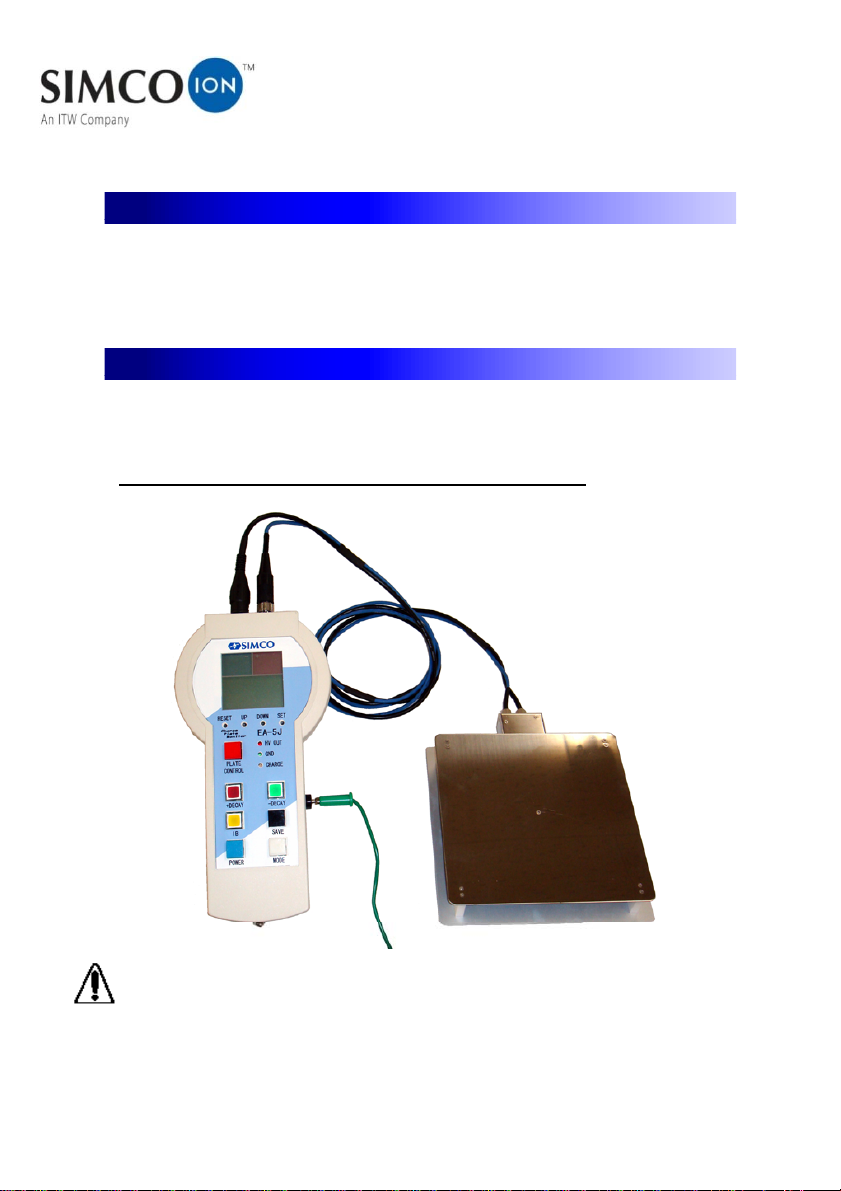
LCD display: Digital numerical value, character, illustration and bar graph are displayed.
Bar graph: It shows the plate voltage and the decay time.
Right side; red LCD for positive polarity
Left side; blue LCD for negative polarity
Resolution of a bar: The value of a bar can be set.
Ion balance measurement: Four types.
15 1 V per a bar , 30 2 V per a bar ,()()
()()150 10 V per a bar , 300 20 V per a bar
Decay time measurement: Five types.
10 s 1 second per a bar , 30 s 2 seconds per a bar ,()( )
60 s 4 seconds per a bar , 120 s 8 seconds per a bar ,()()
()300 s 20 seconds per a bar
Digital display: Numerical value or character is displayed.
Plate voltage: V 0 999 V□□□ ⇒ ~±
. kV 1.00 kV 1.50 kV□□□ ⇒ ± ~±
Decay time: . s 0.0 99.9 seconds□□ □ ⇒ ~
s 100 300 seconds□□□ ⇒ ~
[][]Mode display: Au, Ma, ib Ion Balance , +/- dE Decay time
()The end of measurement: End in Auto mode
Time over: out The plate voltage could not reach to the stop voltage(
)within the setting time during decay time measurement
Error indication: 0 or 1□⇒
Various mode displays: Character or illustration is displayed.
IB ; Ion balance measurement mode[]
HOLD ; Retains display after a measurement[]
ERROR ; Error sign if sensor is damaged[]
Battery condition display 4 stages .()
LED display: HV OUT; High voltage is supplying to the plate.
GND; The plate is grounded.
+Decay, -Decay and IB; Each LED in the buttons lights in the mode.
CHARGE; Red LED: Built-in battery is charging
Green LED: Completely charged
-page7-

Maximum supply voltage: +/- 1,200 V
()Accuracy: +/- 10%, +/- 1 digit Indicated value
Ambient conditions: 10 40 and less than 60 %RH~℃
Beep sounds: Beep sounds when Power is turned on or the measurement end.
Interface: In accordance with USB 2.0.
(Ω)Analog output: Voltage output Load resistance 20 k or more
()Plate voltage 1V / Output voltage 1 mV 0.001 V
Digital zero: The digital display and the bar graph are adjusted to zero automatically by
grounding the plate as initializing when the measurement starts.
External connectors: Signal connectors for the plate sensor.①
HV connector for supplying high voltage to the plate sensor.②
③()USB terminal Type: Mini-B
Data transfer and battery charging by connecting to a personal
computer or an exclusive AC/DC adapter.
④()Analog output terminal mini-Jack 3.5 mm dia.
⑤() ( )Ground GND terminal Banana jack
Power: A personal computer or an exclusive AC/DC adapter.
Operable time: Approx. 30 hours in Ion balance measurement
()× ()× ()[ ]Overall size: 117 W 228 D 47 H mm
Weight: Approx. 410 g
Case material: ABS resin, UL-94B
-page8-

3.2 Sensor plate CPM LPS-
Plate size: 150 150 mm, t = 0.8 mm×
Plate capacity: 20 pF +/- 2 pF
>× ΩInsulation resistance: 1 10
14
Cable length: Signal cable and HV cable; 1.5 m
()× ()× ()[ ]Overall size: 160 W 190 D 26 H mm
()Weight: Approx. 510 g with cable
()()Case material: Stainless steel plate and sensor enclosure and aluminum rear panel
Standards: Meets ANSI/ESD-STM3.1-2000 requirements.
-page9-

Section 4. External view
Front view
Connector side
-page10-

LCD display
Sensor plate CPM-LPS
-page11-

Section 5. Setup
5.1 Setup
Connect the sensor plate to the controller. Be sure that the Plate signal connector and
the HV connector are connected to the controller correctly. For proper measurement,
EA-5J should be grounded on the right side grounding terminal by the grounding lead
provided with the equipment.
CAUTION
If the sensor plate is not connected, the condition setting etc. cannot be done. In this
case, when power is on "ERROR 0" will be displayed.
Connection of the sensor plate
-page12-

5.2 Battery charging
EA-5J has an internal battery. It can be charged by the USB terminal on the right side.
Even charging the measurement can be done. When the POWER button blue is()
pressed, the battery condition is displayed on the left side of LCD as shown in the
figure below. Charge the battery when display shows the battery to be empty.The
charging should be done by using a USB cable to connect to an AC/DC adaptor with
USB terminal or a personal computer. A CHARGE LED lights up in red when charging.
It lights up in green when charging is complete.
Battery condition display
CAUTION
The battery condition display indicator on the display is not proportionaltothe
remaining energy. The battery might rapidly decrease by the battery conditions.
Charge with battery
-page13-

5.3 Initial screen
As POWER button blue is pressed, the sensor plate is()
grounded and automatic measurement mode Au is()
displayed as shown in the right figure. The measurement
mode can be changed by pressing MODE button white as()
shown in the figure below.
Initial display
()⇒ ()⇒ ( )Auto mode Au PC Mode Pc Manual mode Ma
Mode display
5.4 Measurement condition setting
[]Measurement condition setting can be done in ion balance measurement mode ib
yellow and decay time measurement mode dE red /+ Decay or green /-() [](
Decay in the manual mode.)
Manual mode screen
Ion balance mode Positive Decay time Negative Decay time
screen mode screen mode screen
() ( ) (- )IB button +DECAY button DECAY button
-page14-

5.4.1 Measurement condition setting in ion balance measurement mode
When manual mode Ma is displayed, the measurement mode can be changed to()
ion balance mode ib by pressing the ion balance mode button IB yellow .() ( )
Auto mode PC mode Manual mode Ion balance mode
Flow of LCD display
Press SET button function switch by a thin stick 1 2 mm diameter . The() (~ )
three measurement condition can be set with the following procedure.(①~③)
After choosing by pressing UP/DOWN buttons, each setting is saved in the internal
memory by pressing SET button again. When all setting is complete, ion balance
measurement mode ib is displayed again. If MODE button white is pressed the() ( )
display will return to manual mode Ma .()
()How to press the measurement condition setting button SET
-page15-

LCD display renewal rate setting①
EA-5J converts the analog signal from the sensor to digital signal every 20 ms. The
digital signal is calculated automatically except the maximum and the minimum value
according as following four kinds of renewal rate for the length of time.
()LCD display : Renewal rate number of points
()0.2 : 0.2 seconds 10 points
()1.0 : 1.0 second 50 points
()5.0 : 5.0 seconds 250 points
()10.0 : 10.0 seconds 500 points
()Default setting: 0.2
LCD display shows the calculated average value except for the maximum and minimum at
every selected time base.
LCD display
Measuring time setting②
The measuring time for ion balance can be chosen from following four kinds of
setting.
LCD display : Measuring time
10 : 10 seconds
30 : 30 seconds
60 : 60 seconds
con : Continuous
()Default setting: 10
LCD display
-page16-

Bar graph setting③
The correspondence of each bar of the bar graph 15 pcs. for each polarity to the()
voltage can be chosen from following four kinds of setting.
LCD display : Voltage per one bar
15 : 1V
30 : 2V
150 : 10V
300 : 20V
()Default setting: 15
LCD display
5.4.2 Measurement condition setting for decay time measurement mode
When manual mode Ma is displayed, the measurement mode can be changed to()
decay time measurement mode +dE or -dE by pressing the decay time mode()
button red /+ Decay or green /- Decay .()
Positive decay time Manual mode Negative decay time
measurement mode measurement mode
LCD display
Press SET button with a thin stick. The two measurement conditions , can(① ②)
be set with the following procedure. After choosing by pressing UP/DOWN buttons,
each setting is saved in the internal memory by pressing SET button again. The(
measurement conditions are the same setting for both polarity. When all setting is)
complete, decay time measurement mode +dE or -dE is displayed again. If MODE()
button white is pressed the display will return to manual mode Ma .() ()
-page17-

Stop voltage setting①
In the decay time measurement, the EA-5J monitors the time taken for the plate to
discharge from the start voltage 1,000 V to the stop voltage. This stop voltage can()
be set from 5 to 100 V in 5 V increments or decrements by pressing UP/DOWN
()button. Default setting: 100 V
LCD display
Measuring time setting②
The measuring time for the decay time can be chosen from five kinds of the following
setting.
LCD display : Measuring time
10 : 10 seconds
30 : 30 seconds
60 : 60 seconds
120 : 120 seconds
300:300seconds
()Default setting: 10
LCD display
5.5 Sensor plate placement
After all settings are complete, turn the power off by pressing POWER buttonblue.()
Place the sensor plate in front of an ionizer for the measurement. Refer the standard like
"ANSI/ESD-STM3.1-2000" to confirm positions and the distance from the ionizer to the
sensor plate. Use threads on the back of the sensor plate for installing a tripod of
camera etc. See a photograph in the next page for reference about the position of the
ionizer, EA-5J controller and the sensor plate.
-page18-

Threads on the back of the sensor plate
Measurement scenery
-page19-
Table of contents
Other ITW Measuring Instrument manuals