ItWatchDogs SA-1 Operation manual

SA-1
SMOKEALARM
installation & user guide

1
SA-1 Smoke Alarm
A smoke alarm is an excellent safety device – and with the IT Watchdogs’ SA-1, not only will you have the
usual audible alarm signal if something in your installation begins to smoke, but your WeatherGoose monitoring
system will be able to notify you via e-mail or SNMP as well, just like any other monitored sensor! This makes
the SA-1 an especially valuable add-on for monitoring remote installations which might not have anyone around
to hear the siren.
Plus, since the Kidde smoke alarms the SA-1 is based around are capable of being connected to other smoke
alarms as a group, such that if one senses smoke, they all sound off (a very important feature for large commercial
buildings where a single alarm wouldn’t be loud enough to be heard throughout the facility), an SA-1 can be wired
up alongside other compatible Kidde smoke alarms such that any smoke alarm in your facility can trip the alarm
threshold on the WeatherGoose unit and send an alert. (In fact, it is exactly this remote “daisy-chaining” function
which the SA-1 taps into in order to provide a signal to the WeatherGoose; the actual Kidde smoke alarm device
is not modified by IT Watchdogs in any way.)
The SA-1 is directly compatible with any WeatherGoose (series I or series II) monitoring unit which has
analog-sensor inputs; such models include the WeatherGoose, SuperGoose, and the MiniGoose/XP. Models
which do not have built-in analog inputs, such as the MiniGoose, will require the use of an appropriately-
programmed CCAT analog-to-digital converter to use an SA-1. Models which do not provide connections for
either analog or digital sensors, such as the MicroGoose, are not compatible with the SA-1 Smoke Alarm.
A typical example of the SA-1 Smoke Alarm is shown below. Note that because the SA-1 is based around a
standard off-the-shelf Kidde smoke alarm, your particular unit may have some cosmetic differences from the one
shown below. Its functionality, however, will be the same.
SA-1 Smoke Alarm users’ guide – Rev. A-101 (Oct. 2010)

2
The SA-1 is powered both by a 120VAC wall plug, and by a 9V backup battery which keeps the unit alive
and functioning in the event of a line-power failure. This means that as long as your WeatherGoose and its
associated network & internet gateways are also kept alive via a UPS or auxiliary generator during a power
failure, then you will still receive e-mails and/or SNMP trap events if smoke should be detected.
CAUTION: the SA-1 is not designed for worldwide-voltage operation,
and is not compatible with 208VAC or 240VAC line voltages!
The Kidde smoke alarms that the SA-1 is designed around are only rated and sold for use in North America,
and are only designed to function on standard 120VAC/60Hz line voltages. Attempting to operate the SA-1 from
higher voltages, and/or from 50Hz line frequencies, may permanently damage or destroy the smoke-alarm unit.
As with any smoke alarm device, IT Watchdogs strongly recommends that you make a note of when the SA-1
was first installed, test it at regular intervals, and replace it on the schedule recommended by the smoke alarm’s
manufacturer. The manufacturer’s recommended testing and replacement schedules can be found on the body of
the smoke alarm itself; simply twist the smoke alarm to unlock it from the mounting base (an arrow molded into
the plastic body will show the correct direction), then look at the manufacturer’s labeling on the back of the unit.
Lorem
ipsum dolor sit amet,
consectetur adipisicing elit, sed do
eiusmod tempor incididunt ut labore et dolore
magna aliqua. Ut enim ad minim veniam, quis nostrud
exercitation ullamco laboris nisi ut aliquip ex ea commodo
consequat. Duis aute irure dolor in reprehenderit in voluptate
velit esse cillum dolore eu fugiat nulla pariatur. Excepteur sint
occaecat cupidatat non proident, sunt in culpa qui officia deserunt
mollit anim id est laborum.
...and follow the manufacturer’s
periodic testing and replacement
recommendations listed on the
back of smoke alarm unit
twist the smoke alarm unit to
dismount it from the base...
...remove the smoke alarm
unit from the base...
This same procedure can be used to access the battery compartment to install or change the 9V backup battery,
if yours is one with the battery compartment located on the back of the unit. (The location of the battery
compartment may vary depending on smoke alarm model.) Be certain to follow all manufacturer’s
recommendations as to how to open the battery compartment, and how often the battery should be changed.

3
ŸConnecting the SA-1 to the Analog-Input terminals:
The following diagrams demonstrate how to connect your SA-1 Smoke Alarm directly to the spring-loaded
analog-input terminals used on most of the standard series-I and series-II WeatherGoose product lines. (Note that
specialized models, such as the PowerGoose and RelayGoose, use different styles of terminal blocks; while the
connections will be the same electrically, the mechanical nature of the connector will be different than the one
shown here. If necessary, refer to the manuals for those specific models for further details on how to connect
analog sensor devices.) Each terminal consists of two openings; a larger, square opening at the bottom, where the
wire will be inserted, and a smaller, narrower opening above which is used to open the spring-loaded jaws inside
the terminal block so the wire can be inserted.
Note that the terminal jaws are not of an insulation-piercing type, and the wire ends must be stripped at least
½” prior to insertion.
First, insert a small flat-
blade screwdriver into
the upper slot...
...pry upwards to open
the spring-loaded jaw...
...slip the sensor wire
into the larger bottom
opening...
...then pull out the
screwdriver to allow the
jaw to close around and
grip the wire.
C C
1 2 3
Red wire (+) can go into
any numbered terminal
This diagram shows the correct polarity to connect an SA-1
to the analog-input terminals on a WeatherGoose.
Note that this applies to all models of the WeatherGoose family,
regardless of series or model; the SA-1 must be connected with
the correct polarity, or the unit will not function and the Goose’s
input circuitry could be damaged by incorrect connections!
Black wire (-) can go
into either C
(common) terminal
CAUTION: unlike some types of analog sensors, the
SA-1 cannot be “doubled up”; i.e. you cannot
connect two or more of them in series or parallel so
that they share a single analog input! Attempting to
do so can damage both the sensors, and possibly the
WeatherGoose analog inputs as well!

4
ŸSensor operation and behavior:
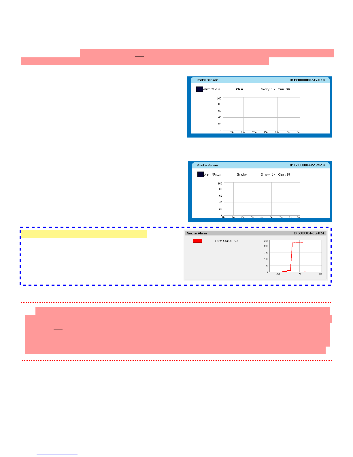
Once you’ve successfully connected the SA1 to your
WeatherGoose, the internal-sensors display block of the
Sensors page will look something like this: (NOTE: for
purposes of this example, the SA-1 has been connected to
Analog Input #1 of a WeatherGoose-II with v3.3 firmware;
the use and operation of the SA-1 will be similar for other
models, but the on-screen displays may differ somewhat.)
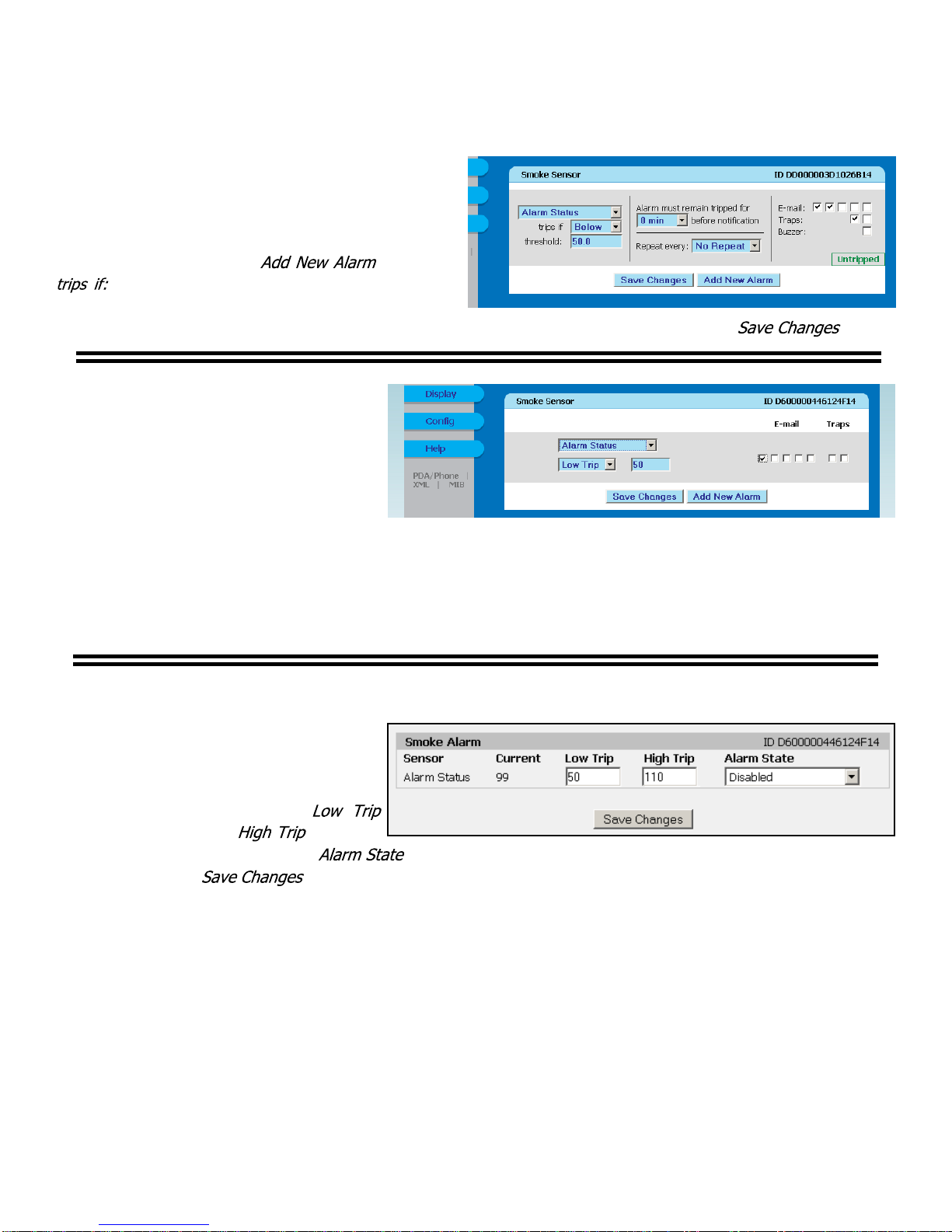
In this screenshot, the SA-1 is currently dormant; no
smoke has been detected, so the alarm is quiet and there is
no signal to the WeatherGoose...
So, if the alarm is inactive, why does the reading show
“99”, instead of “0” as you might normally assume? This
is just a consequence of the way the internal Analog Inputs
are designed to accommodate both dry-contact devices
such as switches, relays, etc., and voltage-signal devices such as current transformers. Since the SA-1 presents
itself as a dry-contact type of device, the analog input reads “99”, because its contacts are currently in the “open”
state and, due to the presence of a weak pull-up resistor which supplies loop current for dry-contacts connected
to the Analog Input terminals, an “open” terminal will tend to float up to +5V – and since the WeatherGoose
displays the Analog Inputs’ 0~5VDC input range as a proportional value from 0~99, an open contact pair reads
as “99”.
Here, the smoke alarm has detected smoke in the air (or
someone has held down the test button), and the SA-1’s
contacts have closed. Note that the reading hasn’t quite
gone all the way to “0”, but that’s not unusual; depending
on the length of the wire between the WeatherGoose and
the SA-1, there may be a few ohms of resistance in the wire
that keep the input from getting all the way down to 0VDC.
(Oxidization on the wire terminals can also cause this,
which is why it is important to ensure that the wires are
cleanly stripped and that the WeatherGoose unit is not
mounted in an area which is exposed to excessive humidity
or airborne chemical contaminants. Since the SA-1 is
simply a “Yes/No”-type of sensor, though, a slight
variation in readings doesn’t matter – effectively, any
reading >50 can be considered “inactive”, and anything <50
can be read as “alarm.”

5
If you are using a Series-I unit:
The alarm thresholds are the same as for
series-II, but the method of setting them is
somewhat different. Find the sensor block
on the Alarms page for the Goose unit’s
internal sensors, then set the
threshold to 50 and the threshold
to 110, as shown here, for the input which
the SA-1 is connected to, then set the
to the action you wish to take place
when the trip threshold(s) are exceeded and
click . (The input being used is highlighted here for example purposes.) Since the Analog input
cannot go higher than 99, this will effectively disable the High Trip event, which is not needed in this application.
If you are using a Series-II unit:
To set an alarm threshold to notify you when a
door is opened, simply go to the Alarms page, click the
button under the Goose’s internal-
sensors block, Analog Input to which the RCP2-100 is
connected (Analog-1 in this example), set to
Below and threshold to 50; then, set the checkboxes
for the alarm actions you wish this alarm threshold to
trigger, along with a trigger delay or alarm-repeat
interval if desired, and click .
If you are using a Series-II unit with
a firmware revision prior to v3.4.x, your
alarm-settings block will look like this.
Alarm-threshold settings are calculated and
programmed the same way as above; the
only difference (aside from the lack of
trigger-delay and alarm-repeat intervals,
which were introduced in v3.4) is that the
alarm types are named High Trip and Low Trip instead of Above and Below, respectively. High Trip alarms
are tripped when the reading goes higher than the set threshold, while Low Trip alarms are tripped when the
reading goes below the threshold.
ŸAlarm-threshold settings when connected directly to an Analog Input:

6
RD
BK
red wire goes into the terminal marked RD or (+)
black wire goes into the terminal marked BK or (-)
ŸConnecting the SA-1 to the CCAT-SMOKE:
If you are using an ITWatchdogs monitoring device which does not have built-in analog inputs, such as the
MiniGoose-II, or if you have already used up all of your analog inputs on other sensors, then you will need to
attach the SA-1 via an appropriately-programmed CCAT analog-to-digital bus interface module, available from
IT Watchdogs. The following diagrams show how to hook up and use an SA-1 in combination with a
CCAT-SMOKE interface module.
(Note: the CCAT has been manufactured in a couple of different physical variations over the lifetime of the
product. If your CCAT does not seem to match the appearance of the one shown below, you may have an earlier
model, and may wish to consult the CCAT User Guide to insure the correct hookups.)
Note that the same cautions apply to using the CCAT as to the internal Analog Inputs; i.e. correct polarity
must be observed when connecting the SA-1, and multiple units may not be connected in series or parallel to share
a single CCAT connection! Again, the wires will need to be stripped, as the terminals are not of an insulation-
piercing type. However, they do not need to be stripped back as far as they do for the Analog Input block; a
¼-inch of exposed wire will generally be sufficient for the style of terminals used on the CCAT.

7
NOTE: THERE IS A BUG IN SOME OLDER SERIES-II FIRMWARE VERSIONS WHICH CAUSES
THE UNIT TO DISPLAY THE STATUS INCORRECTLY; i.e. the “Smoky” and “Clear” states are reversed!
This does not affect the device’s actual operation or the ability to set alarm thresholds; it is merely a cosmetic
issue with the “friendly” naming of the actual numeric values from the CCAT-SMOKE. However, it can be
confusing, so if you find that your device is displaying the SA-1’s status opposite of what it should be, IT
Watchdogs highly recommends updating your unit to the latest firmware revision at the soonest opportunity.
ŸSensor operation & behavior when connected via a CCAT-SMOKE:
Once you’ve connected the CCAT-SMOKE to the monitoring unit, a new sensor block will appear, initially
titled “Smoke Sensor.” (This name can, of course, be changed from the Display page to something more specific
to your installation.) If your CCAT does not initially display as “Smoke Sensor”, do not proceed further, as your
CCAT is not correctly programmed for this sensor and will not display its status properly! (In this event, contact
IT Watchdogs technical support for assistance.)
This screenshot shows an inactive smoke alarm, so the
WeatherGoose displays the SA-1’s status as “Clear.” The
actual numeric value being graphed is “99” – this is because
the CCAT’s A/D converter behaves essentially the same
way as the built-in Analog Inputs on the WeatherGoose; i.e.
an open dry-contact input tends to “float” to 5VDC due to
an internal pull-up resistor, and 5V is interpreted and
displayed as “99”. However, since the CCAT and
WeatherGoose “know” that the connected device is supposed to be an SA-1 smoke alarm, it is able to interpret
the number and present a more user-friendly display.
Now, let’s see what happens when we activate the
smoke alarm. The numeric reading drops down towards 0,
and the SA-1’s status is indicated as “Smoky.” (If you are
conducting a test of the SA-1, you will probably want to hit
“refresh” on your browser a few seconds after the alarm
begins to sound, rather that wait for the automatic 1-minute
page refresh.)
Special note for series-I WeatherGoose users:
Series-I models will not display the “smoky” or
“clear” labels described above; instead, they will simply
display the same numeric values as described in the
previous section on analog inputs, as shown here.

8
If you are using a Series-I unit:
The alarm thresholds are the same as for
series-II, but the method of setting them is
somewhat different. Find the sensor block
on the Alarms page for newly-connected
CCAT-SMOKE, then set the
threshold to 50 and the threshold
to 110, as shown here, then set the to the action you wish to take place when the trip threshold(s) are
exceeded and click . Since the reading on a CCAT analog-to-digital input channel cannot go higher
than 99, this will effectively disable the High Trip event, which is not needed in this application.
If you are using a Series-II unit:
When you go to the Alarms page, you’ll find that
a new parameter block has been added there as well,
also titled “Smoke Sensor.” To set an alarm
threshold to notify you when the SA-1 detects smoke
and sounds the alert, simply scroll down to this new
parameter block, click the button, set
to Below and threshold to 50; then, set the
checkboxes for the alarm actions you wish this alarm
threshold to trigger, along with a trigger delay or alarm-repeat interval if desired, and click .
If you are using a Series-II unit with
a firmware revision prior to v3.4.x, your
alarm-settings block will look like this.
Alarm-threshold settings are calculated and
programmed the same way as above; the
only difference (aside from the lack of
trigger-delay and alarm-repeat intervals,
which were introduced in v3.4) is that the alarm types are named High Trip and Low Trip instead of Above
and Below, respectively. High Trip alarms are tripped when the reading goes higher than the set threshold,
while Low Trip alarms are tripped when the reading goes below the threshold.
ŸAlarm-threshold settings when connected via a CCAT-SMOKE:
Table of contents