4/6
2. ChannelLockFunction
2.1At“ChannelLock”mode,holdpressthe[Fun]+[Up]orpress[Fun]+[Down]button6seconds,itwillexitthe
“ChannelLock”function,the“keylock”iconofLCDdisplaywillbeoff.
2.2At“ChannelLockOff”mode,if10secondsdon’tpressanybutton,itwillgotothe“ChannelLock”modeagain.
2.3At“ChannelLockOff”mode,holdpress[Fun]buttonmorethan6seconds,itwillgothe“ChannelLock”mode.
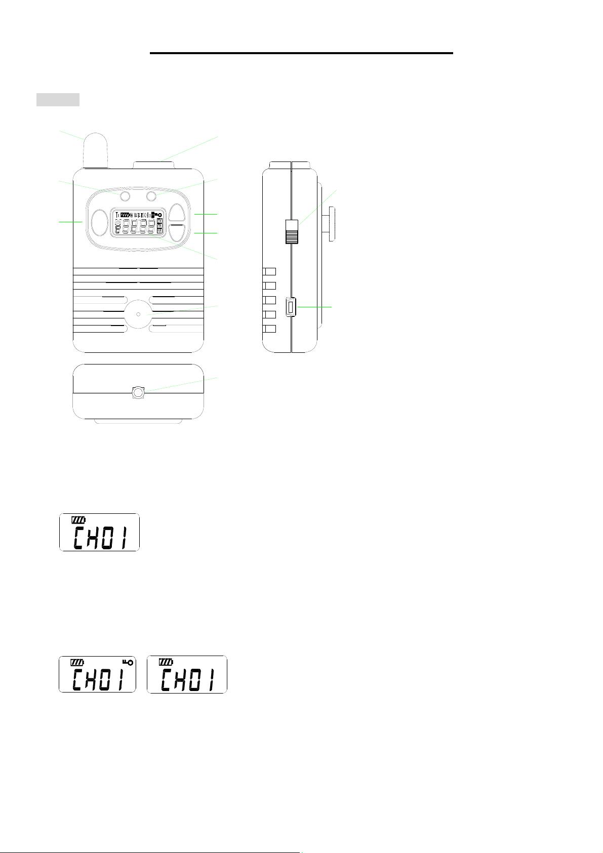
3. ChooseOperatingChannel
Beforechooseanewoperatingchannel,youhavetoexitthe“ChannelLock”mode.Press[Up]or[Down]buttonto
choosethedesiredchannelfrom“CH01”to“CH99”,holdpressthe[Up]or[Down]buttontospeedupthechannellist,
afterreleasethebutton,if10secondsdon’tpressanybutton,itwillgotothe[ChannelLock]modeautomatically.
4.DeviceStatus&LEDindicator
4.1Standbymode(RX):The“In‐use”LEDoff,thedevicemutethe“AudioOut”pin,“In‐use”pinis“high”level.
4.2Signalconnectingstatus:WhendevicereceiveTXinquirysignal,the“Busy/Tx”LEDisblinkingeach0.2second,
“In‐use”pinishighlevel.
4.3“TransmitON”status:Afterconnectingsuccess,the“In‐use”LEDON,“Busy/TX”greenLEDON,the“AudioOut”
pinisun‐mutethatwillsendoutthevoicesignal,the“In‐use”pinis“Low”level&“RadioOpen”pingoes“Low”.
4.4Devicedis‐connectingstatus:When“RadioOpen”pinchangefrom“Low”to“High”,the“Busy/Tx”LEDchange
fromRedtoGreen.
4.5Device“dis‐connect”status,the“In‐use”LEDoff,“Busy/TX”LEDoff,the“In‐use”pingoeshigh,“RadioOpen”pin
goes“high”also,the“AudioOut”pingoestomute.
5.RXConnectCommand
5.1Atstandbystatus,“RadioOpen”pinchangefrom“High”to“Low”,RXwillsendthe“Transmit”codetoTXdevice,
itgoestothe“connecting”status.
5.2WhenRXreceivedtheconfirmedcodefromTXdevice,RXdevicegoestothe“TransmitON”status.
5.3IfRXdoesn’treceivedtheconfirmedcodefromTXwithin6seconds,RXwillre‐sendthe“Transmit”codethatbe
repeat3times,thenthe“RadioOpen”pincouldchangeto“High”&devicegotothe“standby”mode.
6.RXDis‐connectCommand
6.1At“TransmitON”status,“RadioOpen”pinchangefrom“Low”to“High”,TheRXdevicewillsendthe“Transmit
OFF”codetoTXdevice,itwillgotothedis‐connectingstatus.
6.2WhenRXreceivedtheconfirmedcodefromTX,itwillgotothestandbymode.
6.3IfRXdonotreceivedtheconfirmedcodefromTXwithin6seconds,RXwillre‐sendthe“TransmitOFF”code
thatberepeat3times,thengoestostandbymode.
7.LCDBackLight
Pressanybuttonwillturnonthebacklightindicator,itwillbe“OFF”if8secondsdon’tpressanybutton.
8.PCProgramtheparameter
8.1AlloftheoperatingchannelbothTX&RXhavetopre‐programbyPCbeforeusing.
8.2TherearethreeAudiooutputlevelsisabletochoosebyPCbeforeusing,thedefaultsettingis“Mid”.
FCCCaution:
AnyChangesormodificationsnotexpresslyapprovedbythepartyresponsibleforcompliancecouldvoidthe