IVT AY-XP12JHR-N User manual

SERVICE MANUAL
AYXP12JHRN
This document has been published to be used for
after sales service only.
The contents are subject to change without notice.
CHAPTER 1. SPECIFICATION
[1] SPECIFICATION............................................ 1-1
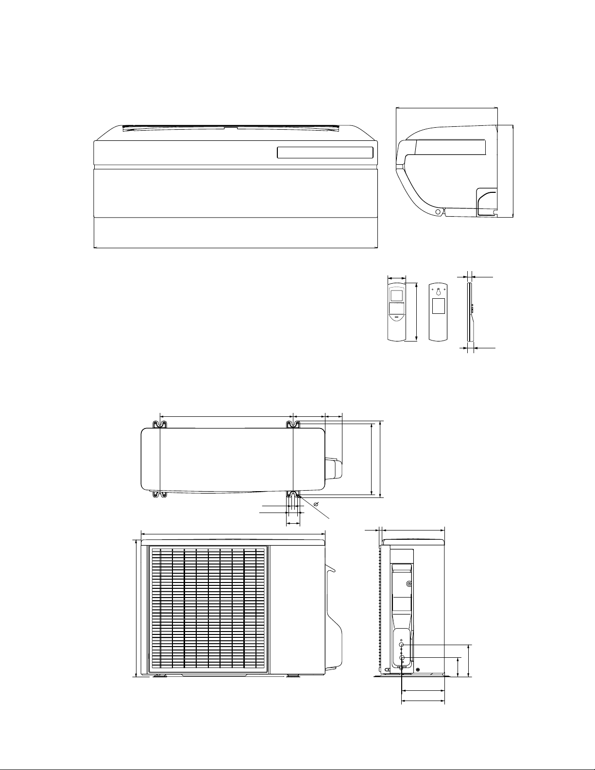
[2] EXTERNAL DIMENSION............................... 1-2
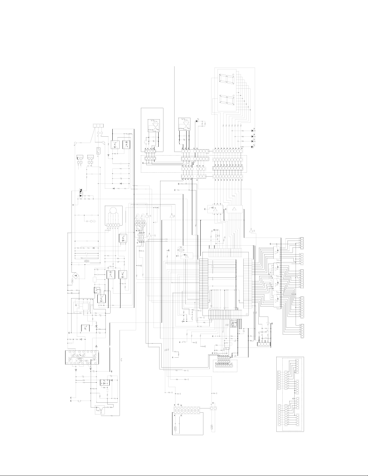
[3] WIRING DIAGRAM ........................................ 1-3
[4] ELECTRICAL PARTS .................................... 1-3
CHAPTER 2. EXPLAMATION OF CIRCUIT AND OP-
ERATION
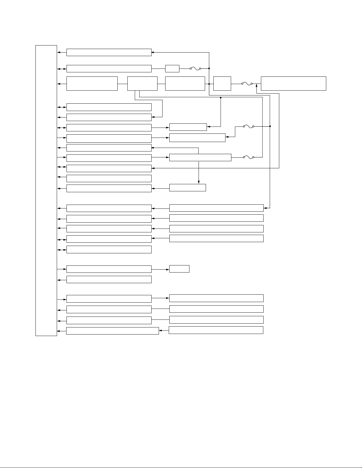
[1] BLOCK DIAGRAMS....................................... 2-1
[2] MICROCOMPUTER CONTROL SYSTEM........ 2-3
[3] FUNCTION..................................................... 2-9
CHAPTER 3. FUNCTION AND OPERATION OF PRO-
TECTIVE PROCEDURES
[1] PROTECTION DEVICE FUNCTIONS AND
OPERATIONS................................................ 3-1
[2] AIR CONDITIONER OPERATION IN
THERMISTOR ERROR ................................. 3-3
[3] THERMISTOR TEMPERATURE CHAR-
ACTERISTICS ............................................... 3-5
[4] HOW TO OPERATE THE OUTDOOR
UNIT INDEPENDENTLY................................ 3-6
[5] GENERAL TROUBLESHOOTING CHART........3-6
[6] MALFUNCTION (PARTS) CHECK METH-
OD .................................................................3-8
[7] OUTDOOR UNIT CHECK METHOD...........3-10
[8] TROUBLESHOOTING GUIDE ....................3-13
CHAPTER 4. REFRIGERATION CYCLE
[1] FLOW FOW REFRIGERANT ........................4-1
[2] STANDARD CONDITION ..............................4-1
[3] TEMPERATURE AT EACH PART AND
PRESSURE IN 3-WAY VALVE ......................4-1
[4] PERFORMANCE CURVES...........................4-2
CHAPTER 5. DISASSEMBLING PROCEDURE
[1] DISASSEMBLY OF INDOOR UNIT...............5-1
[2] DISASSEMBLY OF OUTDOOR UNIT.........5-10
Parts Guide
TopPage
CONTENTS
SPLIT TYPE
ROOM AIR CONDITIONERS
OUTDOOR UNIT
AE-X12JR-N
In the interests of user-safety (Required by safety regulations in some
countries) the set should be restored to its original condition and only
parts identical to those specified should be used.
INDOOR UNIT
AY-XP12JHR-N
MODELS

AYXP12JHRN
1 – 1
AYXP12JHRN Service Manual
CHAPTER 1. SPECIFICATION
[1] SPECIFICATION
1. AY-XP12JHR-N – AE-X12JR-N
NOTE: The conditions of star”✩” marked item are based on ‘EN14511’.
MODEL INDOOR UNIT OUTDOOR UNIT
ITEMS AY-XP12JHR-N AE-X12JR-N
Rated cooling capacity (Min– Max.) kW 3.5 (0.9 - 4.0)
Rated heating capacity (Min–Max.) kW 4.6 (0.9 - 6.5)
Moisture removal (at cooling) Liters/h 1.2
Electrical data
Phase Single
Rated frequency Hz 50
Rated voltage V 220-240
Rated current ☆
(Min - Max.) Cool A 4.2 (0.9 - 5.7 )
Heat A 5.0( 0.9 - 7.4 )
Rated input ☆
(Min - Max.) Cool W 920 (200- 1250)
Heat W 1075 (160 - 1700)
Power factor ☆Cool % 95
Heat % 93
Maximum operating current A 9.6
Compressor Type Hermetically sealed rotary type
Model DA111A1F22F
Oil charge 450cc (Ester oil VG74)
Refrigerant system Evaporator Louver Fin and Grooved tube type
Condenser Corrugate Fin and Grooved tube type
Control Expansion valve
Refrigerant (R410A) 1140g
De-lce system Micro computer controled reversed systems
Noise level
(at cooling/heating) High dB(A) 40 47
Low dB(A) – –
Soft dB(A) 27 –
Fan system
Drive Direct drive
Air flow quantity
(at cooling/heating) High m3/min. 9.3 32.2
Low m3/min. 7.6 –
Soft m3/min. 5.2 –
Fan Cross flow fan Propeller fan
Connections
Refrigerant coupling Flare type
Refrigerant tube size Gas, Liquid 3/8", 1/4"
Drain piping mm O.D φ18
Others
Safety device Compressor: Thermal protector
Fan motors: Thermal fuse
Fuse, Micro computer control
Air filters Polypropylene net (Washable)
Net dimensions Width mm 790 780
Height mm 260 540
Depth mm 290 265
Net weight kg 11 36

AYXP12JHRN
1 – 2
[2] EXTERNAL DIMENSION
1. Indoor unit
2. Outdoor unit
㧔Unit㧦㨙㨙㧕
798
260
290
22.0
58 18.5
175
INVERTER AIR CONDITIONER
265
780
540
14
167.5
165
540
299
72
58
37.5
12
4.5
324
135
81
136

AYXP12JHRN
1 – 3
[3] WIRING DIAGRAM
1. Indoor unit
2. Outdoor unit
[4] ELECTRICAL PARTS
1. Indoor unit
2. Outdoor Unit
DESCRIPTION MODEL REMARKS
Indoor fan motor MLB395 DC Motor
Indoor fan motor capacitor – –
Transformer – –
FUSE1 – QFS-GA078JBZZ (250V, 3.15A)
DESCRIPTION MODEL REMARKS
Compressor DA111A1F22F D.C. brush-less motor
Outdoor fan motor MLB078 DC Motor
Outdoor fan motor capacitor – –
Fu4 – QFS-GA064JBZZ(250V, 1A)
Fu3 – QFS-GA051JBZZ(250V, 2A)
Fu2 – QFS-GA052JBZZ(250V, 3.15A)
Fu1 – QFS-CA001JBZZ(250V, 20A)
Fu5, 6 – QFS-CA002JBZZ(250V, 15A)

AYXP12JHRN
2 – 1
AYXP12JHRN Service Manual
CHAPTER 2. EXPLAMATION OF CIRCUIT AND OPERATION
[1] BLOCK DIAGRAMS
1. Indoor unit
AC power
Rectification circuit
CPU
3.15A
Fuse
DC power supply circuit
Fan motor PWM control circuit
Rotation pulse input circuit
AC clock circuit
Remote controller signal reception circuit
Buzzer drive circuit
CPU reset circuit
CPU oscillator circuit
Room temp. detect circuit
Heat exchanger pipe thermo circuit
EEPROM
Select circuit
Serial I/O circuit
Auto restart circuit
Test run circuit
Auxiliary mode
Power on circuit
Cluster generator drive circuit
Indoor fan motor
Fan motor pulse detect
Wireless remote control operation
Audible operation confirmation
Room temp. thermistor
Heat exchanger pipe thermistor
Louvre angle, fan speed
Wireless, preheat, Model select
Indoor/outdoor control signal I/O
Test run (forced operation)
Auxiliary mode button ON/OFF
Self diagnostics, fault diagnosis
Cluster generator
Unit-unit wiring
(AC power and
serial signals)
LED Drive circuit LED display
Louver motor drive circuit (Horizontal)
Louver motor drive circuit (Vertical, right)
Louver motor drive circuit (Vertical, left)
How direction control (Horizontal louver motor)
How direction control (Vertical louver motor,right)
How direction control (Vertical louver motor,left)

AYXP12JHRN
2 – 2
2. Outdoor unit
CPU
20A
protection
15A
protection
Expansion valve drive circuit Expansion valve
Suction temp. thermo. circuit Suction pipe thermistor
2-way valve temp. thermo. circuit 2-way valve thermistor
3.15A
protection
15A
protection
Power supply circuit
CPU oscillator circuit
DC overvoltage detection circuit
Outdoor fan drive circuit
4-way valve relay drive circuit
Power transistor module drive circuit
Serial I/O circuit
CPU reset circuit
Position detection circuit
AC overcurrent detection circuit
Compressor thermo circuit
Heat exchanger pipe thermo circuit
Outdoor temp. thermo. circuit
LED drive circuit
Test mode circuit
Power factor
converter circuit
Filter
circuit
Smoothing
circuit
Pulse amplitube modulation circuit
EEPROM
AC clock circuit
DC overcurrent detection circuit
IGBT
Unit-unit wiring (AC power
and serial signals)
Outdoor fan
4-way valve
Power transistor module
Compressor
Current transformer
Compressor thermistor
Heat exchanger pipe thermistor
Outdoor temperature thermistor
LED
Terminal board, Terminal fuse, circuit Terminal board, Terminal fuse

AYXP12JHRN
2 – 3
[2] MICROCOMPUTER CONTROL SYSTEM
1. Indoor unit
1.1. Electronic control circuit diagram
LED
301
R318
180 1W
FULL
POWER
OUTDOOR
TEMP
LED
304
LED
302
LED
303
R317
360
1W
R316
100
1W
R315
100
1W
RED
YELLOW
GREEN
SG301
OPERATION
TIMER
GREEN
1W 560
f2
b2
COM2
COM1
12
13
15 14 3 2 1 16 4
a1 b1 c1 d1 e1 f1 g1
g2
g1
f1
e2
e1
d2
d1
c2
c1
b1
a2
a1
R304
R305
R306
R307
R308
R309
R310
1W 560
1
2
3
4
5
6
7
8
9
10
g2
f2e2d2c2b2a2
811567910
BCN301
1W 180
1W 180
1W 560
1W 180
1W 180
R128
1K
TERMINAL
BOARD 3P
DC
FAN
MOTOR
AUTO
RESTART
SELECT
0.01uF
250Vx2
275V 0.1uF
C12A
C12B 275V 0.1uF
NC
NC
NC
CLUSTER
BCN602
0.1uF
47uF
50V 1000p
10.0KF
47K
25V
10V
100uF
25V
47K
CN90
1000p
0.1uF
0.1uF
0.1uF
0.1uF
0.1uF
0.1uF
0.1uF
0.1uF
0.1uF
1uF
P83
P82
P81
P80
P05
P06
P70
P71
P72
P73
P74
P75
P76
P77
P67
P66
P65
P64
P31
P63
P62
P61
P60
VDD1
1
2
3
4
5
6
7
8
9
10
11
12
13
14
15
16
17
18
19
20
21
22
23
24
25
26
27
28
29
30
80
79
78
77
76
75
74
73
72
71
70
69
68
67
66
65
P140
P141
P142
P143
P144
P145
64
63
62
61
60
59
58
57
56
55
54
53
52
51
P00
P01
P02
P03
P04
P131
P130
P20
P21
P22
P23
P24
P25
P26
P27
P150
P151
P152
P153
P154
P155
P156
P157
AVS S
VSS1
P30
P87
P86
P85
P84
0.01uF
25V
25V
25V
25V
25V
0.1uF
0.01uF
0.01uF
NC
0.1uF
100uF
10V
4.7K
4.7K
1K
R93
100K
C90
R90
7.5K
4.7K
4.7K
10K
10K
6.8KF
0.1u
50V
100u
35V
25V 0.1u
1M
1/4W
3.3K
910x2
WIRELESS
47K
4.7Kx2
POWER
MODEL
BZ1
1/4W
1.8K
KRC108S
KRC108S
NF1
D1N60
11K 2W
4.7K
56K
TEST
4.7K
4.7K
CLUSTER
4.7K
4.7K
6.8KF
3.3K
3.3K
6.8K
56K
16V47uF
10K
6.8K
R6
R7 100K
R8
R17
R19
R18
R29
R31
R32
R34
R37
R36
R71
R76
R77
R78
R80
R81
R86
R88
R95
R96
R100
R101
R108
R109
R110
R111
R112
R114 10KF
D2
R105
R107
ZD1 HZ24-2
C1 35V100uF
C2 35V0.047uF
C3 50V0.01uF
C15
C16
C17
C18
C41
C42
C43
C44
C45
C46
C58
C59
C62
Q13
Q14
Q15
47K
JP8
JP9
JPW
R118
R119
R120
R40
DB1
D2SBA60
1/2W 1MX2
1K
1K
R85
R84
R41
1/2W 1M
C12 275V 0.1uF
NR1
R27 R26
C5 0.01u
250V
R9
Q11
KRC106S
R97
4.7K
25V
0.1uF
C13
R38
100K
R39
16V
C301
C302
R83
10K
D4
D1N60
39K
R28
1/2W
200K 1/2W
200K
R94
1K
C61
0.1uF
KRC108S
1/4W
R302
R303
LED310
3.6Kx2
R121
10K
25V
4.7uF
C60
R11 R10
2.7K
KID65004AF
NC
0.1uF
1000pF
C65
C66
50V 1000p
0.1uF
0.1uF
25V
25V
47K
C402
C401
25V
16V
KID65004AF KID65004AF
25V 0.1uF
47uF
KID65004AF
KID65004AF
KID65783AF
C67
R116
10K
R127
4.7K
4.7K
47K
JP1
47K R125
KID65004AF
10KF
2W
11K
JP2
NC
NC
CN1
21
64
4
5
11
OSC1
8MHz
5V
10K
9
50V
50V
10V
P110
P50
AVR 1
AVR 0
P111
P51
P52
P53
P54
P55
P56
P57
P17
P16
P15
P14
P13
P12
P11
P10
50
49
48
47
46
45
44
43
42
41
40
39
38
37
36
35
34
33
32
31
99
98
97
96
95
94
93
92
91
90
89
88
87
86
85
84
83
82
81
100
P120
P47
P46
P45
P44
P43
P42
P41
P40
REST
P124
P123
FLMD
X2
X1
REGC
VSS
VSS0
VDD
VDD0
25V
25V
25V
25V
25V
50V
50V
NC
25V
NC
106S
KRC
4
3
1
2
R92
470
5.1K
R91
HAJP
12V
KIA7815
5V
5V 1K
5V
5V
12V
SW401
SAFETY SW
0.01uF
50V
2
1
PC81716NIP
1Vs
Vcc
2
7Vm
GND
5
3PG
1
1
23
4
4
D1N60
2
N
1
2W
10K
1
2
3
4
5
GND
RESET
TOOL0
FLMD0
1
2
3
680
4
PC817XP3
3
1
32
PC817XP3
4
41
28.2K
680
TH1
PIPE TEMP
TH2
R33
R35
R57
R70
R73
R79
R98
R99
R102
R113
R117
D1
ROOM TEMP
IC1
1K
1K
1K
R106
R104
PC4
PC5
PC6
PC7
CN3
C14
C40
C47
C48
C49
C50
C51
C52
C53
C54
C55
C56
Q2
IC13
IC5
10K
KRA224S
R63
8
CN1
NTC1
10D
SSR1
PR32MA11NXPF
R16
R1 3.3K
3.15A-250VFU1
TOOL1
VDD
5V
2M
R74
R75
1K
9
889
IC9
Q10
12V
IC11
CN18
IC12
12V
R82
10K
1
2
PC817XP3
4
3
PC1
PC817XP3
SERIAL SIGNAL CIRCUIT
PC853HXP
32
PC2
+
R301 IC301
5V
CN17
CN10
47
BCN10
CN11
BCN302
PC
73
82
91
10
6
12
8
10
9
8
7
6
5
4
3
2
1
1
3
4
5
6
7
8
7
6
5
4
3
1
8
12345678
9
8
IC7
R122
R124
R123
10K
10K
10K
6
TXD0
RXD0
54321
BLUE
S
C
B
A
5V
2
2
8
7
6
5
4
3
2
1
1
2
3
4
5
6
7
8
9
10
8
6
1
2
3
11
77
C68
50V
PAN E L
SW1
SW2
PAN E L
1
2
5V
2
3
4
1
2
3
4
1
47 IC401
R401
+
987654321 54321
LOUVER M H
THERMISTOR
THERMISTOR
IC8
6
CN13 CN14 CN15 CN16
BCN401
CN15
R134
R132
R135
R133
5V
BR
BK
WH
RD
1K
1K
13
99
5V
D18
55
6
5
4
3
2
1
CN17
FLASH
11
9
10
5V
10
9
11
2
1
2
1
2
1
CN608
CN609
BCN604
10
9
8
7
6
5
4
3
2
1
5V
13
11
12
10
9
8
7
12V
5V
BCN602
BCN601 CN601
CN602
CN603
CN19
12345
IC14
9
8
12345678
987654321
CN15
CN14
6
6
54321
HANG M R
HANG M L
54321
123456789 87654
321
12345
PANEL M L PANEL M R
12345
BCN603 BCN604
CN604 CN605 CN606 CN607
4.3KF
R129
10K
1W 100K
BLUE
R137 680
EC7
C8
C6
G(Y)
10KF
Q3
KRA106S
R51
2.7K
R52
1.5K
R89
2.2M
R72
6.8K
R61
3.3K
R64
3.3K
R136
56K
IC3
KIA431
R54
10KF
R49
220
C30
220uF
10V
C23
10uF
16V
C29
1000uF
25V PC8
PC817x3
R43
47
R42
120K
1/2W
C21
1000pF
1KV
D10
RU2CV1
D5
D1FL20U R45
3.3
C19
100uF
50V
C24
47uF
16V
D8
D1FL20U
D7
S3L20U
ZD3
HZ27-2
C20
120uF
450V
R48
100K
C31
0.1uF 50V
R50
100K
R87
1.5M
PC817XP3
19V
R53 10KF
IC2 TOP258PN
C22 0.1uF 50V
R46
12V
PC8
CONTROL
4
2
1
M
C
DS
S
S
S
8
7
6
5
5V
11
13
7
8
5
15
14
12
10
9
4
3
2
TR1
R44 10
220
16
6
C25 0.01uF 50V
12V
275V
0.1uF

AYXP12JHRN
2 – 4
1.2. Display circuit diagram
LED
301
R318
180 1W
FULL
POWER
OUTDOOR
TEMP
LED
304
LED
302
LED
303
R317
360
1W
R316
100
1W
R315
100
1W
RED
YELLOW
GREEN
SG301
OPERATION
TIMER
GREEN
1W 620
f2
b2
COM2
COM1
12
13
15 14 3 2 1 16 4
a1 b1 c1 d1 e1 f1 g1
g2
g1
f1
e2
e1
d2
d1
c2
c1
b1
a2
a1
R304
R305
R306
R307
R308
R309
R310
1W 620
1
2
3
4
5
6
7
8
9
10
g2
f2e2d2c2b2a2
811567910
BCN301
1W 220
1W 220
1W 620
1W 220
1W 220
0.1uF
47uF
16V
C301
C302
1/4W
R302
R303
LED310
7.5Kx2
C402
C401
25V
16V
25V 0.1uF
47uF
SW401
SAFETY SW
CN18
+
R301 IC301
CN17
47
BCN302
PC
73
82
91
10
6
12
8
10
9
8
7
6
5
4
3
2
11
2
3
4
5
6
7
8
9
10
8
6
1
2
3
11
77
2
3
4
1
2
3
4
1
47 IC401
R401
+
BCN401
13
99
55
10
9
8
7
6
5
4
3
2
1
13
11
12
10
9
8
7
12V
5V
BCN602
BCN601 CN601
CN602
CN603
BLUE

AYXP12JHRN
2 – 5
1.3. Printed wiring board
For JHR-N model main PWB
For JHR-N model sensor PWB
From cluster unit From fan motor From horizontal louver motor
From pipe thermistor
(relay connector)
From sensor PWB
To main PWB
To vertical louver motor(left)
To vertical louver motor(right)

AYXP12JHRN
2 – 6
For JHR-N model connection PWB
For JHR-N model display PWB
To main PWB To main PWB To main PWB To main PWB
From hang
motor left
From panel
motor left
From panel
SW left
From panel
SW right
From panel
motor right
From hang
motor right
From display
PWB(black)
From display
PWB(yellow)
To connection PWB

AYXP12JHRN
2 – 7
2. Outdoor unit
2.1. Electronic control circuit diagram
㧭㧱㧙㨄㧶㧾㧺˴㧯㧵㧾㧯㨁㧵㨀˴㧰㧵㧭㧳㧾㧭㧹
㧾
㧯
㧜ǡ
㧜ǡ
㧜ǡ
㧞㧣㧜㧷㧲
㧞㧣㧜㧷㧲
㧜㧚㧜㧞
㧢
㧡
㧥
㧤
㧣
㨀㧾㧝
㧞
㧝
㧢
㧡
㧠
㧟
㧝
㧣
㧡
㧟
㧠
㧞
㧠
㧟
㧝
㧞
㧤
㧣
㧡
㧢
㧝
㧞
㧠
㧟
㧣
㧤㧢㧡㧠㧟
㧞㧝
㧝㧥 㧝㧤 㧝㧣 㧝㧢 㧝㧡 㧝㧠 㧝㧟 㧝㧞 㧝㧝 㧝㧜 㧥
㧠㧣㧜㧷㧲㧟
㧾㧡㧝㨪㧡㧟
㧝㧛㧞㨃
㧜㧚㧝Ǵ
㧯㧟㧤
㧼
㧔㧯㧺㧕
㧹㧻㧺㧵㨀㧻㧾
㧠
㧝
㧞
㧟
㧰㧱㧮㨁㧳
㧯㧺㧙㧞
㧟
㧠
㧞
㧝
㧲㧸㧭㧿㧴
㧯㧺㧰
㧥
㧝
㧞
㧟
㧠
㧡
㧢
㧣
㧤
㧯㧺㧝㧜
㧝㧭
㧲㨁㧠
㧞㧡㧜㨂
㧝㧡㧭
㧲㨁㧡
㧞㧡㧜㨂
㧞㧡㧡㧷㧲
㧾㧝㧞㧢
㧹
㨖
㧜㧚㧜㧝Ǵ㧡˴˴㧯㧢㧡㨪㧢㧥
㧜㨂
㧝㧜㧷㧡˴˴㧾㧢㧟㨪㧢㧣
㧹㧾㨅㧝
㧯㧺㧝㧞
㧤
㧥
㧽
㨀
㧿
㧾
㧾
㨀㧿
㧽
㧜㨂
㧯㧟㧞
㧜㧚㧝Ǵ
㧝㧜㧜
㧾㧣㧥
㧝Ǵ
㧡㧜㨂
㧾㧣㧣
㧯㧟㧟
㧾㧣㧤
㧯㧥㧤
㧾㧥㧞
㧾㧥㧠
㧾㧥㧟
㧝㧜㧜㧜㧼㧟
㧜㧚㧝Ǵ 㧜㧚㧝Ǵ
㧯㧥㧡
㧝㧜㨂
㧯㧥㧠
㧝㧜㧜Ǵ
㧜㨂
㧶㧼㧲
㨏
㧶㧼㧞
㧶㧼㧝
㧜㨂
㨖
㧜㨂
㧡㨂
㨎㨍
㧵㧯㧣
㧜㨂
㧾㨅㧝
㧝㧜㧷
㧾㧤㧟
㧡㨂
㧜㨂
㧯㧞㧥
㧜㧚㧝Ǵ
㧯㧺㧟 㧜㨂
㧲㨁㧟
㧞㧡㧜㨂
㧞㧭
㧯㧣㧤
㧾㧤㧢
㧢㧚㧤㧷㧶
㧠㧣Ǵ
㧝㧜㨂
㧜㨂
㧾㧤㧠
㧥㧚㧡㧟㧷㧲
㧾㧝㧝㧟
㧝㧥㧚㧝㧷㧲
㧯㧟㧝
㧜㧚㧝Ǵ
㧯㧢
㧯㧣
㧯㧡
㧯㧠
㧗
㧔㧸㧱㧰˴㧯㧵㧾㧯㨁㧵㨀㧕
㧷㧵㧰㧢㧡㧜㧜㧠㧭㧼
㧣㧡㧜Ǵ
㧯㧥 㧯㧝㧜
㧣㧡㧜Ǵ
㧾㧡
㧝㧛㧞㨃
㧟㧜㧜㧷㧲
㧝㧛㧞㨃
㧾㧞
㧝㧛㧞㨃
㧾㧝㧞㧡
㧝㧛㧞㨃
㧢㧟㧜㨂
㧯㧝㧠
㧜㧚㧟㧟Ǵ
㧝㧟㧷㧲
㧾㧝㧞㧣 㧝㧟㧷㧲
㧾㧝㧞㧤
㧾㧣
㧾㧢
㧞㧟㧚㧣㧷㧲
㧞㧟㧚㧣㧷㧲
㧡㨂
㧝㧜㧜㧜㧼
㧯㧣㧢
㧾㧝㧠㧠
㧝㧜㧷
㧾㧤㧝
㧝㧡㨂
㧰㧞㧝 㧰㧞㧞 㧰㧞㧟
㧞
㧝㧟
㧝㧠
㧝㧹
㧾㧝㧝㧠
㧾㧝㧝㧡
㧝㧚㧤㧷
㧝㧚㧤㧷
㧾㧢㧞
㧝㧚㧤㧷
㧾㧢㧜
㧝㧚㧤㧷
㧾㧢㧝
㧰㧝㧟
㧰㧝㧞
㨀㧥
㨀㧤
㨀㧣
㧲㧯㧠㧲㧯㧟
㧿
㧡㨂
㧞㧣㧜
㧞㧣㧜
㧢㧚㧤㧷
㧾㧠㧟
㧯㧢㧭
㧯㧣㧭
㧯㧡㧭
㧯㧠㧭
㧝㧡㧭
㧞㧡㧜㨂
㧲㨁㧢
㧝㧜㧷
㧝㧜㧷
㧜㨂
㧻㧿㧯㧝˴㧠㧹㧴㨦
㧡㨂
㧾㧝㧡㧠
㧝㧜㧷
㧾㧝㧡㧡㧝㧜㧷
㧸㧱㧰㧝
㧾㧣㧟
㧞㧚㧞㧷
㧡㨂
㧡㨂
㧾㧝㧟㧠˴㧝㧜㧜
㧾㧝㧟㧡˴㧝㧜㧜
㧾㧝㧟㧢˴㧝㧜㧜
㧾㧝㧟㧣˴㧝㧜㧜
㧾㧝㧟㧞˴㧝㧜㧜
㧾㧝㧟㧟˴㧝㧜㧜
㧜㨂
㧡㨂
㧯㧟㧜
㧝㧜㨂
㧝㧜㧜Ǵ
㧯㧥㧟
㧜㧚㧝Ǵ
㧡㨂
㧡㨂
㧶㧼㧝㧢
㧾㧟㧡
㧾㧟㧠
㧰㧞㧠
㧾㧝㧝㧢
㧝㧷
㧺
㧝㧜㧜㧜㧼
㧯㧤㧤
㧜㨂
㧡㨂
㨃㧺
㨂
㨁
㧯㧥㧣
㧜㧚㧜㧝Ǵ
㧜㨂
㧡㨂
㧝
㧷㧵㧭㧟㧟㧥
㧵㧯㧤
㧡
㧟
㧠
㧝㧝
㧞㧡㨂
㧯㧢㧠
㧜㧚㧝Ǵ
㧝㧜
㧥
㧤
㧣
㧢
㧝㧞
㧡㧜㨂
㧟㧟㧜㧼
㧯㧢㧟
㧾㧡㧥˴㧝㧜㧜
㧾㧡㧤˴㧝㧜㧜
㧾㧡㧣˴㧝㧜㧜
㧯㧢㧞
㧡㧜㨂
㧟㧟㧜㧼 㧟㧟㧜㧼
㧡㧜㨂
㧯㧢㧝
㧾㧝㧝㧞
㧝㧡㧷
㧯㧤㧢
㧜㧚㧝Ǵ
㧾㧥㧥˴㧝㧜㧜
㧞㧡㨂
㧜㧚㧝Ǵ
㧯㧢㧜
㧼㧯㧤㧝㧣㧝㧢㧺㧵㧼
㧾㧝㧜㧟㧘㧝㧜㧠
㧝㨃˴㧠㧣㧷㧞
㧾㧝㧜㧝㧘㧝㧜㧞
㧝㧛㧞㨃˴㧠㧣㧷㧞
㧾㧝㧜㧠
㧾㧝㧜㧟
㧾㧝㧜㧞
㧾㧝㧜㧝
㧞㧡㧜㨂 㧟㧚㧝㧡㧭
˴˴㧗
㧠㧞㧜㨂㧠㧞㧜㨂
˴˴㧗
㧞㧡㧜㨂
㧠㧣㧜㧜㨜㧲
㧞㧡㧜㨂
㧠㧣㧜㧜㨜㧲
㧞㧡㧜㨂
㧠㧣㧜㧜㨜㧲
㧞㧡㧜㨂
㧠㧣㧜㧜㨜㧲
㧰㧮㧝
㧳㧾
㧳㧾
㧹㧾㨅㧝
㧼㨀㧯
㧵㧺 㧻㨁㨀
㧯㧟
㧯㧝
㧡㧝㧜㧷
㧝㧛㧠㨃
㧾㧤㧤
㧝㧛㧠㨃
㧡㧝㧜㧷
㧯㨀㧝
㧞㧣㧡㨂
㧝Ǵ㧲
㧞㧠
㧯㧞
㧝Ǵ㧲
㧞㧣㧡㨂
㧝Ǵ㧲
㧞㧣㧡㨂
㧺㧾㧝
㧿㧭㧝
㧠
㧟㧟
㧝
㧸㧠
㧸㧟
㧞
㧝
㧜㨂
㧾㧤㧥
㧳㧾
㧽㧡
㧰㧮㧞
㧾㧝㧝㧝
㧞㧚㧞㧷
㧞㧞㧜Ǵ
㧝㧚㧜㧷㧲
㧰㧞
㧾㧥㧜
㧝㧜㧷
㧾㧝㧠㧣
㧾㧥㧝
㧯㧣㧥
㧝㧜㨂
㧷㧾㧯㧝㧜㧞㧿
㧽㧢
㧯㧤㧞
㧜㧚㧜㧝Ǵ
㧝㧜㧜㧜㧼
㧯㧤㧟
㧾㧝㧜㧢
㧟㧚㧟㧷
㧞㧞㧷
㧜㨂
㧾㧝㧜㧡
㧲㨁㧞
㧡㨂㧡㨂
㨐
㨑
㧝㧜㧜㧷
㧾㧝㧠㧢
㧯㧤㧝
㧜㧚㧜㧝Ǵ
㧝㧠
㧟
㧞㧼㧯㧟
㧞㧜㧚㧡㧷㧲
㧾㧡㧢
㧞㧜㧚㧡㧷㧲
㧾㧡㧠
㧞㧜㧚㧡㧷㧲
㧾㧡㧡
㧜㨂
㧾㨅㧝
㧝㧞㧜
㧝㧛㧞㨃
㧜㧚㧜㧟㧟Ǵ
㧺㧾㧞
㧞㧣㧡㨂
㧯㧺㧠
㧯㧞㧢 㧾㧞㧤
㧟
㧝
㨐
㨑
㨂㧭㧸㨂
㧯㧻㧵㧸
㧠㧙㨃㧭㨅
㧜㨂
㧞㧡㧜㨂
㧠㧣㧜㧜㨜㧲
㧯㧝㧝
㧯㧝㧝㧭
㧢㧟㧜㨂
㧮㨀㧢
㧮㨀㧡
㧜㨂㧙㧼
㧝
㧞
㧟
㧠
㧼㧯㧤㧝㧣㨄㧼㧟
㧽㧣
㧜㨂
㧷㧾㧯㧝㧜㧡㧿
㨏
㧼㧯㧠
㧝㧤㨂㧙㧼
㧡㨂
㧜㨂
㧯㧣㧣
㧜㧚㧜㧝Ǵ
㧜㨂
㧾㧤㧡
㧢㧚㧤㧷
㧜㨂
㧷㧾㧯㧝㧜㧡㧿
㧽㧝㧜
㧷㧾㧭㧝㧜㧢㧿
㧝㧡㨂
㧽㧥
㧶㧼㧱
㧠㧚㧣㧷
㧾㧟㧜
㧡㨂
㧯㧺㧱
㧵㧯㧢
㧾㧟㧟
㧜㨂
㧾㧟㧝
㧾㧟㧞
㧞㧚㧞㧷
㧝㧜㧷
㧝㧷
㧝㧜㧷
㧾㧝㧞㧥
㧜㨂
㨔
㧾㧝㧟㧜
㧝㧜㧷
㧯㧥㧞
㧜㧚㧜㧝Ǵ㧜㧚㧝Ǵ
㧯㧞㧞
㧾㧡㧜
㧵㧼㧹
㧺
㨆
㧯㧵㧺
㧞㧟
㧞㧞
㧞㧝
㧞㧠
㧝㧡 㧞㧜
㧼㧿㧞㧝㧥㧢㧠㧙㧯
㧡㨃
㧾㧠㧥
㧝㧚㧤㧷
㨆㧰㧟
㧝㧜㧜㧜㧼
㧯㧝㧞㧞
㨅
㧯㧟㧥
㧝㧜㧜㧜㧼
㧯㧠㧜
㧝㧜㧜㧜㧼
㧯㧠㧝
㧝㧜㧜㧜㧼
㧯㧠㧞
㧝㧜㧜㧜㧼
㧝㧜㧜㧜㧼
㧝㧜㧜㧜㧼
㧯㧡㧡
㧯㧡㧟
㧯㧡㧝
㧯㧠㧥
㧜㧚㧝Ǵ
㧜㧚㧝Ǵ
㧜㧚㧝Ǵ
㧜㧚㧝Ǵ
㧝㧜㧜Ǵ
㧝㧜㨂
㧯㧠㧣
㧜㨂
㧯㧠㧢
㧝㧜㧜㧜㧼
㧡㨂
㧾㧠㧡
㧝㧜㧷
㧾㧠㧢
㧯㧠㧤
㧜㧚㧝Ǵ
㧝㧷
㧯㧠㧡
㧜㨂
㧰㧝㧝
㧟㧟㧜Ǵ
㧝㧡㨂
㧡
㧝㧛㧠㨃
㧟㧟㧞
㧟㧟㧞
㧝㧛㧠㨃
㧝㧠
㧝㧢
㧝㧞
㧝㧝
㧝㧜
㧝㧟
㧝㧣
㧣
㧞㧝
㧠
㧢
㧞㧞
㧟
㧤
㧞㧟
㧞
㨂㧼㧯
㧵㧼㧹
㧞㧡㨂
㧯㧟㧣
㧝㧜㧜Ǵ
㧞㧡㨂
㧞㧡㨂
㧯㧡㧠
㧝㧜㧜Ǵ
㧞㧡㨂
㧰㧥
㧰㧝㧜
㧝㧜㧜Ǵ
㧯㧡㧞
㧰㧤
㧯㧡㧜
㨂㨃㧲㧮
㨂㨁㧲㧿
㨂㨁㧲㧮
㨃㧺
㨂㧺
㨁㧺
㨃㧼
㨂㨃㧲㧿
㨂㧼㧵
㨂㧼
㨂㨂㧲㧿
㨂㨂㧲㧮
㨁㧼
㨂㧺㧯
㧲㧜
㨂㧺㧵
㧯㧠㧟
㧯㧠㧠
㨆㧰㧠
㨁
㨄
㨂
㨅
㨆
㧜㧚㧜㧝Ǵ
㨃
㧜㧚㧝Ǵ
㧯㧝㧞㧠
㧵㧯㧡
㧞㧝
㧟
㧜㨂㧙㧼
㧾㧞㧠
㧞㧞㧷
㧾㧞㧝
㧜㨂
㧡㨂
㧵㧯㧠
㧝㨃
㧾㧞㧣
㧵㧯㧟
㧜㧚㧝Ǵ
㧯㧤㧡
㧝㧤㨂㧙㧼
㧢㧤
㧣㧤㧜㧡
㧜㧚㧝Ǵ
㧯㧞㧟
㧝㧚㧡㧷
㧾㧞㧡
㧝㧚㧢㧡㧷㧲
㧜㧚㧜㧟㧟Ǵ
㧯㧞㧝
㧢㧤㧷
㧾㧞㧟
㧾㧞㧢
㧠㧚㧢㧠㧷㧲
㧝㧡㨂
㧟㧡㨂
㧟㧡㨂
㧰㧝㧠
㧯㧤㧠
㧝㧡㧜Ǵ
㧾㧤㧣
㧝㧜㧷
㧯㧞㧜
㧞㧡㨂
㧾㧞㧞
㧯㧝㧥
㧢㧤㧜Ǵ
㧾㧤㧞
㧝㧜㧷
㧝㧜㧷
㧝㧡㧜Ǵ
㧠㧚㧣㧷
㧾㧞㧥
㧝㧜
㧝㧝
㧢㧤㧜㧼
㧞㧷
㧰㧝㧡
㧯㧝㧢
㧯㧝㧤
㧰㧠
㧟㧟㧜㧜㧼
㨆㧰㧝㧽㧝
㧟㧚㧟㧷
㧰㧡
㧝
㧾㧝㧣
㧝㧜Ǵ
㧡㧜㨂
㧯㧝㧡
㧞㧞㧜㧼㧲
㧰㧢
㧰㧣
㧞㨃
㧝㧜
㧾㧝㧥
㧰㧟
㧟
㧝㧚㧡㧷
㧾㧝㧤
㧾㧞㧜
㧵㧯㧞
㧿㨀㧾㧙㧸㧠㧣㧞
㧯㧞㧣
㧝㧷㨂
㧝㧚㧢㧝㧚㧢
㧾㧝㧡㧾㧝㧢
㧢㧤㧜
㨂㨏㨏㧰㨞㨍㨕㨚
㧳㧺㧰
㧢
㧥
㧝㧜
㧣
㧤㧝˴㨪˴㧠
㧻㧯㧼㧛㧲㧮
㧾㧝㧠
㧯㧝㧣
㧠㧣㧜㧼
㧜㨂
㧾㧥
㧾㧤
㧝㧛㧞㨃˴㧝㧹
㨖
㧲㧮
㧞㧡㧜㨂
㧯㧝㧞
㧝㧷
㧞㨃 㧞㨃
㧝㧷
㧾㧠㧜
㧰㧝㧜㧚㧝Ǵ
㧯㧝㧟
㧠㧣㧜㧜㧼 㧾㧠
㧟㧚㧟㧷
㧝㧷
㧞㨃
㧾㧠㧝 㧾㧠㧞
㧞
㧠
㧟
㧼㧯㧝
㧝
㧼㧯㧤㧝㧣㨄㧼㧟
㧡㨂
㧟
㧝
㧞㧚㧣㧷
㧾㧣㧡
㨎
㧾㧣㧠
㨍
㧝㧜㧜㧜㧼
㧯㧣㧡
㧜㨂
㧠㧚㧣㧷
㧾㧣㧢
㧡㧢㧷
㧠
㧞
㧼㧯㧤㧡㧟㧴㨄㧼
㧼㧯㧞
㧡㨂
㧜㨂
㧵
㧾㧝㧠㧟
㧞㧜㧷㧲
㧞㧜㧷㧲
㧡㨂
㧟
㧞
㧝㧡㨂
㧤
㧠㧶㧼㧡
㧶㧼㧢
㧵㧯㧥
㧾㧝㧞㧜
㨆
㨅
㧜㨂
㧾
㧞㧜㧜㧷㧲
㧞㧜㧜㧷㧲
㧾㧝㧡㧝
㧾㧝㧡㧜
㧯㧥㧜
㧝㧜㧜㧜㧼
㧰㧝㧤
㧝㧷
㧾㧝㧞㧠
㧝
㧜㧚㧝Ǵ
㧯㧤㧥
㧡㨂
㧾㧠㧣㧘㧠㧣㧭
㧾㧠㧤㧘㧠㧤㧭
㧝㧚㧜㨗㧲
㧢㧚㧠㧥㧷㧲
㧝㧛㧞㨃˴㧡㧝㧜㧷
㧝㧜㧜㧷
㧾㧤㧜
㧜㧚㧝Ǵ
㧜㨂
㧡㨂
㧸㧡
㧟㧟㧜
㧾㧝㧜㧣
㧾㧞㧜㧜
㧝㧷
㧾㧱㧰
㨃㧴㧵㨀㧱
㧻㧾㧭㧺㧳㧱
㧝㧜㧜㧷㧲
㧾㧝㧞㧟
㧔㧱㧱㧼㧾㧻㧹˴㧯㧵㧾㧯㨁㧵㨀㧕
㧿㧱㨀
㧿㧱㨀
㧔㧯㧻㧹㧼˴㧼㧻㧿㧵㨀㧵㧻㧺˴㧵㧺㧿㧼㧱㧯㨀˴㧯㧵㧾㧯㨁㧵㨀㧕
㧲˴㧻㨁㨀
㧔㧵㧼㧹˴㧰㧾㧵㨂㧱˴㧯㧵㧾㧯㨁㧵㨀㧕
㧝㧞㨂 㧝㧞㨂
㧝㧞㨂
㧔㧿㨃㧵㧯㧴㧵㧺㧳˴㧯㧵㧾㧯㨁㧵㨀㧕
㧰㧞㧜
㧹
㧜㨂
㧵
㧜㧚㧝Ǵ
㧯㧝㧞㧡
㧿㨛㨡㨞㨏㨑
㨀㧴㧝
㨀㧴㧱㧾㧹㧵㧿㨀㧻㧾
㧡㨂
㧔㧞㧙㨃㧭㨅˴㨂㧭㧸㨂㧱㧕
㧔㧿㨁㧯㨀㧵㧻㧺㧕
㧔㧻㨁㨀㧰㧻㧻㧾˴㨀㧱㧹㧼㧕
㧔㧯㧻㧹㧼㧾㧱㧿㧿㧻㧾㧕
㧢㧚㧤㧷㧲㧡
㧾㧢㧤㨪㧣㧞
㧯㧺㧤
㧝㧜
㧢
㧡
㧠
㧟
㧞
㧣
㧥
㧤
㨀㧴㧞
㨀㧴㧟
㨀㧴㧠
㨀㧴㧡
㧝
㧔㧴㧱㧭㨀㧙㧱㨄㧕
㧡㧜㨂
㧞㧡㧜㨂
㧞㧜㧭
㧲㨁㧝
㧝㧹
㧝㧛㧞㨃
㧾㧝
㧮㧸㨁㧱
㧮㧸㨁㧱
㧾㧱㧰
㧛㧳㧾㧱㧱㧺
㨅㧱㧸㧸㧻㨃
㧮㧾㧻㨃㧺
㧝
㧞
㧲㧯㧡
㧺
㧝
㧞
㧮㨀㧞
㧮㨀㧝
㧮㨀㧟
㧮㨀㧠
㧯㧥㧝
㧜㧚㧝Ǵ
㨔
㧺
㧝
㧼㧻㨃㧱㧾
㧿㨁㧼㧼㧸㨅
㧔㧰㧯˴㧻㨂㧱㧾˴㧯㨁㧾㧾㧱㧺㨀˴㧵㧺㧿㧼㧱㧯㨀˴㧯㧵㧾㧯㨁㧵㨀㧕
㧔㨀㧴㧱㧾㧹㧵㧿㨀㧻㧾˴㧯㧵㧾㧯㨁㧵㨀㧕
㧔㧼㧭㧹˴㧯㧵㧾㧯㨁㧵㨀㧕
㧔㧠㨃㧭㨅˴㨂㧭㧸㨂㧱˴㧰㧾㧵㨂㧱˴㧯㧵㧾㧯㨁㧵㨀㧕˴
㧔㧵㧺㨂㧱㧾㨀㧱㧾˴㧯㨁㧾㧾㧱㧺㨀˴㧵㧺㧿㧼㧱㧯㨀˴㧯㧵㧾㧯㨁㧵㨀㧕
㧔㧻㨂㧱㧾˴㨂㧻㧸㨀㧭㧳㧱˴㧵㧺㧿㧼㧱㧯㨀˴㧯㧵㧾㧯㨁㧵㨀㧕
㧔㧲㧭㧺˴㧹㧻㨀㧻㧾˴㧰㧾㧵㨂㧱˴㧯㧵㧾㧯㨁㧵㨀㧕
㧔㧲㧭㧺˴㧹㧻㨀㧻㧾㧕
㧔㧾㧱㧿㧱㨀˴㧯㧵㧾㧯㨁㧵㨀㧕
㧱㨄㧼㧭㧺㧿㧵㧻㧺˴
㧔㧿㧱㧾㧵㧭㧸˴㧯㧵㧾㧯㨁㧵㨀㧕
㧮㧸㨁㧱
㧮㧻㧭㧾㧰
㨀㧱㧾㧹㧵㧺㧭㧸
㧿㧙㧤㧜㧤㧠㧞㧯㧺㨅
㧜㨂
㧯㧟㧢
㧯㧟㧡
㧯㧟㧠
㧾㧟㧢˴㧝㧷
㧾㧟㧣˴㧝㧷
㧾㧟㧤˴㧝㧷
㨁
㨂
㨃
㨂㧭㧸㨂㧱˴㧯㧻㧵㧸
㧞㧿㧭㧝㧡㧤㧢㧳
㧾㧱㧰
㨃㧴㧵㨀㧱
㧝㧜㧞
㨀㨔㨑㨞㨙㨍㨘
㨒㨡㨟㨑
㧟㧞
㧟㧝
㧟㧜
㧞㧥
㧞㧤
㧞㧣
㧞㧢
㧞㧡
㧞㧠
㧞㧟
㧞㧞
㧞㧝
㧞㧜
㧡㧞
㧡㧟
㧡㧠
㧡㧡
㧡㧢
㧡㧣
㧡㧤
㧡㧥
㧢㧜
㧢㧝
㧢㧞
㧢㧟
㧢㧠
㧼㧜㧣
㧼㧝㧜
㧼㧝㧝
㧼㧝㧞
㧼㧝㧟
㧼㧝㧠
㧼㧝㧡
㧼㧝㧢
㧼㧝㧣
㧼㧞㧜
㧼㧞㧝
㧼㧞㧞
㧼㧞㧟
㧼㧞㧠
㧼㧞㧡
㧼㧞㧢
㧼㧞㧣
㨂㧿㧿
㧼㧟㧜
㧔㨁㧕
㧼㧠㧠
㧼㧠㧡
㧼㧠㧢
㧼㧡㧜
㧼㧡㧝
㧼㧡㧞
㧼㧡㧟
㧼㧡㧠
㧼㧡㧡
㧼㧡㧢
㧼㧡㧣
㧭㨂㧯㧯
㧭㨂㧾
㧭㨂㧿㧿
㧼㧢㧜
㧼㧢㧝
㧼㧢㧞
㧼㧢㧟
㧹㧰㧜
㧔㧮㧕
㧔㧻㧕
㧔㨅㧕
㧔㨃㧕
㧵㧯㧝
㧾㧿㨀
㧹㧰㧝
㧹㧰㧞
㨄㧝
㨄㧜
㨂㧿㧿
㧼㧜㧜
㧼㧜㧝
㧼㧜㧞
㧼㧜㧟
㧼㧜㧠
㧼㧜㧡
㧼㧜㧢 㧼㧟㧝
㧼㧟㧞
㧼㧟㧟
㧼㧟㧠
㧼㧟㧡
㨂㧯㧯
㧯
㧼㧟㧢
㧼㧟㧣
㧼㧠㧜
㧼㧠㧝
㧼㧠㧞
㧼㧠㧟
㧔㨄㧕
㧔㨂㧕
㧔㨅㧕
㧔㨃㧕
㧔㨆㧕
㧔㨁㧕
㧔㨂㧕
㧔㨃㧕
㧟㧠 㧟㧡 㧟㧢 㧟㧣 㧟㧤 㧟㧥 㧠㧜 㧠㧝 㧠㧞 㧠㧟 㧠㧠 㧠㧡 㧠㧢 㧠㧣 㧠㧤 㧠㧥 㧡㧜 㧡㧝㧟㧟
㧾㧝㧝㧜
㧝㧡㧜
㨑㨤㨜㨞㨑㨟㨟㨑㨟˴㨠㨔㨑˴㨒㨛㨘㨘㨛㨣㨕㨚㨓˴㨢㨛㨘㨠㨍㨓㨑㧚
㨀㨔㨑˴㨟㨕㨓㨚˴㨛㨒˴㨑㨍㨏㨔˴㨜㨛㨣㨑㨞˴㨟㨡㨜㨜㨘㨥
㧝㧡㨂 㧝㧞㨂 㧡㨂 㧜㨂
㧮㧵㧹㧱㨀㧭㧸
㨀㧴㧱㧾㧹㧻㧿㨀㧭㨀
㧴㧱㧭㨀㧱㧾

AYXP12JHRN
2 – 8
2.2. Printed wiring board
From Compressor (R)
(Orange)
From Compressor (C)
(White)
From Compressor (S)
(Red)
To Reactor
(Gray)
From Fan
Motor
To Reactor
(Gray)
From 4 Way Valve
From Expansion
Valve
From Thermistor
To Terminal Board
(1) (Brown)
To Terminal Board
(N)(Blue)
To Control Box
(Green/Yellow)
To Terminal Board
(2) (Red)
From Terminal
Board

AYXP12JHRN
2 – 9
[3] FUNCTION
1. Function
1.1. Restart control
Once the compressor stops operating, it will not restart for 180 sec-
onds to protect the compressor.
Therefore, if the operating compressor is shut down from the remote
control and then turned back on immediately after, the compressor will
restart after a preset delay time.
(The indoor unit will restart operation immediately after the ON switch
is operated on the remote control.)
1.2. Cold air prevention control
When the air conditioner starts up in heating mode, the indoor unit fan
will not operate until the temperature of the indoor unit heat exchanger
reaches about 23°C in order to prevent cold air from blowing into the
room.
Also, the indoor unit fan operates at low speed until the temperature of
the indoor unit heat exchanger reaches about 38°C so that people in
the room will not feel chilly air flow.
1.3. Indoor unit heat exchanger freeze prevention control
If the temperature of the indoor unit heat exchanger remains below
0°C for 4 consecutive minutes during cooling or dehumidifying opera-
tion, the compressor operation stops temporarily in order to prevent
freezing.
When the temperature of the indoor unit heat exchanger rises to 2°C
or higher after about 180 seconds, the compressor restarts and
resumes normal operation.
1.4. Outdoor unit 2-way valve freeze prevention control
If the temperature of the outdoor unit 2-way valve remains below 0°C
for 10 consecutive minutes during cooling or dehumidifying operation,
the compressor operation stops temporarily in order to prevent freez-
ing.
When the temperature of the 2-way valve rises to 10°C or higher after
about 180 seconds, the compressor restarts and resumes normal
operation.
1.5. Indoor unit overheat prevention control
During heating operation, if the temperature of the indoor unit heat
exchanger exceeds the indoor unit heat exchanger overheat preven-
tion temperature (about 45 to 54°C) which is determined by the operat-
ing frequency and operating status, the operating frequency is
decreased by about 4 to 15 Hz. Then, this operation is repeated every
60 seconds until the temperature of the indoor unit heat exchanger
drops below the overheat protection temperature.
Once the temperature of the indoor unit heat exchanger drops below
the overheat protection temperature, the operating frequency is
increased by about 4 to 10 Hz every 60 seconds until the normal oper-
ation condition resumes.
If the temperature of the indoor unit heat exchanger exceeds the over-
heat protection temperature for 60 seconds at minimum operating fre-
quency, the compressor stops operating and then restarts after about
180 seconds, and the abovementioned control is repeated.
1.6. Outdoor unit overheat prevention control
During cooling operation, if the temperature of the outdoor unit heat
exchanger exceeds the outdoor unit heat exchanger overheat preven-
tion temperature (about 55°C), the operating frequency is decreased
by about 4 to 15 Hz. Then, this operation is repeated every 60 sec-
onds until the temperature of the outdoor unit heat exchanger drops to
about 54°C or lower.
Once the temperature of the outdoor unit heat exchanger drops to
about 54°C or lower, the operating frequency is increased by about 4
to 10 Hz every 60 seconds until the normal operation condition
resumes.
If the temperature of the outdoor unit heat exchanger exceeds the out-
door unit heat exchanger overheat protection temperature for (120 sec
: outdoor temperature ≥40°C •60 sec : outdoor temperature < 40°C)
at minimum operating frequency, the compressor stops operating and
then restarts after about 180 seconds, and the abovementioned con-
trol is repeated.
1.7. Compressor overheat prevention control
If the temperature of the compressor exceeds the compressor over-
heat prevention temperature (110°C), the operation frequency is
decreased by about 4 to 10 Hz. Then, this operation is repeated every
60 seconds until the temperature of the compressor drops below the
overheat protection temperature (100°C).
Once the temperature of the compressor drops below the overheat
protection temperature, the operating frequency is increased by about
4 to 10 Hz every 60 seconds until the normal operation condition
resumes.
If the temperature of the compressor exceeds the overheat protection
temperature (for 120 seconds in cooling operation or 60 seconds in
heating operation) at minimum operating frequency, the compressor
stops operating and then restarts after about 180 seconds, and the
abovementioned control is repeated.
1.8. Startup control
When the air conditioner starts in the cooling or heating mode, if the
room temperature is 2°C higher than the set temperature (in cooling
operation) or 3.5°C lower (in heating operation), the air conditioner
operates with the operating frequency at maximum. Then, when the
set temperature is reached, the air conditioner operates at the operat-
ing frequency determined by fuzzy logic calculation, then enters the
normal control mode after a while.
Compressor operation
ON operation on
remote control
OFF operation on
remote control
Compressor ON
Compressor ON Compressor can
turn ON
Compressor remains OFF
for 180 seconds
Indoor unit heat exchanger temperature
38
23
35
21
Set fan speed
Indoor unit fan at low speed
Indoor unit fan in non-operation

AYXP12JHRN
2 – 10
1.9. Peak control
If the current flowing in the air conditioner exceeds the peak control
current the operation frequency is decreased until the current value
drops below the peak control current regardless of the frequency con-
trol demand issued from the indoor unit based on the room tempera-
ture.
1.10. Outdoor unit fan delay control
The compressor stops immediately after cooling, dehumidifying or
heating operation is shut down, but the outdoor unit fan continues
operation for 50 seconds before it stops.
1.11. Defrosting
1.11.1 Reverse defrosting
The defrost operation starts when the compressor operating time
exceeds 20 minutes during heating operation, as shown below, and
the outside air temperature and the outdoor unit heat exchanger tem-
perature meet certain conditions. When the defrost operation starts,
the indoor unit fan stops. The defrost operation stops when the out-
door unit heat exchanger temperature rises to about 13°C or higher or
the defrosting time exceeds 10 minutes.
1.12. ON timer
The ON timer can be activated by pressing the ON timer button. When
the ON timer is activated, the operation start time is adjusted based on
fuzzy logic calculations 1 hour before the set time so that the room
temperature reaches the set temperature at the set time.
1.13. OFF timer
The OFF timer can be activated by pressing the OFF timer button.
When the OFF timer is set, the operation stops after the set time.
When this timer is set, the compressor operating frequency lowers for
quieter operation, and the room temperature is gradually varied after
one hour (reduced 1°C three times (max. 3°C) in heating, or increased
0.3°C three times (max. 1°C) in cooling or dehumidifying operation) so
that the room temperature remains suitable for comfortable sleeping.
1.14. Power ON start
If a jumper cable is inserted in the location marked with HAJP on the
indoor unit control printed circuit board (control PCB), connecting the
power cord to an AC outlet starts the air conditioner in either cooling or
heating mode, which is determined automatically by the room temper-
ature sensor.
When a circuit breaker is used to control the ON/OFF operation,
please insert a jumper as described above.
1.15. Self-diagnostic malfunction code display
1.15.1 Indoor unit
1) When a malfunction is confirmed, a flashing malfunction code num-
ber is displayed to indicate the type of malfunction.
When the air conditioner is in non-operating condition, holding
down AUX button for more than 5 seconds activates the malfunc-
tion code display function.
The operation continues only in the case of a serial open-circuit,
and the main relay turns off after 30 seconds if the open-circuit con-
dition remains.
In the case of a serial short-circuit, the air conditioner continues
operating without a malfunction code display.
The malfunction information is stored in memory, and can be
recalled later and shown on display.
2) The self-diagnostic memory can be recalled and shown on the dis-
play by stopping the operation and holding down AUX button for
more than 5 seconds.
3) The content of self-diagnosis (malfunction mode) is indicated by a
flashing number.
(For details, refer to the troubleshooting section.)
1.15.2 Outdoor unit
If a malfunction occurs, LED1 on the outdoor unit flashes in 0.2-sec-
ond intervals as shown below.
1.16. Information about auto mode
In the AUTO mode, the temperature setting and mode are automati-
cally selected according to the room temperature and outdoor temper-
ature when the unit is turned on.
During operation, if the outdoor temperature changes, the temperature
settings will automatically slide as shown in the chart.
20 min or more 20 min or more 20 min or more
Defrosting
Max. 10 min
Defrosting
Max. 10 min
Start of
heating
operation
Heating operation
Set temperature
Activation of
OFF timer
1hour
later
Max.
1.5 hours
later
Max.
2 hours
later
Timer setting
reached
1hour
later
Max.
1.5 hours
later
Max.
2 hours
later
Timer setting
reached
Activation of
OFF timer
Set temperature
-1
O
C
-1
O
C
-1
O
C
0.3
O
C0.3
O
C0.3
O
C
Cooling/dehumidifying operation
1 sec 1 sec 0.6 sec
ON
OFF
(Example) Compressor high temperature abnormality
Modes and Temperature Settings
the figures in ( ) are temperature settings

AYXP12JHRN
2 – 11
1.17. Adjusting the air flow direction
1.17.1 Vertical air flow direction
1.17.2 Horizontal air flow direction
1
Press the VERTICAL AIR FLOW button
to set the desired air flow direction.
AUTO mode
AUTO
obliquely downward
HEAT mode
AUTO
obliquely downward
downward
COOL/DRY mode
AUTO
obliquely upward obliquely downward
1
1
Press the HORIZONTAL AIR FLOW but-
ton to set the desired air flow direction
CAUTION:
Never attempt to adjust the open panel and the lou-
vres manually.
• Manual adjustment of the open panel and the
louvres can cause the unit to malfunction.
1
TIPS ABOUT AIR FLOW DIRECTION “AUTO“
COOL mode
The open panel will be set obliquely
downward for 10 minutes, and then
shift to obliquely upward to deliver
cool air to the ceiling.
HEAT mode
The open panel will be set obliquely
backward when outlet air tempera-
ture is low, and then shift to obliquely
downward when outlet air becomes
warm. When the room becomes
warm, it will be set downward to de-
liver the warm air to the floor.
DRY mode
The open panel will be set obliquely
upward.
10 minutes later
When outlet air
temperature is low
When outlet air
becomes warm
When room
becomes warm

AYXP12JHRN
2 – 12
1.18. Difference of operation in Auto and Manual modes
In the Auto mode, the temperature setting is automatically determined based on the outside air temperature. In addition, the air conditioner operation
differs from the operation in the Manual mode as explained below.
1.18.1 Difference relating to set temperature
1.19. Dehumidifying operation control
If the room temperature is 26°C or higher when dehumidifying opera-
tion starts, the dehumidifying operation provides a low cooling effect in
accordance with the room temperature setting automatically deter-
mined based on the outside air operation. (The setting value is the
same as the set temperature for cooling operation in the auto mode.)
If the room temperature is lower than 26°C when dehumidifying opera-
tion starts, the dehumidifying operation minimizes the lowering of the
room temperature.
1.20. Self Clean operation
Heating or Fan operation and Cluster operation are performed simulta-
neously.
The judgment of whether Heating or Fan operation is used is based on
the outside air temperature at 3 minutes after the start of internal
cleaning.
The operation stops after 40 minutes. (The air conditioner shows the
remaining minutes: 40 →39 →38 ... 3 →2 →1)
1.21. Plasmacluster Ion function
Operating the Plasmacluster Ion button while the air conditioner is in
operation or in non-operation allows the switching of the operation
mode in the following sequence: “Air Clean operation” →“Stop”.
• “Self Clean operation” generates about equal amounts of (+)ions
and (-)ions from the cluster unit to provide clean air.
If the Plasmacluster Ion generation function is operated together with
the air conditioner operation, the indoor unit fan speed and louver
direction are in accordance with the air conditioner settings.
If the Plasmacluster Ion generation function is used without operating
the air conditioning function, the indoor unit fan operates at a very low
speed and the upper louver is angled upward and the lower louver
remains horizontal. (The airflow volume and direction can be changed
by using the remote control.)
1.22. Hot keep
If the room temperature is in the Hot keep zone during heating, the
compressor is turned off to prevent overheating.
1.23. Winter cool
Cooling operation is available during the winter season by the built in
winter cool function.
Lower limit of outdoor temperature range is -10°C DB.
When the outside air temperature is low, the outdoor unit fan operates
at slower speed.
NOTE: Built-in protect device may work when outdoor temperature
falls below 21°C DB., depending on conditions.
1.24. 10°C OPERATION
Heating operation with 10°C set temperature will be performed.
1) Press the MODE button of Remote controller and select HEAT
mode.
2) Press the ON / OFF button to start HEAT operation.
3) Press the 10°C button.
• The remote control will display 10°C.
TO CANCEL
Press the 10°C button again.
•10°C operation will also be cancelled when the operation mode is
changed, or when the unit is turned off.
NOTE:
•10°C operation will not be available with heating operation auto-
matically selected by AUTO mode.
1.25. Auto restart
When power failure occures, after power is recovered, the unit will
automatically restart in the same setting which were active before the
power failure.
1.25.1 Operating mode (Cool, Heat, Dry)
• Temperature adjustment (within 2°C range) automatic operation
• Temperature setting
• Fan setting
• Air flow direction
• Power ON/OFF
• Automatic operation mode setting
• Swing louvre
• Plasmacluster mode
1.25.2 Setting not memorized
• Timer setting
• Full power setting
• Internal cleaning
1.25.3 Disabling auto restart function
By removing (cutting) jumper 8 (JP8) on the printed circuit board
(PCB), the auto restart function can be disabled.
Auto mode Manual mode
Cooling Heating Dehumidifying Cooling Heating Dehumidifying
Temperature
setting
method
Automatic temperature setting based on outside air tem-
perature. Can be changed within ±2°C using remote con-
trol.
Can be changed
between 18 and 32°C
using remote control.
Can be changed
between 18 and 32°C
using remote control.
Automatic setting.
Can be changed
within ±2°C.
ZONE COMPRESSOR FAN
Hot keep (When room
temperature reaches set-
ting temperature) OFF Ultra soft
(Lower than Fan
speed “soft”)
Heating operation Fan operation
24
O
C
Outside air temperature
0.6OC
Set temperature
Hot keep zone ٕ

AYXP12JHRN
2 – 13
2. Explanation of cluster circuit
The cluster unit generates cluster ions, which are circulated throughout the room by the air flow created by the blower fan (indoor unit fan motor) in
the air conditioner unit.
1) When microcomputer output turns "H," the IC13 output changes to "Lo," turning ON the SSR1 and applying 100 V to the cluster unit for the gener-
ation of cluster ions (positive and negative ions).
3. Outline of PAM circuit
3.1. PAM (Pulse Amplitude Modulation)
The PAM circuit varies the compressor drive voltage and controls the rotation speed of the compressor.
The IGBT shown in the block diagram charges the energy (electromotive force) generated by the reactor to the electrolytic capacitor for the inverter
by turning ON and OFF.
When the IGBT is ON, an electric current flows to the IGBT via the reactor (L5) and diode bridge (DB2).
When the IGBT turns OFF, the energy stored while the IGBT was ON is charged to the voltage doubler capacitor via the diode bridge (DB1).
As such, by varying the ON/OFF duty of the IGBT, the output voltage is varied.
5
1
12V
SSR1 R16
R18
IC13
AC230V
Microcomputer output
4
1
Cluster unit
R19
R17
6
2
4
1
C5
PAM drive circuit block diagram
Reactor L5
[PAM drive circuit]
+
Microcomputer (IC1)
AC
230V
Compressor
Noise
filter
AC clock
detection
circuit
DB1
IPM
DB2
Compressor
position
detector
IGBT
drive
circuit
IGBT
Overvoltage
detection
circuit
Stored energy
Reactor
L5
DB1
DB2
IGBT
IGBT ON
IGBT OFF

AYXP12JHRN
2 – 14
3.2. High power factor control circuit
This circuit brings the operating current waveform closer to the waveform of commercial power supply voltage to maintain a high power factor.
Because of the capacitor input, when the PAM circuit is OFF, the phase of the current waveform deviates from the voltage waveform as shown below.
To prevent this deviation, a current is supplied during the periods indicated by "O" in the diagram.
To determine the length of period to supply a current, the zero-cross timing of the AC input voltage is input to the microcomputer via the clock circuit.
The power source frequency is also determined at the same time.
The IGBT turns ON after the time length determined by the zero-cross point to supply a current to the IGBT via the reactor.
This brings the current waveform closer to the voltage waveform in phase.
As described above, the ON/OFF operation of the IGBT controls the increase/decrease of the compressor power supply voltage (DC voltage) to
improve the compressor efficiency and maintain a high power factor by keeping the current phase closer to that of the supply voltage.
3.2.1 Detailed explanation of PAM drive circuit sequence
3.2.2 AC clock (zero-cross) judgment
• The clock circuit determines the time from one rising point of the clock waveform to the next rising point.
The detected clock waveform is used to judge the power source frequency (50 Hz).
• The zero-cross of the AC voltage is judged as the rising of the clock waveform, as shown in the diagram above.
3.2.3 IGBT ON start time (delay time B)
• Based on the zero-cross of the AC voltage, the IGBT turns ON after a delay time set according to the power source frequency.
3.2.4 IGBT ON time (C)
• After the above delay time, the IGBT turns ON to supply a current to the reactor.
• The ON time of the IGBT determines the amount of energy (level of DC voltage rise) supplied to the reactor.
DC voltage level in each operation mode (varies depending on external load conditions)
– Cooling operation --- 260 to 280 V
– Heating operation --- 260 to 290 V
3.3. PAM protection circuit
To prevent excessive voltage of PAM output from
damaging the IPM and electrolytic capacitor as well
as the control printed circuit board (PCB), this circuit
monitors the PAM output voltage and turns off the
PAM control signal and PAM drive immediately
when an abnormal voltage output is generated. At
the same time, it shuts off the compressor operation.
The PAM output voltage is distributed to pin (4) of
the comparator (IC8). If this voltage exceeds the ref-
erence voltage at pin (5) of the IC8, the output of the
comparator (IC8) reverses (from H to L) and it is
input to pin (38) of the microcomputer (IC1) to halt
the PAM drive.
The protection voltage level is as follows.
AC voltage waveform
AC voltage and current waveform when PAM is ON
AC current waveform
IGBT ON period
Zero-cross detection
AC voltage waveform
AC current waveform
AC voltage and current waveforms when PAM is OFF
AC voltage waveform
Clock
IGBT ON
A
BC
A
B
C
50Hz
1.2mS
1.0mS
0.25 2.3mS
R2
255K
C10C9
420V
750uF R5
300K
R7
23.7K
R8
23.7K
0V
0V 0V
IC8
15V
R113
19.1KF
R112
15K
R114
1M
5
4
2
(Overvoltage detection)
During abnormal voltage output
IC1
38
5V
R115
1.8K
R116
1K

AYXP12JHRN
2 – 15
3.3.1 Details of troubleshooting procedure for PAM
1) PAM shutdown due to error
1) When the DC voltage detection circuit sends a signal exceeding the specified voltage to the microcomputer
DC voltage of 400 V or higher (detection circuit input voltage of about 8.4 V or higher) [IC8 pin (4)]
– When an error is detected
• PAM IGBT turns OFF.
• Compressor turns OFF.
• All units shut down completely when the error occurs four times.
2) When the outdoor unit clock waveform differs from the specified value immediately before the PAM IGBT turns ON
When there is no clock waveform input
When a clock signal of other specified power source frequency (50 Hz) is input
– When an error is detected
• PAM IGBT does not turn ON.
• Compressor operates normally.
• Complete shutdown does not occur.
2) PAM error indication
In case of error “1)”
– An error signal is sent to the indoor unit as soon as an error is generated.
• Malfunction No. 14-0 is indicated when the error code is called out by the indoor unit's self-diagnosis function.
– The LED on the outdoor unit flashes 14 times when an error is generated.
• The LED continues flashing in the 14-time cycle even after the compressor stops operating.
• The LED turns off (data is deleted from the memory) when the outdoor unit power is turned off.
In case of error “2)”
– An error signal is sent to the indoor unit as soon as an error is judged.
• Malfunction No. 14-1 is indicated when the error code is called out by the indoor unit's self-diagnosis function.
– The LED on the outdoor unit flashes 14 times when an error is judged.
• The LED on the outdoor unit flashes in normal pattern when the compressor stops operating.
(Compressor OFF from remote control)
* When a user complains that the air conditioner does not provide sufficient cool air or warm air
In addition to conventional error-generating reasons, there is a possibility that the PAM IGBT does not turn ON even if the compressor is operating.
In that case, the DC voltage does not rise even though the compressor is operating.
– Check items
• Clock circuit check
• PAM IGBT check
• Fuse (Fu6) open-circuit check

AYXP12JHRN
2 – 16
4. Explanation of IPM drive circuit
The IPM for compressor drive is made by Mitsubishi Electric.
The power supply for the IPM drive and the shunt resistance for overcurrent detection, are provided outside the IPM.
4.1. IPM drive power supply circuit
The power supply for the upper-phase IGBT (HU, HV, HW) drive employs a bootstrap system, and provides power to the upper-phase IC.
The 15-V power supply for the lower-phase IC is provided by the control printed circuit board (PCB).
4.1.1 Brief explanation of bootstrap system (single power drive system)
To supply power to the upper-phase IC, the microcomputer (IC1) turns ON the lower-phase IGBT (LU, LV, LW).
This results in a charging current that flows to the electrolytic capacitor of each upper-phase IC input and charges the bootstrap capacitor with a 15-V
current.
The power supply for the subsequent stages is charged while the lower-phase IGBT is ON in ordinary compressor drive control.
P(Vcc)
U,V,W,
V
D
V
DB
V
CIN
(
n
)
N-side
IGBT
N(GND)
Bootstrap capacitor
High-voltage-withstanding,
high-speed recovery diode
LVIC
(LU,LV,LW)
HVIC
(HU,HV,HW)
Bootstrap circuit
Initial charge period
Charging current group
This manual suits for next models
1
Table of contents
Other IVT Air Conditioner manuals
Popular Air Conditioner manuals by other brands

Mitsubishi Heavy Industries
Mitsubishi Heavy Industries DXK05ZTLA-WF user manual

Toshiba
Toshiba RAS-13SKHP-E Service manual

Celair
Celair Profile Series owner's manual

Mitsubishi Electric
Mitsubishi Electric MSZ-GE25VA operating instructions

Panasonic
Panasonic CS-WU12VKYF Series operating instructions

Fujitsu
Fujitsu AUT12 operating manual