SERVICE MANUAL
xxxxxxxxx
No. XXXXXXXXXXXXX
Parts marked with " " are important for maintaining the safety of the set. Be sure to replace these parts with specified ones for maintaining the
safety and performance of the set.
This document has been published to be used for
after sales service only.
The contents are subject to change without notice.
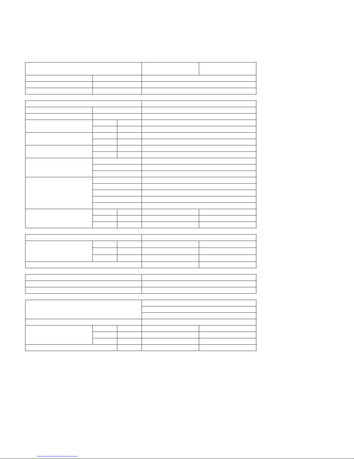
CHAPTER 1. SPECIFICATION
[1] SPECIFICATION............................................ 1-1
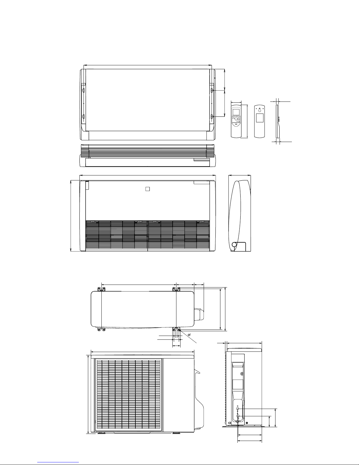
[2] EXTERNAL DIMENSION............................... 1-2
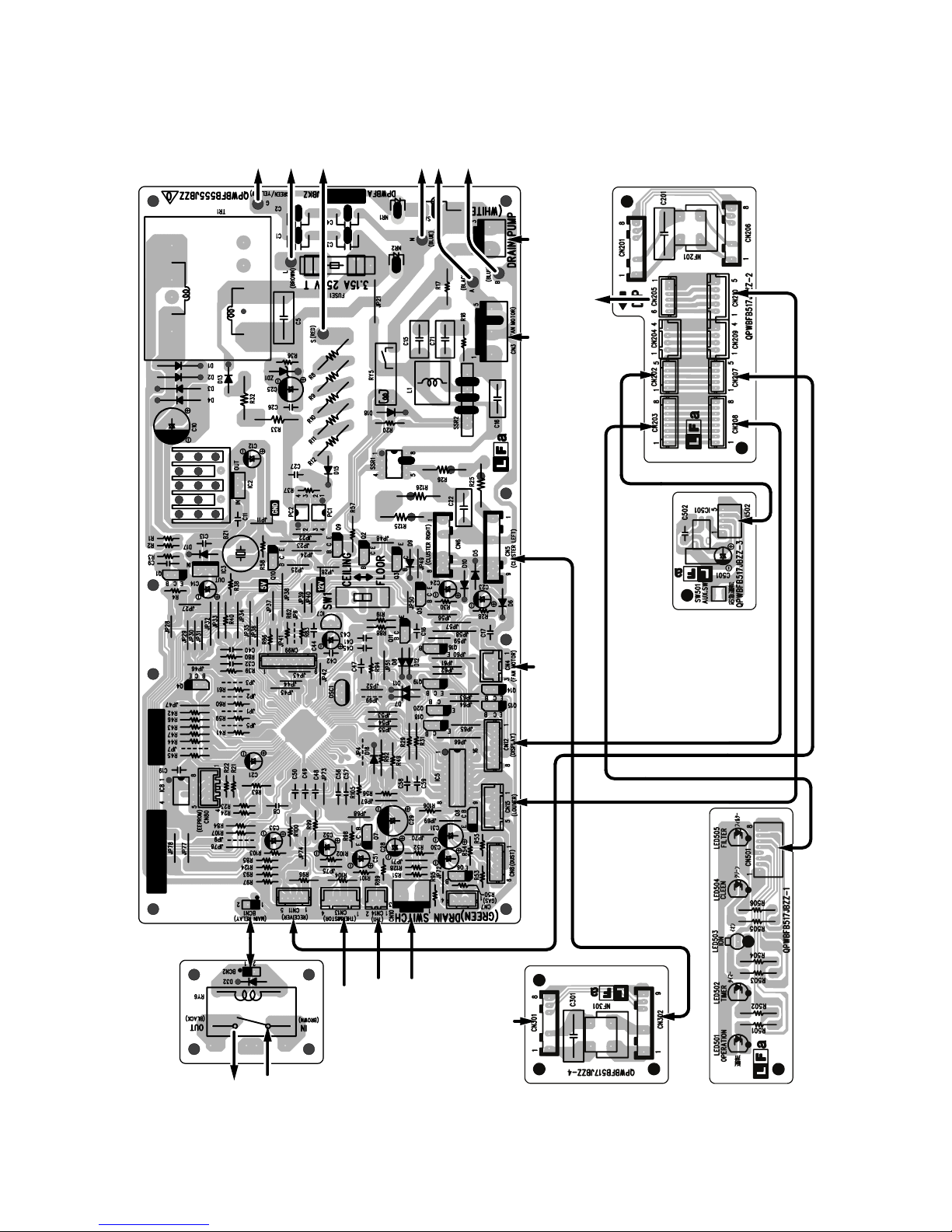
[3] WIRING DIAGRM .......................................... 1-4
[4] ELECTRICAL PARTS .................................... 1-4
CHAPTER 2. EXPLANATION OF CIRCUIT AND OP-
ERATION
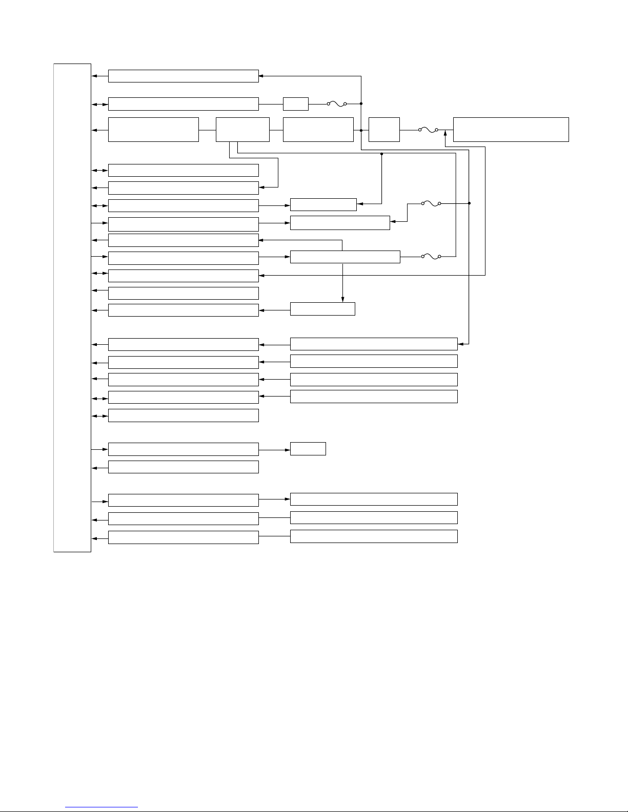
[1] BLOCK DIAGRAMS....................................... 2-1
[2] MICROCOMPUTER CONTROL SYSTEM........ 2-3
[3] FUNCTION..................................................... 2-7
CHAPTER 3. TROUBLESHOOTING
[1] TROUBLESHOOTING GUIDE....................... 3-1
[2] THERMISTOR TEMPERATURE CHAR-
ACTERISTICS ............................................... 3-5
[3] HOW TO OPERATE THE OUTDOOR
UNIT INDEPENDENTLY................................ 3-5
CHAPTER 4. REFRIGERATION CYCLE
[1] FLOW FOR REFRIGERANT.........................4-1
[2] STANDARD CONDITION ..............................4-1
[3] TEMPERATURE AT EACH PART AND
PRESSURE IN 3-WAY VALVE ......................4-1
[4] PERFORMANCE CURVES...........................4-1
CHAPTER 5. DISASSEMBLING PROCEDURE
[1] DISASSEMBLY OF INDOOR UNIT...............5-1
[2] DISASSEMBLY OF OUTDOOR UNIT.........5-13
Parts Guide
TopPage
CONTENTS
SPLIT TYPE
ROOM AIR CONDITIONERS
OUTDOOR UNIT
AE-X12FR-N
In the interests of user-safety (Required by safety regulations in some
countries) the set should be restored to its original condition and only
parts identical to those specified should be used.
INDOOR UNIT
GS-XP12HR-N
CEILING TYPE
FLOOR TYPE
MODELS