IVT 12PHR-N User manual

SERVICE MANUAL
12PHR-N
SPLIT TYPE
AIR TO AIR HEAT PUMP
MODEL
CONTENTS
CHAPTER 1. PRODUCT SPECIFICATION
[1] SPECIFICATION............................................ 1-1
[2] EXTERNAL DIMENSION............................... 1-2
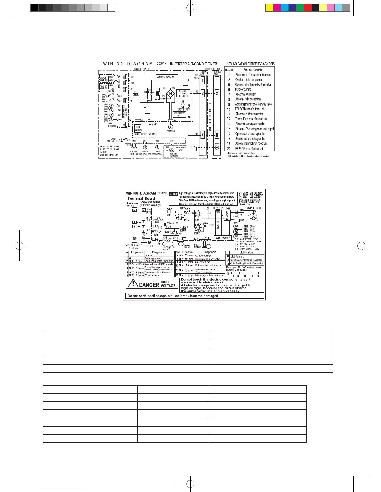
[3] WIRING DIAGRAM......................................... 1-3
[4] ELECTRICAL PARTS..................................... 1-4
CHAPTER 2. EXPLANATION OF CIRCUIT AND
OPERATION
[1] BLOCK DIAGRAMS....................................... 2-1
[2] MICROCOMPUTER CONTROL SYSTEM.... 2-3
[3] FUNCTION..................................................... 2-8
CHAPTER 3. FUNCTION AND OPERATION OF
PROTECTIVE PROCEDURES
[1] PROTECTION DEVICE FUNCTIONS AND OPER-
ATIONS................................................ 3-1
[2] AIR CONDITIONER OPERATION IN THERMIS-
TOR ERROR........................................... 3-2
[3] THERMISTOR TEMPERATURE CHARACTERIST-
ICS............................................................ 3-4
[4] HOW TO OPERATE THE OUTDOOR UNIT INDE-
PENDENTLY.......................................... 3-6
[5] GENERAL TROUBLESHOOTING CHART.... 3-6
[6]
MALFUNCTION (PARTS) CHECK METHOD
....... 3-7
[7] OUTDOOR UNIT CHECK METHOD.............. 3-9
[8] SELF-DIAGNOSIS FUNCTION..................... 3-11
[9] CHART FOR READING SELF-DIAGNOSIS RES-
ULT........................................................ 3-1
CHAPTER 4. REFRIGERATION CYCLE
[1] SCHEMATIC DIAGRAM................................ 4-1
[2] PERFORMANCE CURVES............................ 4-1
CHAPTER 5. DISASSEMBLING PROCEDURE
[1] INDOOR UNIT................................................ 5-1
[2] DISASSEMBLY OF OUTDOOR UNIT............ 5-5
CHAPTER 6. OPERATION MANUAL
CHAPTER 7. INSTALLATION MANUAL
Parts Guide
Parts marked with " !" are important for maintaining the safety of the set. Be sure to replace these parts with specied ones for maintaining the safety
and performance of the set.
This document has been published to be used for
after sales service only.
The contents are subject to change without notice.
12PHR-N
The interests of user-safety(Required by safety regulations in
some countries)the set should be restored to its original condition
and only parts identical to those specied should be used.
S530612XPHRN/C
12PHR-N_S530612PHRN.indd 1 2013/8/7 15:41:57

12PHR-N_S530612PHRN.indd 2 2013/8/7 15:41:57

1-1
12PHR-N
CHAPTER 1. PRODUCT SPECIFICATION
[1] SPECIFICATION
ITEMS MODEL INDOOR UNIT OUTDOOR UNIT
12PHR-N
Rated cooling capacity (Min. – Max.) kW 3.5 (0.9 - 4.0)
Rated heating capacity (Min. – Max.) kW 4.6 (0.9 - 6.5)
Moisture removal Liters/h 1.2
Phase Single
Rated frequency Hz 50
Rated voltage V 230
Rated current ☆
(Min. – Max.) Cool A 4.2 (0.9 - 5.7)
Heat A 5.0 (0.8 - 8.0)
Rated input ☆(Min -
Max.)
Cool
W 920 (200 - 1250)
Heat
W 1060 (160 - 1700)
Power factor ☆Cool % 95
Heat % 92
Maximum operating current A 9.6
Compressor Type Twin Rotary
Model GMCC DA115S1B-27ZF
Oil Charge ESTER OIL VG74 450cc
Refrigerant system Evaporator Louvre Fin and Grooved tube type
Condenser Corrugate Fin and Grooved tube type
Control Expansion valve
Refrigerant (R410A) 1180 g
De-lce system Micro computer controled reversed systems
Noise level(at cooling) High dB(A) 40 47
Low dB(A) - -
Soft dB(A) 27 -
Drive Direct drive
Air ow quantity(at cooling) High m3/min. 9.3 32.2
Low m3/min. 7.6 -
Soft m3/min. 5.2 -
Fan Cross ow fan Propeller fan
Refrigerant coupling Flare type
Refrigerant tube size Gas,Liquid 3/8” ( Φ 9.53 mm), 1/4” ( Φ 6.35 mm)
Drain piping mm O.D. Φ16
Others
Safety device Compressor:Themistor
Fan motors :Inherent themistor
Fuse, Micro computer control
Air lters Polypropylene net (Washable)
Net dimensions Width mm 798 780
Height mm 260 540
Depth mm 290 265
Net weight kg 15 39
NOTE: The conditions of ( ☆) marked items are based om ‘EN14511‘.
12PHR-N
12PHR-N_S530612PHRN.indd 1 2013/8/7 15:41:57

1-2
12PHR-N
[2] EXTERNAL DIMENSION
1. Indoor unit
2. Outdoor unit
Unit
798
260
290
22.0
58 18.5
175
INVERTERAIR CONDITIONER
265
780
540
14
167.5
165
540
299
72
58
37.5
12
4.5
324
135
81
136
12PHR-N_S530612PHRN.indd 2 2013/8/7 15:41:58

1-3
12PHR-N
1. Indoor unit
[3] WIRING DIAGRAM
2 Outdoor Unit
[4] ELECTRICAL PARTS
1. Indoor unit
DESCRIPTION MODEL REMARKS
Fan motor MLB395 DC Motor
Fan motor capacitor - -
Transformer - -
Fu 1 - QFS-GA078JBZZ (250V, 3.15A)
2 Outdoor Unit
DESCRIPTION MODEL REMARKS
Compressor DA115S1B-27FZ DC Motor
Fan motor ARW8403SH DC Motor
Fu 3 - QFS-GA077JBZZ(250V, 2A)
Fu 2 - QFS-GA078JBZZ(250V, 3.15A)
FU1 QFS-CA001JBZZ(250V,20A)
FU5 QFS-CA002JBZZ(250V,15A)
12PHR-N_S530612PHRN.indd 3 2013/8/7 15:41:59

12PHR-N_S530612PHRN.indd 4 2013/8/7 15:41:59

2-1
12PHR-N
CHAPTER 2. EXPLANATION OF CIRCUIT AND OPERATION
[1] BLOCK DIAGRAMS
1. Indoor unit
CPU
DC power supply circuit Rectication circuit AC Power
Fan motor PWM control circuit Indoor fan motor
Rotation pulse input circuit Fan motor pulse detect
AC clock circuit
Remote controller signal reception circuit Wireless remote control operation
Buzzer driver circuit Audible operation conrmation
CPU reset circuit
CPU oscillator circuit
Room temp detect circuit Room temp. thermistor
Heat exchange pipe themo circuit Heat exchanger pipe thermistor
EEPROM Louvre angle,fan speed
Select circuit Heat only, Model select
Serial I/O circuit Indoor/Outdoor control signal I/O Unit-unit wiring
(AC power and
Auto restart circuit serial signals)
Test run circuit Test run (forced operation)
Auxiliary mode Auxiliary mode button ON/OFF
Power on circuit Selfdiagnostics,fault diagnosis
Cluster generator drive circuit Cluster generator
Louver motor drive circuit(Horizontal) How direction control(Horizontal louver
motor)
Louver motor drive circuit(Vertical, right) How direction control(Vertical louver
motor,right)
Louver motor drive circuit(Vertical,left) How direction contorl(Vertical louver
motor,left)
LED Drive circuit LED display
3.15A
Fuse
12PHR-N_S530612PHRN.indd 1 2013/8/7 15:41:59

2-2
12PHR-N
CPU
AC clock circuit
Pulse amplitude modulation circuit IGBT
Power supply circuit Smoothing
circuit Power factor
converter circuit Filter
circuit Unit-unit wiring (AC
powewr and serial
signals)
CPU oscillator circuit
DC overvoltage detection circuit
Outdoor fan drive circuit Outdoor fan
4-way walve relay drive circuit 4-way valve
DC overcurrent detection circuit
Power transistor module drive circuit Power transistor module
Serial I/O circuit
CPU reset circuit
Position detection circuit Compressor
AC overcurrent detection circuit Current transformer
Compressor thermo circuit Compressor thermistor
Heat exchanger pipe thermistor circuit Heat exchanger pipe thermistor
Outdoor temp thermo circuit Outdoor temperature thermistor
EEPROM
LED drive circuit LED
Test mode circuit
Expansion valve drive circuit Expansion valve
Suction temp,thermo,circuit Suction pipe themistor
2-way walve temp,thermo,circuit 2-way valve themistor
Terminal board,Terminal fuse,circuit Terminal board,Terminal fuse
Select Circuit MAX f, Winter Cool
20A
protecition
15A
protecition
2. Outdoor unit
3.15A
protecition
12PHR-N_S530612PHRN.indd 2 2013/8/7 15:41:59

2-3
12PHR-N
[2] MICROCOMPUTER CONTROL SYSTEM
1. Indoor unit
1.1. Electronic control circuit diagram
LED
301
R318
180 1W
FULL
POWER
OUTDOOR
TEMP
LED
304
LED
302
LED
303
R317
360
1W
R316
100
1W
R315
100
1W
RED
YELLOW
GREEN
SG301
OPERATION
TIMER
GREEN
1W 560
f2
b2
COM2
COM1
12
13
15 14 3 2 1 16 4
a1 b1 c1 d1 e1 f1 g1
g2
g1
f1
e2
e1
d2
d1
c2
c1
b1
a2
a1
R304
R305
R306
R307
R308
R309
R310
1W 560
1
2
3
4
5
6
7
8
9
10
g2
f2e2d2c2b2a2
811567910
BCN301
1W 180
1W 180
1W 560
1W 180
1W 180
R128
1K
TERMINAL
BOARD 3P
DC
FAN
MOTOR
AUTO
RESTART
SELECT
0.01uF
250Vx2
275V 0.1uF
C12A
C12B 275V 0.1uF
NC
NC
NC
CLUSTER
BCN602
0.1uF
47uF
50V 1000p
10.0KF
47K
25V
10V
100uF
25V
47K
CN90
1000p
0.1uF
0.1uF
0.1uF
0.1uF
0.1uF
0.1uF
0.1uF
0.1uF
0.1uF
1uF
P83
P82
P81
P80
P05
P06
P70
P71
P72
P73
P74
P75
P76
P77
P67
P66
P65
P64
P31
P63
P62
P61
P60
VDD1
1
2
3
4
5
6
7
8
9
10
11
12
13
14
15
16
17
18
19
20
21
22
23
24
25
26
27
28
29
30
80
79
78
77
76
75
74
73
72
71
70
69
68
67
66
65
P140
P141
P142
P143
P144
P145
64
63
62
61
60
59
58
57
56
55
54
53
52
51
P00
P01
P02
P03
P04
P131
P130
P20
P21
P22
P23
P24
P25
P26
P27
P150
P151
P152
P153
P154
P155
P156
P157
AVSS
VSS1
P30
P87
P86
P85
P84
0.01uF
25V
25V
25V
25V
25V
0.1uF
0.01uF
0.01uF
NC
0.1uF
100uF
10V
4.7K
4.7K
1K
R93
100K
C90
R90
7.5K
4.7K
4.7K
10K
10K
6.8KF
0.1u
50V
100u
35V
25V 0.1u
1M
1/4W
3.3K
910x2
HEAT ONLY
47K
4.7Kx2
POWER
MODEL
BZ1
1/4W
1.8K
KRC108S
KRC108S
NF1
D1N60
11K 2W
4.7K
56K
TEST
4.7K
4.7K
CLUSTER
4.7K
4.7K
6.8KF
3.3K
3.3K
6.8K
56K
16V47uF
10K
6.8K
R6
R7 100K
R8
R17
R19
R18
R29
R31
R32
R34
R37
R36
R71
R76
R77
R78
R80
R81
R86
R88
R95
R96
R100
R101
R108
R109
R110
R111
R112
R114 10KF
D2
R105
R107
ZD1 HZ24-2
C1 35V100uF
C2 35V0.047uF
C3 50V0.01uF
C15
C16
C17
C18
C41
C42
C43
C44
C45
C46
C58
C59
C62
Q13
Q14
Q15
47K
JP8
JP9
JPW
R118
R119
R120
R40
DB1
D2SBA60
1/2W 1MX2
1K
1K
R85
R84
R41
1/2W 1M
C12 275V 0.1uF
NR1
R27 R26
C5 0.01u
250V
R9
Q11
KRC106S
R97
4.7K
25V
0.1uF
C13
R38
100K
R39
16V
C301
C302
R83
10K
D4
D1N60
39K
R28
1/2W
200K 1/2W
200K
R94
1K
C61
0.1uF
KRC108S
1/4W
R302
R303
LED310
3.6Kx2
R121
10K
25V
4.7uF
C60
R11 R10
2.7K
KID65004AF
NC
0.1uF
1000pF
C65
C66
50V 1000p
0.1uF
0.1uF
25V
25V
47K
C402
C401
25V
16V
KID65004AF KID65004AF
25V 0.1uF
47uF
KID65004AF
KID65004AF
KID65783AF
C67
R116
10K
R127
4.7K
4.7K
47K
JP1
47K R125
KID65004AF
10KF
2W
11K
JP2
NC
NC
CN1
21
64
4
5
11
OSC1
8MHz
5V
10K
9
50V
50V
10V
P110
P50
AVR1
AVR0
P111
P51
P52
P53
P54
P55
P56
P57
P17
P16
P15
P14
P13
P12
P11
P10
50
49
48
47
46
45
44
43
42
41
40
39
38
37
36
35
34
33
32
31
99
98
97
96
95
94
93
92
91
90
89
88
87
86
85
84
83
82
81
100
P120
P47
P46
P45
P44
P43
P42
P41
P40
REST
P124
P123
FLMD
X2
X1
REGC
VSS
VSS0
VDD
VDD0
25V
25V
25V
25V
25V
50V
50V
NC
25V
NC
106S
KRC
4
3
1
2
R92
470
5.1K
R91
HAJP
12V
KIA7815
5V
5V 1K
5V
5V
12V
SW401
SAFETY SW
0.01uF
50V
2
1
PC81716NIP
1Vs
Vcc
2
7Vm
GND
5
3PG
1
1
23
4
4
D1N60
2
N
1
2W
10K
1
2
3
4
5
GND
RESET
TOOL0
FLMD0
1
2
3
680
4
PC817XP3
3
1
32
PC817XP3
4
41
28.2K
680
TH1
PIPE TEMP
TH2
R33
R35
R57
R70
R73
R79
R98
R99
R102
R113
R117
D1
ROOM TEMP
IC1
1K
1K
1K
R106
R104
PC4
PC5
PC6
PC7
CN3
C14
C40
C47
C48
C49
C50
C51
C52
C53
C54
C55
C56
Q2
IC13
IC5
10K
KRA224S
R63
8
CN1
NTC1
10D
SSR1
PR32MA11NXPF
R16
R1 3.3K
3.15A-250VFU1
TOOL1
VDD
5V
2M
R74
R75
1K
9
889
IC9
Q10
12V
IC11
CN18
IC12
12V
R82
10K
1
2
PC817XP3
4
3
PC1
PC817XP3
SERIAL SIGNAL CIRCUIT
PC853HXP
32
PC2
+
R301 IC301
5V
CN17
CN10
47
BCN10
CN11
BCN302
PC
37
28
19
10
6
12
8
10
9
8
7
6
5
4
3
2
1
1
3
4
5
6
7
8
7
6
5
4
3
1
8
12345678
9
8
IC7
R122
R124
R123
10K
10K
10K
6
TXD0
RXD0
54321
BLUE
S
C
B
A
5V
2
2
8
7
6
5
4
3
2
1
1
2
3
4
5
6
7
8
9
10
8
6
1
2
3
11
77
C68
50V
PANEL
SW1
SW2
PANEL
1
2
5V
2
3
4
1
2
3
4
1
47 IC401
R401
+
987654321 54321
LOUVERMH
THERMISTOR
THERMISTOR
IC8
6
CN13 CN14 CN15 CN16
BCN401
CN15
R134
R132
R135
R133
5V
BR
BK
WH
RD
1K
1K
13
9 9
5V
D18
55
6
5
4
3
2
1
CN17
FLASH
11
9
10
5V
10
9
11
2
1
2
1
2
1
CN608
CN609
BCN604
10
9
8
7
6
5
4
3
2
1
5V
13
11
12
10
9
8
7
12V
5V
BCN602
BCN601 CN601
CN602
CN603
CN19
LOUVER M
V L LOUVER M
V R
12345
IC14
9
8
12345678
987654321
CN15
CN14
6
6
54321
HANGMR
HANGML
54321
12345678987654
321
12345
PANELMLPANELMR
1 2 345
BCN603 BCN604
CN604 CN605 CN606 CN607
4.3KF
R129
10K
1W 100K
BLUE
R137 680
EC7
C8
C6
G(Y)
10KF
Q3
KRA106S
R51
2.7K
R52
1.5K
R89
2.2M
R72
6.8K
R61
3.3K
R64
3.3K
R136
56K
IC3
KIA431
R54
10KF
R49
220
C30
220uF
10V
C23
10uF
16V
C29
1000uF
25V PC8
PC817x3
R43
47
R42
120K
1/2W
C21
1000pF
1KV
D10
RU2CV1
D5
D1FL20U R45
3.3
C19
100uF
50V
C24
47uF
16V
D8
D1FL20U
D7
S3L20U
ZD3
HZ27-2
C20
120uF
450V
R48
100K
C31
0.1uF 50V
R50
100K
R87
1.5M
PC817XP3
19V
R53 10KF
IC2 TOP258PN
C22 0.1uF 50V
R46
12V
PC8
CONTROL
4
2
1
M
C
DS
S
S
S
8
7
6
5
5V
11
13
7
8
5
15
14
12
10
9
4
3
2
TR1
R44 10
220
16
6
C25 0.01uF 50V
12V
275V
0.1uF
12PHR-N_S530612PHRN.indd 3 2013/8/7 15:42:00

2-4
12PHR-N
LED
301
R318
180 1W
FULL
POWER
OUTDOOR
TEMP
LED
304
LED
302
LED
303
R317
360
1W
R316
100
1W
R315
100
1W
RED
YELLOW
GREEN
SG301
OPERATION
TIMER
GREEN
1W 620
f2
b2
COM2
COM1
12
13
15 14 3 2 1 16 4
a1 b1 c1 d1 e1 f1 g1
g2
g1
f1
e2
e1
d2
d1
c2
c1
b1
a2
a1
R304
R305
R306
R307
R308
R309
R310
1W 620
1
2
3
4
5
6
7
8
9
10
g2
f2e2d2c2b2a2
811567910
BCN301
1W 220
1W 220
1W 620
1W 220
1W 220
0.1uF
47uF
16V
C301
C302
1/4W
R302
R303
LED310
7.5Kx2
C402
C401
25V
16V
25V 0.1uF
47uF
SW401
SAFETY SW
CN18
+
R301 IC301
CN17
47
BCN302
PC
37
28
19
10
6
12
8
10
9
8
7
6
5
4
3
2
1 1
2
3
4
5
6
7
8
9
10
8
6
1
2
3
11
77
2
3
4
1
2
3
4
1
47 IC401
R401
+
BCN401
13
9 9
55
10
9
8
7
6
5
4
3
2
1
13
11
12
10
9
8
7
12V
5V
BCN602
BCN601 CN601
CN602
CN603
BLUE
1.2. Display circuit diagram
12PHR-N_S530612PHRN.indd 4 2013/8/7 15:42:01

2-5
12PHR-N
1.3. Printed wiring board
12PHR-N_S530612PHRN.indd 5 2013/8/7 15:42:01

2-6
12PHR-N
To main PWB To main PWB To main PWB To main PWB
From panel
SW left From panel
SW right From panel
motor right From hang
motor right
From display
PWB(black) From display
PWB(yellow)
To connectionP WB
For Connection PWB
For Display PWB
From hang
motor left
From receiver
PWB
From panel
motor left
12PHR-N_S530612PHRN.indd 6 2013/8/7 15:42:01

2-7
12PHR-N
2. Outdoor unit
2.1. Electronic control circuit diagram
0.033
12PHR-N_S530612PHRN.indd 7 2013/8/7 15:42:09

2-8
12PHR-N
2.2. Printed wiring board
From 4Way Valve
From Expansion Valve
From Thermistor
From Fan Motor
From Compressor (R)(W)(Orange)
From Compressor
From Compressor (S)(V) (Red)
To Reactor(Gray)
To Terminal Board(1)
(Brown)
To Terminal Board(N)
(Blue)
To Control Box
(Green/Yellow)
To Terminal Board(2)
(Red)
(C)(W)(White)
12PHR-N_S530612PHRN.indd 8 2013/8/7 15:42:10

2-9
12PHR-N
[3] FUNCTION
1. Function
1.1. Restart control
Once the compressor stops operating, it will not restart for 180
seconds to protect the compressor.
Therefore, if the operating compressor is shut down from the
remote control and then turned back on immediately after, the
compressor will restart after a preset delay time.
(The indoor unit will restart operation immediately after the ON
switch is operated on the remote control.)
Compressor operation
ON operation on
remote control
OFF operation on
remote control Compressor ON
Compressor can
turn ON
Compressor ON
Compressor remains OFF
for 180 seconds
1.2. Indoor unit heat exchanger freeze prevention control
If the temperature of the indoor unit heat exchanger remains
below 0°C for 4 consecutive minutes during cooling or
dehumidifying operation, the compressor operation stops
temporarily in order to prevent freezing.
When the temperature of the indoor unit heat exchanger rises to
2°C or higher after about 180 seconds, the compressor restarts
and resumes normal operation.
1.3. Outdoor unit 2-way valve freeze prevention control
If the temperature of the outdoor unit 2-way valve remains below
0°C for 10 consecutive minutes during cooling or dehumidifying
operation, the compressor operation stops temporarily in order to
prevent freezing.
When the temperature of the 2-way valve rises to 10°C or higher
after about 180 seconds, the compressor restarts and resumes
normal operation.
1.4. Indoor unit overheat prevention control
During heating operation, if the temperature of the indoor unit
heat exchanger exceeds the indoor unit heat exchanger overheat
prevention temperature (about 45 to 54°C) which is determined
by the operating frequency and operating status, the operating
frequency is decreased by about 4 to 15 Hz. Then, this operation
is repeated every 60 seconds until the temperature of the
indoor unit heat exchanger drops below the overheat protection
temperature.
Once the temperature of the indoor unit heat exchanger drops
below the overheat protection temperature, the operating
frequency is increased by about 4 to 10 Hz every 60 seconds until
the normal operation condition resumes.
If the temperature of the indoor unit heat exchanger exceeds
the overheat protection temperature for 60 seconds at minimum
operating frequency, the compressor stops operating and then
restarts after about 180 seconds, and the above mentioned
control is repeated.
1.5. Outdoor unit overheat prevention control
During cooling operation, if the temperature of the outdoor
unit heat exchanger exceeds the outdoor unit heat exchanger
overheat prevention temperature (about 55°C), the operating
frequency is decreased by about 4 to 15 Hz. Then, this operation
is repeated every 60 seconds until the temperature of the outdoor
unit heat exchanger drops to about 54°C or lower.
Once the temperature of the outdoor unit heat exchanger drops
to about 54°C or lower, the operating frequency is increased by
about 4 to 10 Hz every 60 seconds until the normal operation
condition resumes.
If the temperature of the outdoor unit heat exchanger exceeds
the outdoor unit heat exchanger overheat protection temperature
for (120 sec: outdoor temperature ≥ 40°C · 60 sec : outdoor
temperature < 40°C) at minimum operating frequency, the
compressor stops operating and then restarts after about 180
seconds, and the abovementioned control is repeated.
1.6. Compressor overheat prevention control
If the temperature of the compressor exceeds the compressor
overheat prevention temperature (110°C), the operation frequency
is decreased by about 4 to 10 Hz. Then, this operation is repeated
every 60 seconds until the temperature of the compressor drops
below the overheat protection temperature (100°C).
Once the temperature of the compressor drops below the
overheat protection temperature, the operating frequency is
increased by about 4 to 10 Hz every 60 seconds until the normal
operation condition resumes.
If the temperature of the compressor exceeds the overheat
protection temperature (for 120 seconds in cooling operation or
60 seconds in heating operation) at minimum operating frequency,
the compressor stops operating and then restarts after about 180
seconds, and the above mentioned control is repeated.
1.7. Startup control
When the air to air heat pump starts in the cooling or heating
mode, if the room temperature is 2°C higher than the set
temperature (in cooling operation) or 3.5°C lower (in heating
operation), the air to air heat pump operates with the operating
frequency at maximum. Then, when the set temperature is
reached, the air to air heat pump operates at the operating
frequency determined by fuzzy logic calculation, then enters the
normal control mode after a while.
1.8. Peak control
If the current owing in the air to air heat pump exceeds the peak
control current the operation frequency is decreased until the
current value drops below the peak control current regardless of
the frequency control demand issued from the indoor unit based
on the room temperature.
1.9. Outdoor unit fan delay control
The compressor stops immediately after cooling, dehumidifying or
heating operation is shut down, but the outdoor unit fan continues
operation for 50 seconds before it stops.
1.10. Defrosting
1.10.1 Reverse defrosting
The defrost operation starts when the compressor operating time
exceeds 20 minutes during heating operation, as shown below,
and the outside air temperature and the outdoor unit heat
exchanger temperature meet certain conditions. When the defrost
operation starts, the indoor unit fan stops. The defrost operation
stops when the outdoor unit heat exchanger temperature rises to
about 13°C or higher or the defrosting time exceeds 10 minutes.
20 min or more 6 min or more 6 min or more
Defrosting
Max. 10 min Defrosting
Max. 10 min
Start of
heating
operation
12PHR-N_S530612PHRN.indd 9 2013/8/7 15:42:10

2-10
12PHR-N
1.11. ON timer
The ON timer can be activated by pressing the ON timer button.
When the ON timer is activated, the operation start time is
adjusted based on fuzzy logic calculations 1 hour before the set
time so that the room temperature reaches the set temperature at
the set time.
1.12. OFF timer
The OFF timer can be activated by pressing the OFF timer button.
When the OFF timer is set, the operation stops after the set time.
When this timer is set, the compressor operating frequency lowers
for quieter operation, and the room temperature is gradually
varied after one hour (reduced 1°C three times (max. 3°C) in
heating, or increased 0.3°C three times (max. 1°C) in cooling or
dehumidifying operation) so that the room temperature remains
suitable for comfortable sleeping.
Heating operation
Set temperature
Activation of
OFF timer 1 hour
later Max.
1.5 hours
later
Max.
2 hours
later
Timer setting
reached
1 hour
later Max.
1.5 hours
later
Max.
2 hours
later
Timer setting
reached
Activation of
OFF timer
Set temperature
-1 C
-1 C
-1 C
0 3 C 0.3 C 0.3 C
Cooling/dehumidifying operation
1.13. Power ON start
If a jumper cable is inserted in the location marked with HAJP
on the indoor unit control printed circuit board (control PCB),
connecting the power cord to an AC outlet starts the air to air
heat pump in either cooling or heating mode, which is determined
automatically by the room temperature sensor.
When a circuit breaker is used to control the ON/OFF operation,
please insert a jumper as described above.
1.14. Self-diagnostic malfunction code display
1.14.1 Indoor unit
1) When a malfunction is conrmed, a ashing malfunction code
number is displayed to indicate the type of malfunction.
When the air to air heat pump is in non-operating condition,
holding down AUX button for more than 5 seconds activates the
malfunction code display function.
The operation continues only in the case of a serial open-circuit.
In the case of a serial short-circuit, the air to air heat pump
continues operating without a malfunction code display.
2) The content of self-diagnosis (malfunction mode) is indicated
by a ashing number.
(For details, refer to the troubleshooting section.)
1.14.2 Outdoor unit
If a malfunction occurs, LED1 on the outdoor unit flashes in
0.2-second intervals as shown below.
1 sec 1 sec 0.5 sec
ON
OFF
(Example) Compressor high temperature abnormality
1.15. Information about auto mode
In the AUTO mode, the temperature setting and mode are
automatically selected according to the room temperature and
outdoor temperature when the unit is turned on.
Modes and Temperature Settings
the figures in ( ) are temperature settings
During operation, if the outdoor temperature changes, the
temperature settings will automatically slide as shown in the chart.
12PHR-N_S530612PHRN.indd 10 2013/8/7 15:42:11

2-11
12PHR-N
1
Press the HORIZONTAL AIR FLOW button
to set the desired air ow direction.
CAUTION:
Never attempt to adjust the open panel and the louvres
manually.
• Manual adjustment of the open panel and the louvres can
cause the unit to malfunction.
1
0.6
O
C
Set temperature
Hot keep zone
1
COOL mode
The open panel will be set obliquely downward for 10
minutes, and then shift to obliquely upward to deliver
cool air to the ceiling.
HEAT mode
The open panel will be set obliquely backward when
outlet air temperature is low, and then shift to obliquely
downward when outlet air becomes warm.
DRY mode
The open panel will be set obliquely upward.
10 minutes later
1
Press the VERTICAL AIR FLOW button
to set the desired air ow direction.
AUTO mode
AUTO
obliquely downward
HEAT mode
AUTO
obliquely downward
obliquely upward downward
COOL/DRY mode
AUTO
obliquely upward obliquely downward
When outlet air
temperature is low When outlet air
becomes warm
1.16. Adjusting the air ow direction
1.16.1 Vertical air ow direction 1.16.2 Horizontal air ow direction
TIPS ABOUT AIR FLOW DIRECTION “AUTO“
Heating operation Fanoperation
24
O
COutsideair temperature
1.17. Difference of operation in Auto and Manual modes
In the Auto mode, the temperature setting is automatically determined based on the outside air temperature. In addition, the air to air
heat pump operation differs from the operation in the Manual mode as explained below.
1.17.1 Difference relating to set temperature
Auto mode Manual mode
Cooling Heating Dehumidifying Cooling Heating Dehumidifying
Temperature
setting method Automatic temperature setting based on outside
air temperature.Can be changed within ±2°C using
remote control.
Can be changed
between 18 and
32°C using remote
control
Can be changed
between 18
and 32°C using
remote control.
Automatic setting.
Can be changed
within ±2°C.
12PHR-N_S530612PHRN.indd 11 2013/8/7 15:42:12

2-12
12PHR-N
1.18. Dehumidifying operation control
If the room temperature is 26°C or higher when dehumidifying
operation starts, the dehumidifying operation provides a low
cooling effect in accordance with the room temperature setting
automatically determined based on the outside air operation.
(The setting value is the same as the set temperature for cooling
operation in the auto mode.)
If the room temperature is lower than 26°C when dehumidifying
operation starts, the dehumidifying operation minimizes the
lowering of the room temperature.
1.19. Self Clean operation
Heating or Fan operation and Cluster operation are performed
simultaneously.
Whether start Heating or Fan operation is determined by the
outside air temperature at 3 minutes after the start of self
cleaning.
The operation stops after 40 minutes. (The air to air heat pump
shows the remaining minutes: 40 → 39 → 38 ... 3 → 2 → 1)
1.20. Plasmacluster Ion function
The Plasmacluster lon generator inside the air conditioner will
release positive and negative plasmacluster ions into the room.
Approximately the same numbers of positive and negative ions
released into the air will reduce some airborne mold.
During operation, press the PLASMACLUSTER button.
• The remote control will display “ “.
• The blue PLASMACLUSTER lamp on the unit will light up.
TO CANCEL
Press the PLASMACLUSTER button again.
• The PLASMACLUSTER lamp on the unit will turn off.
NOTE:
• Use of the PLASMACLUSTER operation will be
memorized, and it will be activated the next time you turn on
the air conditioner.
• To turn off the PLASMACLUSTER lamp, press the
DISPLAY button.
• To perform the PLASMACLUSTER operation in FAN only
mode, press the PLASMACLUSTER button while the unit is
not operating. The mode symbol of the remote control will go
off and the fan speed can not be set toAUTO.
1.21. Winter cool
Cooling operation is available during the winter season by the
built in winter cool function.
Lower limit of outdoor temperature range is -10°C DB.
When the outside air temperature is low, the outdoor unit fan
operates at slower speed.
NOTE:
Built-in protect device may work when outdoor temperature
falls below 21°C DB., depending on conditions.
1.22. 10°C OPERATION
Heating operation with 10°C set temperature will be performed.
1) Press the MODE button of Remote controller and select HEAT
mode.
2) Press the ON / OFF button to start HEAT operation.
3) Press the 10°C button.
• The remote control will display 10°C.
TO CANCEL
Press the 10°C button again.
• 10°C operation will also be cancelled when the operation
mode is changed, or when the unit is turned off.
NOTE:
• 10°C operation will not be available with heating operation
automatically selected by AUTO mode.
1.23. Auto restart
When power failure occures, after power is recovered, the unit will
automatically restart in the same setting which were active before
the power failure.
1.23.1 Operating mode (Cool, Heat, Dry)
• Temperature adjustment (within 2°C range)
automatic operation
• Temperature setting
• Fan setting
• Air ow direction
• Power ON/OFF
• Automatic operation mode setting
• Swing louvre
• Plasmacluster mode
1.23.2 Setting not memorized
• Timer setting
• Full power setting
• Self clean
1.23.3 Disabling auto restart function
By removing (cutting) jumper 8 (JP8) on the printed circuit board
(PCB), the auto restart function can be disabled.
1.24 Heat only mode
Heating operation Fanoperation
24
O
C
Outsideair temperature
Cut the JPW jumper when you want heat only mode.
cool/heat mode JPW connected
heat only mode JPW cut
JPW
12PHR-N_S530612PHRN.indd 12 2013/8/7 15:42:12

2-13
12PHR-N
2. Explanation of Plasmacluster circuit
The cluster unit generates cluster ions, which are circulated throughout the room by the air ow created by the blower fan(indoor unit
fan) in the air to air heat pump unit.
1)When microcomputer output turns "H", the Q11 output changes to "Lo", turning ON the cluster unit for the generation of cluster ions
(positive and negative ions).
5
1
12V
SSR1 R16
R18
IC13
AC230V
Microcomputer output
4
1
Cluster unit
R19
R17
6
2
4
1
C5
3. Outline of PAM circuit
3.1. PAM (Pulse Amplitude Modulation)
The PAM circuit varies the compressor drive voltage and controls the rotation speed of the compressor.
The IGBT shown in the block diagram charges the energy (electromotive force) generated by the reactor to the electrolytic capacitor for
the inverter by turning ON and OFF.
PAM drive circuit block diagram
Reactor L5
[PAM drive circuit]
+
Microcomputer (IC1)
AC
230V
Compressor
Noise
filter
AC clock
detection
circuit
DB1
IPM
DB2
Compressor
position
detector
IGBT
drive
circuit
IGBT
Overvoltage
detection
circuit
When the IGBT is ON, an electric current ows to the IGBT via the reactor (L1) and diode bridge (DB2).
When the IGBT turns OFF, the energy stored while the IGBT was ON is charged to the voltage capacitor via the diode bridge (DB1).
As such, by varying the ON/OFF duty of the IGBT, the output voltage is varied.
Stored energy Reactor
L5
DB1
DB2
IGBT
IGBT ON
IGBT OFF
12PHR-N_S530612PHRN.indd 13 2013/8/7 15:42:12

2-14
12PHR-N
3.2. High power factor control circuit
This circuit brings the operating current waveform closer to the waveform of commercial power supply voltage to maintain a high power
factor. Because of the capacitor input, when the PAM circuit is OFF, the phase of the current waveform deviates from the voltage wave-
form as shown below.
To prevent this deviation, a current is supplied during the periods indicated by "O" in the diagram. To determine the length of period
to supply a current, the zero-cross timing of the AC input voltage is input to the microcomputer via the clock circuit. The power source
frequency is also determined at the same time.
The IGBT turns ON after the time length determined by the zero-cross point to supply a current to the IGBT via the reactor. This brings
the current waveform closer to the voltage waveform in phase.
As described above, the ON/OFF operation of the IGBT controls the increase/decrease of the compressor power supply voltage (DC
voltage) to improve the compressor efciency and maintain a high power factor by keeping the current phase closer to that of the sup-
ply voltage.
AC voltage waveform
AC voltage and current waveform when PAM is ON
AC current waveform
IGBT ON period
Zero-cross detection
AC voltage waveform
AC current waveform
AC voltage and current waveforms when PAM is OFF
3.2.1 Detailed explanation of PAM drive circuit sequence
AC voltage waveform
Clock
IGBT ON
A
B C
A
B
C
50Hz
1.2mS
1.0mS
0.25 2.3mS
3.2.2 AC clock (zero-cross) judgment
• The clock circuit determines the time from one rising point of the clock waveform to the next rising point.
The detected clock waveform is used to judge the power source frequency (50Hz).
• The zero-cross of the AC voltage is judged as the rising of the clock waveform, as shown in the diagram above.
3.2.3 IGBT ON start time (delay time B)
• Based on the zero-cross of the AC voltage, the IGBT turns ON after a delay time set according to the power source frequency.
3.2.4 IGBT ON time (C)
• After the above delay time, the IGBT turns ON to supply a current to the reactor.
• The ON time of the IGBT determines the amount of energy (level of DC voltage rise) supplied to the reactor.
DC voltage level in each operation mode (varies depending on external load conditions)
–Cooling operation --- 220 to 290 V
12PHR-N_S530612PHRN.indd 14 2013/8/7 15:42:13
Other manuals for 12PHR-N
1
Table of contents
Other IVT Air Conditioner manuals