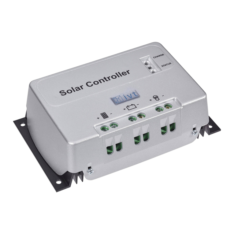
IVT SCplus User manual

Solar Controller SCplus/SCDplus
BEDIENUNGSANLEITUNG Seite 2 – 9
INSTRUCTION MANUAL page 10 – 17
NOTICE D’UTILISATION côté 18 – 25
GEBRUIKSAANWIJZING pagina 26 – 33

2
Sehr geehrte Kundin, sehr geehrter Kunde,
vielen Dank für Ihr entgegengebrachtes Vertrauen. Sie haben ein leistungsstarkes und zuverlässiges Produkt erworben, das Ihnen bei
sachgemä er Handhabung lange Zeit gute Dienste leisten wird.
Bitte lesen Sie diese Bedienungsanleitung sorgfältig und vollständig durch, bevor Sie das Gerät in Betrieb nehmen. Sie erhalten wichtige
Hinweise für einen sicheren Betrieb und für die Wartung des Gerätes.
Lieferumfang
Solar-Controller, Temperatursensor, Anschlussadapter für Spannungssensor, Bedienungsanleitung
Bestimmungsgemäße Verwendung
Die Solarregler der SCplus/SCDplus-Serie wurden zum Laden von Solar-Batterien (Blei-Säure, AGM, GEL) innerhalb eines
Solar-Inselsystems entwickelt. Der Solar-Controller ist auch für das Laden von Lithium-Eisenphosphat-Akkus (LiFePO
₄
) mit integriertem
BMS (Balancing Management System) geeignet.
Der Benutzer muss sicherstellen, dass das Gerät vor Feuchtigkeit und Nässe geschützt wird. Eine andere Verwendung als zuvor
beschrieben, führt zur Beschädigung dieses Produktes, darüber hinaus ist dies mit Gefahren, wie z.B. Kurzschluss, Brand, elektrischer
Schlag etc. verbunden.
Das gesamte Produkt darf nicht geändert bzw. umgebaut werden.
Sicherheitshinweise
Sehr geehrte Kundin, sehr geehrter Kunde,
die folgenden Sicherheits- und Gefahrenhinweise dienen nicht nur um Schut des Gerätes, sondern auch um Schut Ihrer
Gesundheit. Lesen Sie sich bitte die folgenden Punkte aufmerksam durch. Bei Sach- oder Personenschäden, die durch
unsachgemäße Handhabung oder Nichtbeachtung dieser Bedienungsanleitung b w. der hier aufgeführten Sicherheitshinweise
verursacht werden, erlischt die Gewährleistung/Garantie. Für Folgeschäden übernehmen wir keine Haftung!
Allgemein
•Aus Sicherheits- und Zulassungsgründen (CE) ist das eigenmächtige Umbauen und/oder Verändern des Produktes
nicht gestattet.
•Dieses Gerät gehört nicht in Kinderhände! Stellen Sie sicher, dass das Gerät zu jeder Zeit kindersicher betrieben
und gelagert wird.
•Wartungs-, Einstellungs- oder Reparaturarbeiten dürfen nur von einem Fachmann/Fachwerkstatt durchgeführt
werden. Zur Reparatur dürfen nur original Ersatzteile verwendet werden. Die Verwendung abweichender Ersatzteile
kann zu erheblichen Sach- und Personenschäden führen!
•Lassen Sie das Verpackungsmaterial nicht achtlos liegen. Dieses könnte für Kinder zu einem gefährlichen
Spielzeug werden!
•Gehen Sie vorsichtig mit dem Produkt um, durch Stö e, Schläge oder dem Fall aus bereits geringer Höhe wird es
beschädigt. Lassen Sie den Solarladeregler in diesem Fall vor Wiederinbetriebnahme von geschultem
Fachpersonal überprüfen.
•Wenn Sie Beschädigungen feststellen, so darf das Gerät nicht mehr betrieben werden. Bringen Sie es in eine
Fachwerkstatt oder entsorgen Sie es umweltgerecht.
Betrieb
•Das Produkt darf nur in trockener Umgebung betrieben werden. Es darf nicht feucht oder nass werden, andernfalls
besteht die Gefahr eines lebensgefährlichen elektrischen Schlages.
•Der Betrieb unter widrigen Umgebungsbedingungen ist unter allen Umständen zu vermeiden. Widrige
Umgebungsbedingungen sind: Umgebungstemperaturen über 50°C, brennbare Gase, Lösungsmittel, Dämpfe,
Staub, Luftfeuchtigkeit über 80% rel. Luftfeuchte, sowie Nässe.
•Das Gerät darf nicht in der Nähe von entzündlichen Materialien, offenem Feuer oder Gasen betrieben werden. Es
besteht Explosionsgefahr!
•Achten Sie auf ausreichende Belüftung während der Betriebsphase, decken Sie den Solarladeregler und die
angeschlossenen Geräte niemals ab.
•Schützen Sie den Solarladeregler vor elektromagnetischen Feldern sowie Erschütterungen und Vibrationen.
•Schützen Sie den Solarladeregler vor zu hohen Umgebungstemperaturen!
•Vermeiden Sie plötzliche Temperaturunterschiede! Dabei kann es im Solarladeregler zu Kondenswasser-Bildung
kommen! In diesem Fall muss der Solarladeregler vor Inbetriebnahme mindestens eine Stunde an einem gut
belüfteten Ort an die neue Umgebungstemperatur angepasst werden.

3
Batteriehinweise:
Solar-Batterien stellen bei nicht sachgemä em Gebrauch eine gro e Gefahr für Menschen, Tiere und Umwelt dar.
Beachten Sie stets die Sicherheitshinweise des Batterieherstellers!
Solar-Batterien enthalten aggressive ätzende Säuren. Vermeiden Sie Haut- und Augenkontakt mit Flüssigkeiten aus der Batterie!
Zerlegen Sie Solar-Batterien niemals! Ist Säure ins Auge oder auf die Haut gelangt, waschen Sie dieses sofort unter flie endem, kaltem
Wasser aus! Suchen Sie danach sofort einen Arzt auf! Ist Säure auf Ihre Kleidung gelangt, entfernen Sie sofort die kontaminierte
Kleidung und waschen Sie eventuell betroffene Hautstellen unter flie endem, kaltem Wasser gründlich ab.
Anschlüsse und Bedienelemente
1. Sicherung
2. Taster (Pfeil links) (nur SCD lus)
3. Taster (Pfeil rechts) (nur SCD lus)
4. LCD-Display (nur SCD lus)
5. Taster (Pfeil hoch) (nur SCD lus)
6. Taster (Pfeil runter) (nur SCD lus)
7. LED „Status“
8. LED „Load“
9. Anschluss für Temperatursensor
10. +/- Anschluss Lastausgang
11. +/- Anschluss Solar-Batterie
12. +/- Anschluss Solarmodul
13. Anschluss für Spannungssensor
14. „Load“ Taster für Ein- und Ausschalten des
Lastausgangs
15. USB-Anschluss für Konfiguration mit PC
Features
•Automatische Erkennung der Systemspannung (bei 12/24 V)
•Temperaturgesteuerte Laderegelung
•Einstellbarer Tiefentladeschutz mit Vorwarnung
•Modul- und Lastabschaltung im Pluskreis
•Verschiedene Ladeprofile auswählbar (SLA, AGM, GEL, LiFePO4, User)
•Einstellbarer Temperaturkoeffizient
•Programmierbares Ein- und Ausschalten des Lastausganges
•Energiezähler
•Funktionen mit PC-Software einstellbar
•Aufzeichnung und Überwachung mittels PC-Software
Funktionsbeschreibung
Der Solar-Controller arbeitet nach dem Prinzip der pulsweitenmodulierten Serienregelung d.h. das Abregeln an der Ladegrenze wird
durch eine Modulation des Ladestromes aus dem Solarmodul erreicht. Durch den Temperatur-Sensor wird die Ladeendspannung der
Umgebungstemperatur automatisch angepasst.
Für eine optimale Funktionalität stehen umfangreiche Einstellmöglichkeiten zur Verfügung.
Bei den SC-Modellen können die Einstellungen mittels kostenloser Software am PC vorgenommen werden.
Für die Einstellungen der SCD-Modelle kann entweder die kostenlose PC- Software oder die Tasten und das Display des jeweiligen
Gerätes verwendet werden.
Die PC-Software können Sie unter folgender Internetadresse herunterladen: http://www.ivt-hirschau.de/downloads
Montage
Um eine sachgemä e Inbetriebnahme zu gewährleisten, lesen Sie vor Gebrauch unbedingt diese Bedienungsanleitung mit den
Sicherheitshinweisen vollständig und aufmerksam durch.
Wichtiger Hinweis: Bitte beachten Sie beim Anschließen Ihrer Solar-Komponenten unbedingt die richtige Reihenfolge!
•Achten Sie bei der Montage darauf, dass der Solarregler sowie alle weiteren Systemkomponenten für Kinder unzugänglich
angebracht sind. Lebensgefahr!
•Montieren Sie den Solar-Controller nicht unmittelbar über einer Wärmequelle! Achten Sie darauf, dass die Batterie in einem
gut durchlüfteten Raum untergebracht ist! Achten Sie unbedingt auf die richtige Polarität!

4
•Sorgen Sie stets für eine ausreichende Belüftung Ihres Solarreglers. Decken Sie niemals die Lüftungsschlitze des Solarreglers
ab. Betreiben Sie das Gerät nicht in der Nähe von leicht entflammbaren Materialien.
•Beachten Sie, dass in Batterien gro e Energiemengen gespeichert werden. Bei einem Kurzschluss können diese
Energiemengen in kurzer Zeit freigesetzt werden. Folglich kann es am Ort des Kurzschlusses zu gro er Hitzeentwicklung bzw.
zu einem Brand kommen.
Achtung: Alle Komponenten (Solarmodul, Batterie, Verbraucher und Solar-Controller) müssen in Spannung und Stromstärke
aufeinander abgestimmt sein. Überprüfen Sie da u die Angaben auf dem jeweiligen Typenschild. Wenden Sie sich im
Zweifelsfall an Ihren Fachhändler. Achten Sie unbedingt auf die richtige Polarität!
Wichtige Hinweise:
•Bei Verpolung am Lastausgang können Geräte, die selbst nicht abgesichert sind, erstört werden. Die jeweiligen
Verbraucher müssen deshalb individuell abgesichert werden.
•Um einen sicheren Betrieb u gewährleisten, müssen Sie unbedingt darauf achten, dass Sie beim Anschließen der
ein elnen Systemkomponenten die richtige Reihenfolge einhalten.
Anschlussreihenfolge:
1. Anschluss der Batterie
Verbinden Sie die Batterie an den vorgesehenen Schraubklemmen (11) am Solar-Controller. Um den Spannungsabfall gering
und die damit verbundene Kabelerwärmung niedrig zu halten, wird ein entsprechender Kabelquerschnitt empfohlen. Die
Klemmen sind für die Aufnahme bis zu Querschnitten von 16mm² ausgelegt.
•Die erforderlichen Mindestquerschnitte betragen: 1,5 mm² bis 15 A, 4,0 mm² bis 25 A, 10,0 mm² bis 40 A.
•Achten Sie darauf, dass die Zuleitung zwischen Batterie und Solar-Controller vorschriftsmä ig abgesichert ist.
•Batterie und Solar-Controller müssen im gleichen Raum mit geringem Abstand zueinander installiert werden.
2. Anschluss des Solarmoduls
Verbinden Sie das Solarmodul an den entsprechenden Schraubklemmen (12) am Solar-Controller.
3. Anschluss der Last
Verbinden Sie schlie lich die DC-Verbraucher mit dem Lastausgang (10) des Solar-Controllers.
Die Anschlussbelegung kann anhand der Symbole am Solarregler oder aus Abbildung (siehe Anschlüsse- und
Bedienelemente) entnommen werden.
Hinweise:
•Achten Sie beim Anschluss der DC-Verbraucher auf die richtige Polarität!
•Stellen Sie sicher, dass der Lastausgang des Solarreglers ausgeschaltet ist!
LED An eige
Die LED „Status“ (7) gibt Auskunft über den Ladezustand der Batterie:
•aus Laderegler im Standby-Modus; kein Laden der Batterie
•rot blinken Batteriespannung kurz vor unterem Entladelimit (Warnung vor Tiefentladung)
•rot Batteriespannung am Entladelimit; Lastausgang wird abgeschaltet (Tiefentladeschutz)
•grün wiederholend 1x kurz blinken Laden in Stage1-Modus
•grün wiederholend 2x kurz blinken Laden in Stage2-Modus
•grün wiederholend 3x kurz blinken Laden in Stage3-Modus
Die LED „Load“ (8) gibt Auskunft über den Status des Lastausganges:
•Aus Lastausgang aus
•Ein Lastausgang ein
Eine detaillierte Erklärung der Lademodi finden Sie im Diagramm Menü-Beschreibung.
Tiefentladeschut
Solar-Batterien müssen vor Tiefentladung geschützt werden, da es sonst zu irreparablen Schäden kommen kann. Der Solar-Controller
schützt die Batterien zuverlässig vor Tiefentladung indem er bei Erreichen der Entladeschlussspannung die angeschlossene DC-Last
abschaltet. Sobald die Batterien über die Solarzellen ausreichend nachgeladen werden, wird der Lastausgang automatisch in
Abhängigkeit von den Voreinstellungen wieder eingeschaltet.
Überladeschut
Wird die Ladeendspannung erreicht, ist die Batterie noch nicht vollständig geladen. Der Ladestrom wird dann reduziert, damit die
Ladeendspannung nicht überschritten wird. Dieses Verfahren lädt die Batterie schonend und schnell ohne sie zu überladen.
Temperaturkompensation
Der Temperaturfühler sorgt für optimale Anpassung der Ladeendspannung an die Umgebungstemperatur der Batterie. Dafür sollten
Regler und Batterie im gleichen Raum sein.

5
Spannungssensor für Batterie
Stellen Sie über den „Battery sense“-Anschluss (13) mit Hilfe des beigelegten Anschlussadapters eine Verbindung mit den Batteriepolen
her, um eine noch präzisere Funktionsweise des Solarladereglers zu erhalten.
Wechsel der Sicherung
Der Solar-Controller hat für Lade- und Lastausgang eine leicht zugängliche Stecksicherung.
Achtung: Die Sicherung darf nur durch eine des gleichen Typs und mit gleicher Nennstromstärke ersetzt werden!
LCD-An eige (nur bei SCDplus-Modellen)
Wird der Solar-Controller mit der Batterie verbunden läuft für ca. 10 Sekunden die Initialisierung-Phase.
Die Systemspannung wird durch die Sensoren identifiziert und übernommen (Abb. 2).
Während dieser Phase erscheinen im Display folgende Meldungen:
Abb. 1 Abb. 2 Abb. 3
Achtung! Während dieser Initialisierungs-Phase dürfen keine Tasten gedrückt werden!
In der Displayanzeige Abb. 3 werden folgende Daten angezeigt:
•die aktuelle Batteriespannung (U:)
•der aktuelle Ladestrom (C:)
•der aktuelle Laststrom (L:)
•der aktuelle Ladezustand (Balkenanzeige)
Durch Drücken der Taste wechseln Sie durch folgende Displaymeldungen:
Abb. 4 Abb. 5 Abb. 6
In den Displayanzeigen Abb. 4 – Abb. 6 werden folgende Daten angezeigt:
•die Gesamtladung (C:)
•die Gesamtenergie (E:)
•die aktuelle Uhrzeit (Time:)
•das aktuelles Datum (Date:)
•die Temperatur am Sensor (T:)
•der aktuell eingestellte Temperaturkoeffizient (COMP:)
Abb. 7 Abb. 8
Hinweis:
Wenn durch fehlende oder zu geringe Solarleistung keine Ladung der Batterien möglich ist, wechselt der Solar-Controller in den
Standby-Modus.
Um den Standby-Modus aufzuheben haben Sie folgende Möglichkeiten:
•automatisch durch ausreichende Solarleistung
•Betätigen des Tasters ‚Load‘ (14)
•Betätigen der Taste ⊳ (2) (nur bei SCD-Modellen).
Standard Geräteeinstellungen (bei 12V Batteriesystem)
Ladeprofil/Akkutyp: SLA (Blei-Säure-Batterie)
Tiefentladeschutz : 10,5 V (bei unterschreiten wird Lastausgang automatisch deaktiviert)
Temperaturkoeffizient: 25 mV/K
Lastausgangseinstellung: N/A (manuelle Aktivierung des Lastausganges durch Taster 14)
Parametrierung und Überwachung des Solar-Controllers mittels Windows Software
Mit Hilfe der kostenlosen Software können folgende Einstellungen bequem am PC vorgenommen werden: Datum, Uhrzeit, Ladeprofile,
Tiefentladeschutz, Funktion des Lastausganges und Temperaturkoeffizient. Darüber hinaus können Sie die Betriebsdaten Ihres Geräts
Überwachen und Aufzeichnen.
Die PC-Software können Sie unter folgender Internetadresse herunterladen: http://www.ivt-hirschau.de/downloads
(Der Download umfasst die beiden Dateien: „SC_series_usb.inf“ (Treiber) und „SCControl.msi“ (Installationsdatei))
Hinweis:
Der Solar-Controller kann sowohl mit, als auch ohne Batterieversorgungsspannung mit dem PC parametriert werden.

6
Bei angeschlossener Batteriespannung werden zusätzlich noch die aktuellen Betriebsdaten angezeigt, welche auch als *.txt Datei auf
dem Rechner gespeichert werden können. (siehe Punkt „Betriebsdaten anzeigen“)
Ist keine Batteriespannung angeschlossen, so erfolgt die Stromversorgung über das USB-Kabel. („USB owered mode“)
Installation und Verwendung der Software:
Installation der Anwendung:
1. Doppelklicken Sie auf die Setupdatei „SCControl.msi“ um die Installation der Software zu starten
(Diese Datei kann auch verwendet werden um die Software zu deinstallieren)
2. Folgen Sie den Schritten des Installationsassistenten
3. Nach Abschluss des Installationsvorganges ist die Datei „SCControl.exe“ auf dem Desktop verfügbar
Installation des Gerätetreibers:
1. Verbinden Sie nun den Solar-Controller mittels USB-Kabel mit Ihrem PC
2. Starten Sie unter „Systemsteuerung“ den „Geräte-Manager“
3. Der Solar-Controller wird als „SC/SCD Series Solar Charger“ angezeigt
4. Klicken Sie mit der rechten Maustaste auf das angezeigte Gerät „Treibersoftware aktualisieren“
5. Wählen Sie „Auf Computer nach Treibersoftware suchen“
6. Wählen Sie den Ordner in dem sich die Treiberdatei (SC_series_usb.inf) befindet und bestätigen Sie mit „weiter“
7. Auftretende Sicherheits-Hinweise überspringen (
Treiber trotzdem installieren)
8. Der Treiber wird installiert Das Gerät kann nun verwendet werden
Hinweis:
Bei der Verwendung von Windows 8 können Probleme mit der Treiber Signatur auftreten. In diesem Fall muss das Erzwingen der
Treibersignatur deaktiviert werden. Informieren Sie sich hierzu bei der Windows 8 Hilfe.
Gerät mit PC verbinden
1. Verbinden Sie nun den Solar-Controller mittels USB-Kabel mit Ihrem PC
2. Starten Sie die Anwendung „SCcontrol.exe“
3. Wählen Sie im Softwarefenster den Reiter „Connect to device“ und betätigen Sie den Button „Connect“
4. Der PC erkennt automatisch den angeschlossenen Solar-Controller (das Fenster kann anschließend geschlossen werden)
5. Um die gewünschten Geräte Einstellungen vorzunehmen, wählen sie den Reiter „Parameters“

7
Einstellung des Ladeprofils („Selected charge profile“)
Hier können Sie das Ladeprofil für den jeweils verwendeten Akkutypen anpassen. Zur Auswahl stehen SLA, GEL, AGM, LiFePO4 und
User defined. Die entsprechenden Ladeprofil-Parameter werden bei „Profile parameters“ angezeigt. Ist das Ladeprofil „User defined“
ausgewählt, so können auch benutzerdefinierte Einstellungen der Ladestufen vorgenommen werden.
Ladeprofil/
Akkutyp
Ladestufe 1
Spannung
Ladestufe 1
Dauer
Ladestufe 2
Spannung
Ladestufe 2
Dauer
Ladestufe 3
Spannung
SLA
14,0
V
60
min
13,7
V
unendlich
-
GEL
14,1
V
90
min
13,7
V
unendlich
-
AGM
14,7
V
60
min
13,8
V
unendlich
-
LiFePO4
14,
2
V
60
min
13,8 V
unendlich
-
USER
benutzerdefiniert
benutzerdefiniert
benutzerdefiniert
benutzerdefiniert
benutzerdefiniert
Hinweis:
Das benutzerdefinierte Ladeprofil sollte nur von erfahrenen Anwendern verwendet werden, da bei falschen Einstellungen der
angeschlossene Akku nicht vollständig geladen bzw. beschädigt werden kann!
Obige Tabelle gilt für ein 12V Batteriesystem. Bei 24V müssen die Spannungwerte verdoppelt werden. Bei 48V vervierfacht.
Einstellungen des Lastausganges („Load switch settings“)
Für den Lastausgang stehen vier Betriebsmodi zur Verfügung:
•N/A: Lastausgang schaltet bei erreichter Entladeschlussspannung dauerhaft aus
•AUTO: Lastausgang schaltet bei erreichter Entladeschlussspannung aus, bei Wiedereinschaltspannung ein
•D/N: Lastausgang schaltet nach 2 Minuten ohne Solarleistung ein (Nachtlichtfunktion),
bei anliegender Solarleistung wieder aus
•TIME: Lastausgang schaltet bei vorprogrammierten Zeiten ein bzw. aus
Ist die Timer Funktion ausgewählt, so kann eine beliebige Uhrzeit zum Ein- und Ausschalten des Lastausganges definiert werden.
Hierzu stehen die beiden Eingabefelder „Load on time“ und „Load off time“ zur Verfügung.
Einstellung des Tiefenentladeschutzes („Deep disch. Settings“)
Durch Einstellung des „Load off“-Wertes definieren Sie die Batteriespannung, bei welcher der Lastausgang ausgeschalten wird, um die
Batterie vor Tiefenentladung zu schützen. Der „Load on“-Wert gibt vor, ab welcher Spannung die Last wieder zugeschalten wird, sofern
der Lastausgangsmodus „Auto“ gewählt wurde.
Betriebsdaten anzeigen („Data View“-Modus)
Dieser Modus kann nur gewählt werden, wenn mindestens die Batteriespannung an den Solar-Controller angeschlossen ist.
Alle weiteren Daten werden nur dann angezeigt, wenn die entsprechenden Komponenten mit dem Solar-Controller verbunden sind.
Ihnen stehen folgende Funktionen für die Systemüberwachung zur Verfügung:
•Echtzeitdarstellung(Diagramme) der aktuellen Betriebsdaten
(Batteries annung, Ladestrom, Laststrom, Tem eratur)
•Speicherung der Betriebsdaten in einer *.txt Datei; inklusive Zeitstempel
•Ausdruck der aufgezeichneten Daten über Ihren Drucker
Kur erklärung:
Voltage: Batteriespannung
Charge current: Ladestrom
Load current: Laststrom
Temperature: Temperatur
Time: aktuelle Uhrzeit
Select file: Speicherort für *.txt Datei
festlegen
Start/Stopp: Aufzeichnung starten/beenden
Drucker Symbol: Diagramme ausdrucken
Darüber hinaus kann das aktuelle Datum sowie die Uhrzeit synchronisiert, sowie der Energie Zähler zurückgesetzt werden.
Um die derzeit im Gerät hinterlegten Parameter auszulesen, wählen Sie den Button „Read“.
Haben Sie alle gewünschten Einstellungen vorgenommen, so werden diese durch einen Click auf den „Write“-Button für das Gerät
übernommen. Die erfolgreiche Ausführung des Befehls wird im Statusfenster angezeigt.
Anschlie end können Sie über das „Connect to device“ Fenster die Verbindung mit dem Gerät trennen („Disconnect“).

8
Einstellungen des Solar-Controllers am Display (nur bei SCDplus)
Mit den vier Tasten am Display können folgende Einstellungen vorgenommen werden: Datum, Uhrzeit, Ladeprofile, Tiefentladeschutz,
Funktion des Lastausganges und Temperaturkoeffizient (siehe folgende Menü-Tabelle).
Hinweis: Angewählte Menüpunkte können mit der jeweils darunter liegender Taste rückgängig gemacht werden.
Die im Diagramm dargestellten Werte und Daten in den Menüs dienen nur als Beispiel und können geringfügig von der tatsächlichen
Anzeige abweichen.
Begriffe und Abkür ungen in der Menüdarstellung
U: Spannung Stage Voltage: Spannung in Ladephase
C: Ladestrom Stage Length: Dauer der Ladephase
L: Strom am Lastausgang User Profile: Anwenderspezifisches Ladeprofil
T: Temperatur Charge Profile: Ladeprofil
Time: Uhrzeit Deep Disch.Protect: Tiefentladungschutz
Date: Datum Energy Count: Energiezähler
Load: Lastausgang
SLA: Blei-Säure-Batterie AGM: Blei-Säure-Absorbent-Glass-Mat-Batterie
GEL: Blei-Gel-Batterie LiFePO4: Lithium-Eisen-Phosphat-Batterie
Die Solaranlage arbeitet nicht richtig – mögliche Ursachen und Abhilfe
Achtung! In Batterien sind große Energiemengen gespeichert. Bei Kur schluss können diese Energiemengen in
kur er Zeit frei werden und am Ort des Kur schlusses durch große Hit eentwicklung einen Brand verursachen.
Sy pto Ursache Abhilfe
Alle LEDs aus, Display aus
Batterie
ist entladen
Anschlusskabel defekt oder lose
Anschlusskabel falsche Polung
Sicherung defekt
Batterie vorladen
Anschlusskabel befestigen
Kabel polungsrichtig anschlie en
Ursache beheben, Sicherung ersetzen
Alle LEDs aus, Display zeigt „STANDBY“
keine ausre
ichende Solarleistung
Solarkabel defekt
Solarflächen prüfen
Unterbrechung oder Kurzschluss beheben
Display zeigt 12V-System statt 24V-System 24V-Batterie ist bei
Inbetriebnahme tiefentladen Batterie vorladen
LED „Status“ blinkt rot Vorwarnung Tiefentladung Belastung der Batterie verringern
LED „Status“ leuchtet rot
Tiefentladungsschutz aktiv
Aufladung abwarten Belastung der Batterie verringern
Batterie wird nicht vollgeladen falsches Ladeprofil gewählt Ladeprofil anpassen
Batterie wird überladen
falsch
es Ladeprofil gewählt
Ladeprofil anpassen

9
Technische Daten
SCplus 15
A SCplus 25 A SCplus 40 A SCDplus 15A SCDplus 25A SCDplus 40 A SCDplus 40 A/48 V
Systemspannung
12/24 V 12/24 V 12/24 V 12/24 V 12/24 V 12/24 V 48 V
Max. Solarmodulspannung
50 V 50 V 50 V 50 V 50 V 50 V 90 V
Maximaler Modul-/Laststrom
15 A 25 A 40 A 15 A 25 A 40 A 40 A
Empfohlene Modulleistung
180/360 W 300/600 W 480/960 W 180/360 W 300/600 W 480/960 W 1920 W
Ladeschlussspannung, SLA
14,0/28,0 V 56 V
Ladeschlussspannung, GEL
14,1/28,2 V 56,4 V
Ladeschlussspannung, AGM
14,7/29,4 V 58,8 V
Ladeschlussspannung, LiFePO4
14,2/28,4 V 56,8 V
Erhaltungsladung, SLA/GEL
13,7/27,4 V 54,8 V
Erhaltungsladung,
AGM/LiFePO4
13,8/27,6 V 55,2 V
Tiefentladeschutz
10,5/21,0 V 42,0 V
Rücksetzspannung
12,0/24,0 V 48,0 V
Sicherung
15 A 25 A 40 A 15 A 25 A 40 A 40 A
Eigenstromverbrauch, aktiv
25 mA 25 mA 25 mA 50 mA 50 mA 50 mA 50 mA
Eigenstromverbrauch, standby
< 10 mA
Betriebstemperatur
-20 °C bis +60 °C
Temperaturfühler
ja (extern)
PC Schnittstelle
USB (Typ B)
Max. Effizienz
98%
Gehäuse
Kunststoff
Abmessungen
19,0 x 10,5 x 5,5 cm
Gewicht
0,46 kg 0,46 kg 0,48 kg 0,52 kg 0,52 kg 0,54 kg 0,54 kg
Art.-Nr.
200038 200039 200040 200041 200042 200043 200044
D
-
Hinweis um Umw
eltschut
Dieses Produkt darf am Ende seiner Lebensdauer nicht über den normalen Haushaltsabfall entsorgt werden,
sondern muss an einem Sammelpunkt für das Recycling von elektrischen und elektronischen Geräten
abgegeben werden.
Das Symbol auf dem Produkt, der Gebrauchsanleitung oder der Verpackung weist darauf hin.
Die Werkstoffe sind gemä ihrer Kennzeichnung wieder verwertbar. Mit der Wiederverwendung, der stofflichen
Verwertung oder anderen Formen der Verwertung von Altgeräten leisten Sie einen wichtigen Beitrag zum
Schutze unserer Umwelt. Bitte erfragen Sie bei der Gemeindeverwaltung die zuständige Entsorgungsstelle.
Technische Änderungen vorbehalten. Für Druckfehler übernehmen wir keine Haftung.
IVT Innovative Versorgungs-Technik GmbH, Dienhof 14, 92242 Hirschau
Tel. 09622-719910, Fax. 09622-7199120 e-Mail: Info@IVT-Hirschau.de Internet: www.IVT-Hirschau.de

10
Dear customer,
Thank you very much for the trust you have placed in us. You have acquired a reliable high-quality product which will deliver good
services for a long time if used appropriately.
Please read these operating instructions thoroughly and completely prior to putting the device into operation. You receive important
information for safe operation and maintenance of the device.
The pack contains
Solar controller, temperature sensor, connection adapter for voltage sensor, operating instructions
Intended use
The solar controller of the SCplus/SCDplus series was developed for charging solar batteries (lead acid, AGM, GEL) within a
stand-alone solar system. The solar controller is also suitable for charging Lithium Iron Phosphate packs (LiFePO
₄
) with integrated BMS
(Balancing Management System).
The user must ensure that the device is protected against humidity and moisture. Any other use than described before may damage this
product; in addition, improper use may result in serious hazards, such as short-
circuiting, fire, electrical shock etc.
The entire product must not be modified or converted in any manner whatsoever!
Safety notes
Dear customer,
The following safety notes and ha ard warnings serve not only for the protection of the device but also for the protection of
your health. Please read the following points thoroughly. In case of property damage or personal injuries caused by improper
handling or non-observance of these operating instructions or the safety notes stated herein, the warrant/guarantee expires.
We assume no liability for any consequential damages!
General
•For safety and technical approval reasons (CE), any unauthorized conversion and/or modification of the product is
inadmissible.
•This device is no toy and must not be used by children! Please ensure childproof operation and storage of the
device at any time.
•Maintenance, installation or repair works may only be performed by an expert/qualified workshop. Use only original
spare parts for repair work. The use of any other spare parts may lead to serious damage to property and personal
injury!
•Do not leave packing materials unattended. It could become a hazardous toy for children!
•Handle the product with care; impacts, shocks or even a fall from a low height may cause damage. In this case
have the solar charge controller checked by a qualified expert before restart.
•If you detect damages, stop operating the device. Bring it to a qualified workshop or dispose of it in an
environmentally compatible manner.
Operation
•The product may only be operated in a dry environment. It may not get humid or wet, otherwise there is a risk of life-
threatening electrical shocks.
•The use of the product under unfavourable environmental conditions must be avoided under all circumstances.
Unfavourable environmental conditions include: ambient temperatures above 50°C, flammable gases, solvents,
vapours, dust, relative humidity in excess of 80%, and moisture.
•The device may not be operated in the presence of flammable materials, open fire or gases. Explosion hazard!
•Ensure proper ventilation during the operational phase, never cover the solar charge controller and connected
devices.
•Protect the solar charge controller against electro-magnetic fields as well as impacts and vibrations.
•Protect the solar charge controller against excessive ambient temperatures!
•Avoid sudden differences in temperature! This may cause the formation of condensation water in the solar charge
controller! In this case, the solar charge controller must be adjusted to the new ambient temperature before start at
a well ventilated place for a least one hour.

11
Notes on the battery:
If used improperly, solar batteries are a high risk for humans, animals and the environment.
Always observe the safety instructions of the battery manufacturer!
Solar batteries contain aggressive corrosive acids. Avoid eye and skin contact with liquids from the battery! Never disassemble solar
batteries! If eyes or skin get in contact with acid, immediately flood these with running, clear and cool water! Then seek medical help
immediately! If acid gets on your clothes, remove the contaminated clothes immediately and flood the affected parts of the skin with
running, cool water thoroughly, if required.
Connections and operating elements
1. Fuse
2. Push-button (arrow left) (only SCD lus)
3. Push-button (arrow right) (only SCD lus)
4. LCD display (only SCD lus)
5. Push-button (arrow up) (only SCD lus)
6. Push-button (arrow down) (only SCD lus)
7. LED "Status"
8. LED "Load"
9. Connection for temperature sensor
10. +/- connection for load output
11. +/- connection for solar battery
12. +/- connection for solar module
13. Connection for voltage sensor
14. "Load" push-button for switching the load
output on and off
15. USB connection for configuration with PC
Features
•Automatic recognition of system voltage (at 12/24 V)
•Temperature-controlled charging
•Adjustable deep discharge protection with early warning
•Module and load cut-off in the positive circuit
•Several charging profiles can be selected (SLA, AGM, GEL, LiFePO4, User)
•Adjustable temperature coefficient
•Switching the load output on and off can be programmed
•Energy meter
•Functions can be adjusted with PC software
•Recording and monitoring by means of PC software
Description of functions
The solar controller works according to the principle of the pulse-width modulated series control, i.e. the downward regulation at the
charging limit is achieved by modulating the charging current from the solar module. The temperature sensor adjusts the max. charge
voltage automatically to the ambient temperature.
A variety of adjustment options ensures optimum functionality.
SC models can be adjusted on the PC by means of free of charge software.
SCD models may be adjusted by using either the free of charge PC software or the buttons and the display of each device.
The PC software can be downloaded at the following Internet addres: http://www.ivt-hirschau.de/downloads
Assembly
In order to guarantee appropriate operation, please read these operating instructions including safety information completely
and carefully before use.
Important note: Please strictly observe the correct sequence when connecting your solar components!
•During assembly ensure that the solar controller and any other system components are mounted in such a way that it is not
accessible for children. Danger of life!
•Do not mount the solar controller directly above a heat source! Ensure that the battery is located in a well ventilated room!
Strictly ensure correct polarity!

12
•Always ensure proper ventilation of your solar controller. Never cover the ventilation slots of the solar controller. Never use the
device in the vicinity of highly flammable materials.
•Remember that large amounts of energy are stored in batteries. In case of short-circuit, these energy quantities can be
released in a short time. This means that extreme heat may built up or a fire may break out at the site of short-circuit.
Attention: All components (solar module, battery, consumers and solar controller) must be adjusted to each other concerning
voltage and intensity of current. Check this information on the respective type plate. In case of doubt, please contact your
dealer. Strictly ensure correct polarity!
Important notes:
•In case of reverse polarity on the load output, devices without own protection may be destroyed. This is why each
consumer must be protected individually.
•To ensure safe operation, please strictly pay attention that you observe the correct order, when connecting the
individual system components.
Connection sequence:
1. Connecting the battery
Connect the battery at the provided screw type terminals (11) on the solar controller. In order to keep the voltage drop and the
related cable heat-up as low as possible, we recommend using an appropriate cable diameter. The terminals are designed for
mounting cross-sections up to 16mm².
•The required minimum cross sections are: 1.5 mm² up to 15 A, 4.0 mm² up to 25 A, 10.0 mm² up to 40 A.
•Make sure that the line between battery and solar controller is fused according to instructions.
•Battery and solar controller must be installed in the same room in a small distance.
2. Connecting the solar module
Connect the solar module at the provided screw type terminals (12) on the solar controller.
3. Connecting the load
Finally connect the DC load to the load output (10) of the solar controller.
Perform the configuration according to the symbols on the solar controller or the illustration (see connections and operating
elements).
Notes:
•Please observe correct polarity when connecting the DC consumers!
•Make sure that the load output of the solar controller is switched off!
LED display
The LED "Status“ (7) informs about the charging status of the battery:
•off charge control in standby mode; no charging of battery
•flashing red battery voltage shortly before lower discharging limit (dee discharge warning)
•red battery voltage at discharge limit; load output is switched off (dee discharge rotection)
•green repeatedly 1x short flashing charging in Stage1 mode
•green repeatedly 2x short flashing charging in Stage2 mode
•green repeatedly 3x short flashing charging in Stage3 mode
The LED "Load“ (8) informs about the status of the load output:
•Off load output off
•On load output on
For a detailed explanation of the charging modes see the diagram Menu description
Deep discharge protection
Solar batteries must be protected against deep discharging, because it may lead to irreparable damages. The solar charge controller
offers reliable protection for the batteries against deep discharging by switching off the connected DC load as soon as the discharge
voltage has been reached. As soon as the batteries have sufficiently been recharged over the solar cells, the load output is automatically
switched on again depending on the presets.
Overcharge protection
If the max. charge voltage has been reached, the battery is not fully charged yet. Then the load current is reduced so that the max.
charge voltage will not be exceeded. This procedure charges the battery in a gentle and fast manner without overcharging it.
Temperature compensation
The temperature probe provides optimum adjustment of the max. charge voltage to the ambient temperature of the battery. For this
purpose the controller and battery should be in the same room.
Voltage sensor for battery
Use the supplied connection adapter to connect the "battery sense“ connector (13) to the battery terminals to enhance the precision of
the function of the solar charge controller.

13
Changing the fuse
The solar controller is equipped with an easily accessible plug fuse for the charge and load output.
Attention: Replace the fuse only by a fuse of the same type and rated current!
LCD display (only in SCDplus odels)
As soon as the solar controller is connected with the battery, the initialization phase is running for approx. 10 seconds.
The system voltage is identified and taken over by the sensors (Fig. 2).
During this phase the following messages appear in the display:
Fig. 1 Fig. 2 Fig. 3
Attention! Do not push any buttons during this initiali ation phase!
The display list Fig. 3 displays the following data:
•the current battery voltage (U:)
•the current charging current (C:)
•the current load current (L:)
•the current state of charge (bar graph)
By pressing the button you switch between the following display messages:
Fig. 4 Fig. 5 Fig. 6
The display lists Fig. 4 - Fig. 6 display the following data:
•the total charge (C:)
•the total energy (E:)
•the current time (Time:)
•the current date (Date:)
•the temperature at the sensor (T:)
•the currently set temperature coefficient (COMP:)
Fig. 7 Fig. 8
Note:
If the battery cannot be charged due to no or too low solar power, the solar controller switches to standby mode.
Select from the following options to cancel the standby mode:
•automatically by sufficient solar power
•push the 'Load‘ button (14)
•push the ⊳ button (2) (only in SCD models).
Standard device settings (at 12V battery system)
Charging profile/type of rech.battery: SLA (lead-acid battery)
Deep discharge protection: 10.5 V (if the battery falls below a s ecific charge level, the load out ut is
disconnected automatically)
Temperature coefficient: 25 mV/K
Load output setting: N/A (manual activation of load out ut using button 14)
Parametri ation and monitoring of the solar controller using Windows software
The free of charge software allows all settings to be made conveniently at the PC: date, time, charge profile, deep discharge protection,
function of load output and temperature coefficient. You can also monitor and record the operating data of your device.
The PC software can be downloaded at the following Internet address. http://www.ivt-hirschau.de/downloads
(The download includes the two files: "SC_series_usb.inf“ (driver) and "SCControl.msi“ (installation data file))
Note:
The solar controller may be parameterized with the PC both with and without battery supply voltage.
When battery voltage is applied, the current operating data will be displayed additionally, which can also be saved on the computer as
*.txt file. (see oint "Dis lay o erating data“)
When no battery voltage is applied, the device is powered via the USB cable. ("USB owered mode“)

14
Installation and use of the software:
Installation of application:
1. Double-click the setup file "SCControl.msi“ to start the installation of the software
(This file can also be used to de-install the software)
2. Follow the steps of the installation assistant
3. After completing the installation process, the file "SCControl.exe" is available on the desktop.
Installation of the device driver:
1. Now connect the solar controller to your PC using the USB cable
2. Go to "Control Panel" to start the "device manager"
3. The solar controller is displayed as "SC/SCD Series Solar Charger“
4. Now use the right mouse button to click on the displayed device
"Update driver software“
5. Select "Browse my computer for driver software“
6. Select the folder which contains the driver file (SC_series_usb.inf) and confirm by clicking "Next"
7. Skip appearing safety instructions (
Install this driver software anyway)
8. The driver is installed
The device can now be used
Note:
Using Windows 8 can cause problems with the driver signing. In this case, forcing the signing of the driver must be deactivated. We
suggest you learn more about this by referring to Windows 8 Help.
Connecting the device with the PC
1. Now connect the solar controller to your PC using the USB cable
2. Start the application "SCcontrol.exe"
3. Select the tab "Connect to device“ in the software window and confirm the "Connect“ button.
4. The PC automatically recognizes the connected solar controller (the window can then be closed)
5. To make the desired device settings, select the tab "Parameters“

15
Setting the charge profile ("Selected charge profile“)
You may adjust the charge profile for each type of rechargeable battery here. Select from SLA, GEL, AGM, LiFePO4 and User defined.
The appropriate charge profile parameters are displayed in "Profile parameters". If the charge profile "User defined" was selected, the
user may also define the settings for the charging level himself.
Charging profile/
type of rechargeable
battery
Charging level 1
voltage
Charging level 1
Duration
Charging level 2
voltage
Charging level 2
Duration
Charging level 3
voltage
SLA
14.0 V
60 min
13.7 V
unlimited
-
GEL 14.1 V 90 min 13.7 V unlimited -
AGM
14.7 V
60 min
13.8 V
unlimited
-
LiFePO4
14.2 V
60 min
13.8 V
unlimited
-
USER
User defined
User defined
User defined
User defined
User defined
Note:
The user-defined charge profile should only be used by experienced users, because the connected rechargeable battery may not be
charged completely or damaged if the settings were made in a wrong manner!
Uper table is for a 12V battery system. At 24V you have to use the double voltage values. At 48V it must be multiplied with the factor 4.
Load output settings ("Load switch settings“)
Four operating modes are available for the load output:
•N/A: Load output switches off permanently when the cutoff voltage has been reached
•AUTO: Load output switches off when the cutoff voltage has been reached and switches on when the
reactivation voltage has been reached
•D/N: Load output switches on after 2 minutes without solar power (night light function),
switches off when solar power is applied
•TIME: Load output switches off or on at pre-programmed times
If the timer function is selected, any time may be defined for switching the load output on or off. The two input fields "Load on time" and
"Load off time" are available for this purpose.
Deep discharge protection setting ("Deep disch. Settings")
By setting the "Load off" value you define the battery voltage at which the load output is switched off to protect the battery against deep
discharge. The "Load on" value specifies as of which voltage the load is reconnected, provided the load output mode "Auto" has been
selected.
Display operating data ("Data View" mode)
This mode can only be selected if at least the battery voltage is applied to the solar controller.
Any other data will only be displayed if the appropriate components are connected with the solar controller.
The following functions are available for system monitoring:
•Real-time display (diagram) of the current operating data
(battery voltage, charge current, load current tem erature)
•Storing the operating data in a *.txt file; including time stamp
•Printout of recorded data via your printer
Brief description:
Voltage: Battery voltage
Charge current: charging current
Load current: Load current
Temperature: Temperature
Time: current time
Select file: Specify storage location
for *.text file
Start/Stop: Start/stop recording
Printer symbol: Print diagrams
In addition, the current date and time can be synchronized, and the energy meter can be reset.
To read the parameters currently defined in the device, select the "Read" button.
If you have made all desired settings, they will be accepted for the device by clicking on the "Write" button. The successful execution of
the command is then displayed in the status window.
You may then deactivate the connection with the device ("Disconnect" using the "Connect to device" window).

16
Setting the solar controller on the display (only in SCDplus)
You may use the four buttons on the display to make the following settings: Date, time, charge profile, deep discharge protection,
function of load output and temperature coefficient (see the following menu table).
Note: Selected menu items can be undone by using the respective button below.
The values and data in the menus displayed in the diagram only serve as an example and may differ slightly from the current display.
Terms and abbreviations in the menu display
U: Voltage Stage Voltage: Voltage during charging
C: Charge current Stage Length: Duration of charging
L: Current at load output User Profile: User-specific charge profile (only for
T: Temperature Charge Profile: Charge profile
Time: Time Deep Disch.Protect: Deep discharge protection
Date: Date Energy Count: Energy meter
Load: Load output
SLA: Lead-acid battery AGM: Lead-acid absorbent glass mat battery
GEL: Lead-gel battery LiFePO4: Lithium-iron-phosphate battery
The solar system does not work correctly– possible causes and remedies
Attention! Batteries contain large amounts of energies. In case of short-circuit, these energy quantities can be released in a
short time and cause fire at the point of the short circuit due to high heat generation.
Sy pto Cause Re edies
All LEDs off, display off
Battery is discharged
Defective or loose connection box cable
Wrong polarity of connection cable
Fuse defective
Precharge battery
Fasten connection cable
Connect cable with the correct polarity
Rectify the cause, replace fuse
All LEDs off, display shows "STANDBY" no sufficient solar power
Solar cable defective
Check solar panels
Eliminate interruption or short circuit
Display shows 12V system instead of 24V
system
24V battery is deeply discharged
during first operation Precharge battery
LED "Status" flashes red Early deep discharge warning Reduce battery load
LED "Status" lights red Deep discharge protection active
Await charging Reduce battery load
Battery is not completely charged Wrong charge profile selected Adjust charge profile
Battery is overcharging Wrong charge profile selected Adjust charge profile

17
Technical specifications
SCplus 15
A SCplus 25 A SCplus 40 A SCDplus 15A SCDplus 25A SCDplus 40 A SCDplus 40 A/48 V
System voltage
12/24 V 12/24 V 12/24 V 12/24 V 12/24 V 12/24 V 48 V
Max. solar panel voltage
50 V 50 V 50 V 50 V 50 V 50 V 90 V
Max. solar panel / load current
15 A 25 A 40 A 15 A 25 A 40 A 40 A
Estimated solar panel power
180/360 W 300/600 W 480/960 W 180/360 W 300/600 W 480/960 W 1920 W
Cut-off voltage, SLA
14,0/28,0 V 56 V
Cut-off voltage, GEL
14,1/28,2 V 56,4 V
Cut-off voltage, AGM
14,7/29,4 V 58,8 V
Cut-off voltage, LiFePO4
14,2/28,4 V 56,8 V
Trickle charging, SLA/GEL
13,7/27,4 V 54,8 V
Trickle charging, AGM/LiFePO4
13,8/27,6 V 55,2 V
Deep discharge protection
10,5/21,0 V 42,0 V
Reset voltage
12,0/24,0 V 48,0 V
Fuse
15 A 25 A 40 A 15 A 25 A 40 A 40 A
Current consumption, activ
25 mA 25 mA 25 mA 50 mA 50 mA 50 mA 50 mA
Current consumption, standby
< 10 mA
Operating temperature
-20 °C to +60 °C
Temperatur sensor
ja (extern)
PC interface
USB (Typ B)
Max. efficiency
98%
Housing
plastic
Dimensions
19,0 x 10,5 x 5,5 cm
Weight
0,46 kg 0,46 kg 0,48 kg 0,52 kg 0,52 kg 0,54 kg 0,54 kg
Part number
200038 200039 200040 200041 200042 200043 200044
GB
-
Environmental Protection Notice
At the end of its useful life, this product must not be disposed of together with normal household waste, but has
to be dropped off at a collection centre for the recycling of electrical and electronic devices. This is indicated by
the symbol on the product, on the instruction manual or on the packaging.
The materials of which this product is made are recyclable pursuant to their labelling. With the reuse, the
recycling of the materials or other forms of scrap usage you are making an important contribution to the
protection of the environment.
Please ask your local administration office for the appropriate disposal centre.
Technical specifications subject to change. We assume no liability for typographical errors.
IVT Innovative Versorgungs-Technik GmbH, Dienhof 14, 92242 Hirschau
Phone 09622-719910, Fax. 09622-7199120 e-mail: Info@IVT-Hirschau.de Internet: www.IVT-Hirschau.de

18
Chère cliente, cher client,
Nous vous remercions pour votre confiance. Vous venez d’acheter un produit très performant et très fiable qui, moyennant
une utilisation conforme, vous rendra de grands services pendant très longtemps.
Veuillez lire attentivement et intégralement cette notice d’utilisation avant d’utiliser l'appareil. Elle comporte des
informations importantes vous permettant de bien utiliser et de bien entretenir l’appareil.
Fournitures
Régulateur solaire, capteur de température, adaptateur de connexion pour détecteur de tension, notice d’utilisation
Utilisation conforme
Les régulateurs solaires des séries SCplus/SCDplus ont été conçus pour permettre le chargement de batteries solaires
(plomb-acide, AGM, GEL) au sein d’un système solaire en îlotage. Le régulateur solaire permet également le chargement
d’accumulateurs au lithium-phosphate de fer (LiFePO
₄
)à système BMS (Balancing Management System) intégré.
L’utilisateur doit veiller à ce que l’appareil soit protégé contre l’humidité et l’eau. Tout autre utilisation que celle décrite ci-
dessus risque d’abîmer l’appareil et de présenter des dangers (court-
circuit, incendie, électrocution, etc.).
Le produit ne doit être pas être modifié ni transformé.
Notice de sécurité
Chère cliente, cher client, Les consignes de sécurité et les avertissements de danger exposés ci-après servent non seulement
à protéger l’appareil mais aussi à protéger votre santé. Veuillez lire attentivement les points suivants. Nous ne pourrons
nullement être tenus responsables en cas de dommages corporels ou matériels résultant d’une mauvaise utilisation
ou du non-respect de la présente notice d’utilisation ou des consignes de sécurité qui y figurent. Nous ne pourrons
nullement être tenus responsables des dommages qui en découlent !
Généralités
•Pour des raisons de sécurité et d’homologation (CE), les transformations et / ou modifications arbitraires
du produit sont interdites
.
•Ne laissez pas cet appareil à la portée des enfants ! Assurez-vous que l’appareil est toujours utilisé et
rangé dans un endroit hors de portée des enfants.
•Les opérations d’entretien, de réglage ou de réparation doivent impérativement être effectuées par un
technicien/ atelier professionnel. Pour toute réparation, il ne faut utiliser que des pièces de rechange de
la marque. L’utilisation de pièces de rechange d’un autre fabricant peut entraîner des dégradations
matérielles considérables et des blessures graves !
•Ne laissez pas les emballages sans surveillance ! Ceux-ci pourraient devenir des jouets dangereux pour
les enfants.
•Manipulez le produit avec précaution pour ne pas risquer de l’abîmer par des chocs, des coups ou une
chute même de faible hauteur. Dans ce cas, faites vérifier le régulateur solaire par un technicien
professionnel qualifié avant de l’utiliser de nouveau.
•Si vous constatez des détériorations, n’utilisez pas l’appareil. Vous devez le remettre à un atelier
professionnel ou le jeter en respectant les règlementations de protection de l'environnement.
Fonctionnement
•Le produit doit impérativement être utilisé dans un environnement sec. Il ne doit pas être humide, ni
mouillé, sinon il y a risque d’électrocution mortelle.
•Évitez absolument une mise en service dans des conditions ambiantes défavorables. On entend
notamment par conditions défavorables : une température ambiante supérieure à 50 °C, la présence de
gaz combustibles, de solvants, de vapeurs, de poussières, une humidité relative de l’air supérieure à
80%, ainsi qu’un milieu humide.
•L’utilisation de l’appareil à proximité de matières inflammables, de feu ouvert ou de gaz est strictement
interdit. Risque d’explosion !
•Assurez une ventilation suffisante pendant le fonctionnement et ne couvrez jamais le régulateur de
charge solaire et les appareils branchés.
•Protégez le régulateur de charge solaire des champs électromagnétiques ainsi que des secousses et des
vibrations.
•N’exposez pas le régulateur de charge solaire à des températures ambiantes trop élevées !
•Evitez les changements brusques de température ! Ceux-ci peuvent provoquer la formation d’eau de
condensation à l'intérieur du régulateur de charge ! Dans ce cas, le régulateur de charge doit être placé
dans un endroit bien ventilé pendant au moins une heure avant sa mise en marche pour qu’il s’adapte à
la nouvelle température ambiante.

19
Consignes concernant la batterie :
En cas d’utilisation non conforme, les batteries solaires représentent un grand danger pour les êtres humains, les animaux et
l’environnement.
Respectez toujours les consignes de sécurité du fabricant des batteries !
Les batteries solaires contiennent des acides agressifs. Evitez tout contact de la peau et des yeux avec le liquide s’écoulant
de la batterie ! N’ouvrez ni ne démontez une batterie solaire ! En cas de contact de l’acide avec l’œil ou la peau, veuillez
rincer immédiatement avec de l’eau courante froide ! Puis consultez immédiatement un médecin ! En cas de contact de
l’acide avec vos vêtements, retirez immédiatement les vêtements contaminés et rincez les parties de la peau éventuellement
touchées avec de l’eau courante froide !
Connexions et éléments de commande
1. Fusible
2. Touche (flèche vers la gauche)
(seulement SCDplus)
3. Touche (flèche vers la droite)
(seulement SCDplus)
4. Affichage LCD
(seulement SCDplus)
5. Touche (flèche vers le haut)
(seulement SCDplus)
6. Touche (flèche vers le bas)
(seulement SCDplus)
7. LED „état“
8. LED „charger“
9. Connexion pour capteur de température
10. +/- connexion Sortie de charge
11. +/- connexion Batterie solaire
12. +/- connexion Module solaire
13. Connexion pour détecteur de tension
14. Touche „charger“ pour la mise en et hors
marche de la sortie de charge
15. Port USB pour configuration sur PC
Caractéristiques
•Détection automatique de la tension système (chez 12/24 V)
•Régulation de la charge en fonction de la température
•Protection réglable contre une décharge profonde avec préavis
•Interruption du module et de la charge dans le circuit positif
•Plusieurs profils de chargement au choix (SLA, AGM, GEL, LiFePO4, User)
•Coefficient de température réglable
•Mise en et hors service programmable de la sortie de charge
•Compteur d’énergie
•Fonction réglable à l’aide du logiciel sur ordinateur
•Enregistrement et surveillance à l’aide du logiciel sur ordinateur
Description du fonctionnement
Le régulateur solaire fonctionne selon le principe de la régulation en série modulée en largeur d’impulsion, ce qui signifie
que le réglage à la limite de charge s’obtient par modulation du courant de charge provenant du module solaire. Grâce au
capteur de température, la tension de charge finale est automatiquement ajustée à la température ambiante.
De nombreuses possibilités de réglage assurent une fonctionnalité optimisée.
Les modèles SC permettent également de réaliser les réglages à l’aide de logiciels gratuits sur l’ordinateur.
Pour régler les modèles SCD, il est possible d’utiliser soit le logiciel gratuit de l’ordinateur soit les touches et l’affichage de
l’appareil respectif.
Pour le téléchargement du logiciel d’ordinateur, utilisez l’adresse Internet suivante : http://www.ivt-hirschau.de/downloads
Montage
Pour garantir une parfaite mise en service, vous devez lire minutieusement et intégralement les consignes de
sécurité de cette notice d’utilisation avant toute utilisation !

20
Remarque importante : Lors de la connexion de vos composants solaires, veuillez absolument respecter l’ordre
chronologique correct !
•Lors du montage, il convient de veiller à ce que le régulateur solaire ainsi que les autres composants de système
restent à l’écart des enfants. Danger de mort !
•Ne montez pas le régulateur solaire directement au-dessus d’une source de chaleur ! Veillez à une bonne aération
du local où se trouve la batterie !
Il est absolument nécessaire de vérifier que la polarité soit correcte !
•Veillez à ce que le régulateur solaire soit toujours suffisamment ventilé. Ne recouvrez jamais les fentes de
ventilation du régulateur solaire. N’utilisez pas l’appareil à proximité de matériaux facilement inflammables.
•N’oubliez pas que les batteries peuvent stocker une grande quantité d’énergie. En cas de coupe-circuit, ces
quantités d’énergie peuvent se dégager brusquement. Il est donc possible que l’emplacement de la batterie soit
exposé à une grande chaleur ou à un incendie.
Attention : La tension et l’intensité de courant de tous les composants (module solaire, batterie, consommateurs et
régulateur solaire) doivent être ajustées entre elles. A cet effet, vérifiez les indications sur la plaque signalétique
correspondante. En cas de doute, veuillez consulter votre revendeur. Il est absolument nécessaire de vérifier que la
polarité soit correcte !
Notices importantes
•Si la sortie de charge a été connectée à fausse polarité, les appareils dépourvus d’une protection individuelle
risquent d’être détruits. Il convient donc de protéger chacun des consommateurs.
•Afin de garantir un fonctionnement en toute sécurité, veillez absolument à respecter l’ordre chronologique
correct lors de la connexion des composants de système.
Ordre chronologique de connexion :
1. Connexion de la batterie
Connectez la batterie aux bornes à vis (11) du régulateur solaire prévues à cet effet. N’utilisez que des câbles à
section appropriée afin de minimiser la baisse de la tension et l’échauffement des câbles. Les bornes sont adaptées
aux sections de câble de 16 mm² maximum.
•Les sections minimum requises sont de : 1,5 mm² jusqu‘à 15 A, de 4,0 mm² jusqu‘à 25 A, de 10,0
mm² jusqu‘à 40 A.
•Veillez à une protection réglementaire de la connexion entre la batterie et le régulateur solaire.
•La batterie et le régulateur solaire doivent être montés dans le même local à une faible distance entre eux.
2. Connexion du module solaire
Connectez le module solaire aux bornes à vis (12) correspondantes du régulateur solaire.
3. Connexion de la charge
Connectez finalement les consommateurs DC à la sortie de charge (10) du régulateur solaire.
Pour connaître la disposition des prises, regardez les symboles sur le régulateur solaire ou consultez l’illustration
indiquant les éléments de connexion (voir Eléments de connexion et de commande).
Notices :
•Lors de la connexion des consommateurs DC, vérifiez que la polarité soit correcte !
•Assurez que la sortie de charge du régulateur solaire soit mise hors marche !
Indicateur LED
La LED „Etat“ (7) affiche l’état de charge de la batterie :
•Arrêt Le régulateur de charge est en mode veille; la batterie n’est pas chargée
•Rouge clignotant Tension de batterie près de la limite de décharge inférieure (affichage d’un
risque de décharge profonde)
•Rouge Tension de batterie à la limite de la décharge; la sortie de charge est déconnecté
(protection contre décharge profonde)
•Vert 1 x clignotement bref répété Chargement en mode Stage1
•Vert 2 x clignotements brefs répétés Chargement en mode Stage 2
•Vert 3 x clignotements brefs répétés Chargement en mode Stage 3
La LED „Charger“ (8) affiche l’état de la sortie de charge :
•Arrêt Sortie de charge ARRÊT
•Marche Sortie de charge MARCHE
Pour une explication détaillée des modes de charge, veuillez consulter le diagramme Description du menu.
This manual suits for next models
1
Table of contents
Languages:
Other IVT Controllers manuals