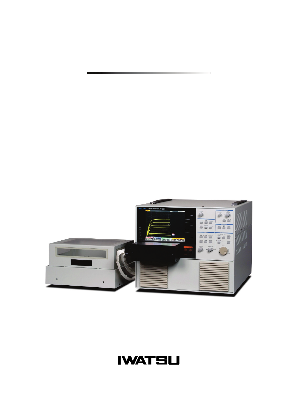
Iwatsu CS-3000 Series User manual

Instruction Manual
Curve Tracer
CS-3000 series
CS-3100
CS-3200
CS-3300

Ⓒ2010 IWATSU ELECTRIC CO., LTD. All rights reserved.

i
Preface
Thank you for purchasing the Curve Tracer CS-3000 Series. Please use IWATSU instruments
regularly for a long time in future.
Please read this manual carefully and understand its contents before using this instrument, and
then keep this manual handy for future reference.
This instruction manual describes the precaution, installation and operation of the following
Curve tracer CS-3000 series: CS-3100/CS-3200/CS-3300.
The following manual, including this one, is provided as manual for the Curve Tracer 3000
Series.
The CS-3000_5000 Series Remote Control Manual explains the remote control for the Curve
Tracer used the usual LAN interface through 10Base-T/100Base-TX and adopts VXI-11 as the
communication protocol. Please read the manual, too.
Notices
This manual describes the Curve Tracer CS-3000 Series of software version 1.38.
Parts of the contents of this manual may be modified without notice for improvements in
performance and functions.
Reproduction or reprinting of the contents of this manual without prior permission from Iwatsu
is prohibited.
For questions about this instrument, contact IWATSU ELECTRIC CO., LTD. listed at the end of
this manual or our sales distributors.
Manual Part Number KML105061
Revision history
February 2010: 1st edition
September 2016: 11th edition
May 2017: 12th edition
October 2017: 13th edition
July 2018: 14th edition
July 2020: 15th edition
Important Safety Precautions
To ensure safe operation of this instrument and to prevent injury to the user or damage to property,
items to be observed are written in the WARNING and CAUTION in this manual. Be sure
to read them for safe operation. In addition, marks indicating attention are attached on the panel.
Definitions of WARNING and CAUTION used in this manual
WARNING Incorrect operation or failure to observe the warning may
result in death or
serious injury.
CAUTION Incorrect operation or failure to observe the caution may result in injury or
damage to the instrument.
Explanation of symbols on panel
ELECTRIC SHOCK
Incorrect operation may cause electric shock. This symbol calls attention. To
protect the user, read items in this manual before using this instrument.
WARNING
To prevent injury to the user or damage to this instrument, read items in this
manual before using this instrument.

ii
Read this page to ensure proper safety. (Also read the following pages.)
WARNING
●In measurement with this instrument, high voltage may be
applied and high current may be supplied. Always close the
cover before measurement after setting the DUT (Device
Under Test) on the test fixture.
High voltage (max. 3kV) may be applied and high current (max. 1000A) may be supplied to the
terminal to which the DUT is mounted. To prevent danger, if the cover of the test fixture is not closed,
no voltage and current can be supplied to the terminal and no power can be applied to the DUT. And,
do not remodel the switch for power supply shutoff or do not open the cover during measurement. If
not, electric shock may be caused.
●Do
not open the cover of the test fixture during
measurement.
High voltage (max. 3kV) and high current (max. 1000A) may be applied to the terminal to which the
DUT is mounted. To prevent danger or to protect the DUT, when detecting that the cover of the test
fixture opens, the instrument immediately shuts off the voltage and current applied to the terminal and
stops the power supply to the DUT. And for safety, do not open the cover of the test fixture during
measurement.
●After measurement, the DUT may be charged. Do not touch
the DUT until discharging it through the grounding rod and
confirming the safety.
Touching the charged DUT may cause electric shock.
●Do not use other than attached Test Lead sets
(alligator-banana clip)
(Only for CS-3200/CS-3300)
If measurement is done without considering measurement electric potential and usage rating of the cable
outer cover and GND cable outer cover, fire or failures may be caused. Use the specified cables
attached depending on measurement types.

iii
Read this page to ensure proper safety. (Also read the following pages.)
WARNING (Continued)
●If you notice smoke, abnormal smell or abnormal sound,
immediately take measures below and remove the power
plug from the receptacle.
(1) Make the power switch a standby.
(2) Remove the power plug from the receptacle.
Continued use under these circumstances may result in electric shock or fire. After taking measures
above, contact Iwatsu office or our sales distributors for repair. Repairing the instrument yourself is
very dangerous. Do not attempt to repair the instrument under any circumstances.
●Do not use in an environment with explosive gases.
This may result in explosion.
●Make sure no water gets on or inside the instrument.
Failure to observe this precaution may result in electric shock or fire. If water gets on or inside the
unit, after making the power switch a standby, and pulling out the power plug from the power
receptacle,contact Iwatsu office or our sales distributors for repair.
●Do not touch the plug of the power cord if your hands are
wet.
This may result in electric shock.
●Do not place this instrument on an unstable place such as
a shaky stand or inclined place.
Letting this instrument fall or topple down may result in electric shock, fire or injury. If this instrument
falls or its cover is damaged, after making the power switch a standby, and pulling out the power plug
from the power receptacle, contact Iwatsu office or our sales distributors for repair.
●Surely insert the power plug into the power receptacle
after checking that any dust is not sticking to the power
plug. Additionally, disconnect the power plug or power
adaptor from the power receptacle
once every six
months to one year, and inspect and/or clean the power
plug.
If the power plug is contaminated, this may cause an electric shock, a fire, or a malfunction.

iv
Read this page to ensure proper safety. (Also read the following pages.)
WARNING (Continued)
●Do not put any foreign objects, such as metallic or
flammable objects through the ventilation port.
If any foreign object of metal and the combustible one, etc. is put through the ventilation port, this
may result in electric shock, fire, and/or malfunction.
If any foreign object enters this instrument, after making the power switch a standby, and pulling out
the power plug from the power receptacle, contact Iwatsu office or our sales distributors for repair.
●Always use a 3-prong power cord that suits power supply
voltage for this instrument.
Using a power cord that is incompatible with the power voltage may result in electric shock, fire and/or
malfunction. Additionally, using a 2-prong power cord may result in electric shock.
Unless otherwise specified at purchase, a 100V (90 V to 132 V) power cord is supplied with the
instrument. If operating the instrument at 200V (180 V to 250 V), always use the 3-prong power cord
(optional) for 200V systems (rating: 250V) specified by Iwatsu.
- If the power is supplied from the 2-wire receptacle using the 3-prong/2-prong conversion adapter,
ground the GND terminal of the adapter.
- When using the attached 3-prong power cord to supply the power from the 3-wire receptacle,
grounding is made through the GND line of the power cord.
●Use this instrument at a specified supply voltage.
Using this instrument at a voltage other than specified may result in electric shock, fire or
malfunction. Usable power supply voltage range is written on the rear panel.
●Do not remove the case, cover and panel.
Since there are parts with a high voltage in this instrument, touching the part may cause electric
shock. When performing inspection, calibration, or repair, contact Iwatsu office or our sales
distributors.
●When handling power cord, observe items below:
If not, fire or electric shock may occur. If the power cord is damaged, contact Iwatsu office or our
sales distributors for repair.
- Do not attempt to fabricate the power cord.
- Do not pull the power cord.
- Do not forcibly bend the power cord.
- Do not heat the power cord.
- Do not twist the power cord.
- Avoid getting the power cord wet.
- Do not bind the power cord together.
- Do not place heavy objects on the top of the power cord.
●Do not modify or repair this instrument.
Modifications or repairs made by users may result in an electric shock, a fire, or a malfunction. This
instrument cannot be repaired by users. Do not open it to attempt repairs. For repairs, contact Iwatsu
office or our sales distributors. Note that modified products will not be accepted for repairs.

v
Read this page to ensure proper safety. (Also read the following pages.)
WARNING (Continued)
●If a lightning occurs near the instrument operation place, immediately make the
power switch a standby and
disconnect the power plug from the power
receptacle.
A lightning may cause an electric shock, a fire, or a malfunction.
●Do not allow metal objects, etc., to touch the metal blades of the power plug.
Contact with a metal object, etc., may cause a fire or electric shock.
●Do not use multiple-connection receptacles.
Power strips and other multiple-connection receptacles may cause a fire or overheating.
●Do not place containers of water or chemicals, small metal objects, etc. near this
instrument.
If the contents are spilled and enter the instrument, it may cause a fire or an electric shock. If water,
chemicals, or metal objects enter the instrument, set the power switch to standby, remove the plug
from the receptacle, and then contact Iwatsu office or our sales distributors for repair.
●Do not use this instrument if it is not functioning correctly.
Using a malfunctioning instrument (due to dropping, etc.) may cause an electric shock or a fire.
If the instrument is not functioning correctly, set the power switch to standby, remove the plug from
the receptacle, and then contact Iwatsu office or our sales distributors for repair.
●Do not place this instrument in an area where frequent vibrations or impacts
occur.
If this instrument is dropped or overturned, it may cause a physical injury.
●If this instrument is dropped, it may result in a physical injury or property
damage.
Before transporting this instrument, remove all devices under testing, probes, and cables,
and then carry it carefully by two people or more to avoid dropping.
●Always use a 3-prong power cord applicable to the power voltage.
When using a power cord not applicable to the power voltage, fire may occur.
In addition, use of 2-prong power cord may cause electric shock.
Unless specified when purchasing the instrument, the power cord for the 100V system (90V
to 132V) is supplied with this instrument. If this instrument is operated with the power voltage
changed to the 200V system (180 to 250V), always use the 3-prong power cord for the 200V
system (rating: 250V) specified by our company (option).
●When disconnecting the power cord from the receptacle, hold the plug to pull it out
Pulling the power cord may damage it, resulting in electric shock or fire.

vi
Read this page to ensure proper safety. (Also read the following pages.)
CAUTION
●Set the power supply cord up in the place where it is pulled out easily.
When this instrument is a dicey situation, it is necessary to cut power off promptly. Do not
attempt to place this instrument in the location where difficult to remove the power
supply cord from the receptacle.
●Do not use the power cord attached to this instrument for other electric apparatuses.
The power cord attached to this instrument cannot be used for other electric apparatuses in
accordance with the electric apparatus safety laws.
●Connect or disconnect the power cord after the POWER switch has been made a
standby.
If not, fire or overheating may be caused.
●Do not short-circuit the blade of the power cord plug with metal and others.
If touched with metal, fire or electric shock may be caused.
●Do not use any damaged power cord, cable or adaptor.
If any damaged power cord, cable or adaptor is used, this may result in electric shock and/or
fire.
●Do not place an object on this instrument.
The cover comes in contact with an internal circuit when the objedt is put on this instrument,
and then electric shock, fire, or failures may be caused.
●Do not place an object near the ventilation port and fan of this instrument.
This may cause the inside to be filled with heat, resulting in fire or failures.
●Ensure the spaces at the both sides and rear side of this instrument.
Otherwise, this may cause operation or performance to be failed. Open the space of about
100mm to the left side, the right side, and the back of this instrument. When mounting it on
the other instrument, attenstion should be directed to temperature increase.
●When connecting wire to DUT(device under test), check indications of each terminal
and carefully avoid incorrect wiring.
Incorrect wiring may conduct wrong measurement. Also mis-connection may cause of
damage on DUT and/or malfunction of the unit.
・When wrongly connecting Collector terminal and Base terminal;
DUT may be damaged while extra high voltage can be supplied on Base terminal.
・When NOT connecting Collector output terminal, Base output terminal and Emitter
terminal and connecting Collector sense terminal, Base sense terminal and/or Emitter
sense terminal respectively;
It may cause for burn of SENSE RESISTERs inside of the unit since the sense resisters
connected to outputs respectively for Kelvin sensing and may be supplied current
exceeding each specification.
・When connecting HIGH VOLTAGE terminal and HIGH CURRENT terminal of collector
output at the same time on DUT;
It may be cause for fire and/or malfunction due to high voltage applied to HIGH
CURRENT terminal. When changing test conditions, change wiring properly and
accordingly. Avoid to connect multiple outputs on the same terminal. This unit has 5(five)
kinds of outputs as HIGH VOLTAGE output of Collector, HIGH CURRENT output of
Collector, Base output, Emitter output and AUX output.

vii
Read this page to ensure proper safety. (Also read the following pages.)
CAUTION (Continued)
●Do not place this instrument in the location with much moisture (bathroom, etc.) or
dirt.
If not, electric shock or fire may be caused.
●Do not expose this instrument to the direct sunlight or with much moisture.
Direct sunlight may the inner temperature to increase, resulting in fire.
●Do not place this instrument in a location next to a worktable or humidifier, where it
may be exposed to oily smoke or steam.
Doing so may cause an electric shock or fire.
●Before moving this instrument, remove the power cord and external connection
cables from this instrument.
If not, the cord or the cable may be damaged, resulting in fire or electric shock.
●When connecting the power cord or measurement cable, care should be taken so that
you do not pull such cable. If such cable is pulled, this may cause the instrument to be
laid down.
If this instrument is laid down, this may cause an electric shock, a personal injury, a fire, or a
malfunction.
●Use this instrument within the specified operation and storage range.
Using outside a regulated system requirements or keeping it outside a regulated
environmentmay cause malfunction.
If not, an failure may be caused. Usable temperature range is as follows:
- Only indoor use
Operation temperature : 0 °C to +40 °C
Operation humidity :5 % to 80 %RH (at 30 °C or less) and no dew condensation allowed
Upper bound value : 55 %RH (at 40 °C) and no dew condensation
allowed
Storage temperature : -20 ℃~+60 ℃
Storage humidity : 5 %~80 %RH (no dew condensation allowed )
●When transporting this instrument, detach the power cord, the cable, and the adaptor,
etc. and use the packing material provided at the time of purchase or packing material
equivalent at least.
Excessive vibration or shock applied to this instrument during transportation may cause it to
malfunction, resulting in fire. If you do not have the proper packing material or shock
absorbing material, contact Iwatsu office or our sales distributors. When having the intrument
transported by a shipping company, write "Precision Instrument - Handle With Care" on each
side of the packing box.
●Prior to maintenance, remove the power plug from the receptacle for safety. Use a
cloth to wipe away any moisture.
Cleaning this instrument while the power plug is connected to the receptacle
or while the
instrument is wet may cause an electric shock or a malfunction.

viii
Read this page to ensure proper safety. (Also read the following pages.)
CAUTION (Continued)
●If not used for a long time, remove the power cord plug of this instrument from the
receptacle for safety.
●Do not use the instrument without cleaning internal for a long term.
Long-term use of an instrument having a dirty or dusty interior may cause a fire or
malfunction. It is recommended that you contact Iwatsu office or sales distributors to check
and clean the interior, calibrate, etc., about once per year.
●The weight of this instrument is about 43 kg for CS-3200/CS-3300 and about 28 kg for
CS-3100. When moving or transporting it, two persons or more should carry it.
If not, injury may be caused.
●When "OVERHEAT ALERT!!!" or "Overheat alert was detected." is displayed, the inner
temperature is high: i.e., overheating state. When the overheating is displayed, stand
by for five minutes or more (the time that an in-flight temperature falls enough) after
the breaker of "COLLECTOR SUPPLY" is switched to "Disable", and return to
"Enable", and restart the measurement. After that, output of current and voltage is
automatically set to 0. Wait un54he indication disappears while keeping the power on
state (fan moving).
Since the fan moves when the power switch is on, the inner temperature is easy to decrease.
If the power switch is turned off, it takes much time to decrease the temperature.
●Please work carefully so that neither the hand nor the finger, etc. are placed when you
handle the lid of the test fixture on.
It might cause the injuries such as hands and fingers when placed.
●Please use special red Test Leads in the connection of the collector terminal when
you measure high voltage (HIGH VOLTAGE).
When the Test Leads other than red are used, the resisting voltage might damage the
measurement sample and this instrument due to the insufficiency.
●Do not apply a voltage exceeding 1 kV (500 V for CS-510) or a current exceeding 1A on
each terminals of the test adapters (TO type adapter option) CS-501A , CS-502 (AXIAL
type adapter option) and CS-503/CS-504/CS-505/CS-506/CS-510 (SURFACE MOUNT
type adapter options). And, do not apply a voltage exceeding 100 V or exceeding 0.5 A
on each terminal of the test adapter (SURFACE MOUNT type adapter option)
CS-507/CS-509. Moreover, do not apply a voltage exceeding 3 kV or exceeding 40 A on
each terminal of the test adapter (SMD CHIP type adapter option) CS-508.
If the above-mentioned voltage values and current values are exceeded, test adapter
intrument or a device to be measured might be damaged.
●Avoid the measurements of parts other than the semiconductor device because the
measurements might cause the breakdown of this instrument and the damage of the
measurement device. Moreover, when you measure the semiconductor device that has
not been described to this manual, contact Iwatsu office or our sales distributors.
●Do not use this instrument by method of no regulations with this instruction manual.
If not, protection means does not function.

ix
Items
When receiving this instrument, please verify items in the package.
♦Main body of curve tracer .........................................................................: 1
Test fixture
- CS-302 (for CS-3200/ for CS-3300).........................................................: 1 set
- CS-301 (for CS-3100)..............................................................................: 1 set
* Either depending on CS-3300/CS-3200 or CS-3100
<Accessories>
- Test adapter CS-500 (Blank adapter) .........................: 1 set
- Test Lead set CS-005 (only for CS-3200/CS-3300) .................................: 1 set (7 wires)
For collector (voltage and SENSE, red) ...............................................: 2
For base (voltage and SENSE, black)..................................................: 2
For emitter (voltage and SENSE, green)..............................................: 2
For AUX (yellow)..................................................................................: 1
- Power cord (3-prong)...............................................................................: 1
- Cord strap................................................................................................: 1
- Instruction manual (this document) ..........................................................: 1
- Instruction manual and Remote control manual (as PDF files in CD).......: 1
The following options are delivered when the purchase is specified.
♦Option
- Semiconductor parameter search option CS-800 ....................................: 1 set
- DOUBLE SWEEP option CS-801 ............................................................: 1 set
* It is delivered simultaneously that two above-mentioned kinds of are optional with the main
unit when bought while installed in the main unit. (The USB memory is appended. )
Install, and use the data collected to an attached USB memory when the option is bought after
main unit is bought.
- Test adapter CS-501A (TO type adapter) ................................: as requested
Insulation tab ........................................................................: 1 piece (with CS-501A)
Short-circuit terminal...............................................................: 1 piece (with CS-501A)
- Test adapter CS-502 (AXIALTO type adapter).........................: as requested
- Test adapter CS-503 (SURFACE MOUNT type adapter).........: as requested
- Test adapter CS-504 (SURFACE MOUNT type adapter).........: as requested
- Test adapter CS-505 (SURFACE MOUNT type adapter).........: as requested
- Test adapter CS-506 (SURFACE MOUNT type adapter).........: as requested
- Test adapter CS-507 (SURFACE MOUNT type adapter).........: as requested
- Test adapter CS-508 (SMD CHIP type adapter) ......................: as requested
- Test adapter CS-509 (SURFACE MOUNT type adapter).........: as requested
- Test adapter CS-510 (SURFACE MOUNT type adapter).........: as requested
- Alligator clip for curve tracer CS-001 (red) ...............................: as requested (1 set: 10 clips)
- Alligator clip for curve tracer CS-002 (black)............................: as requested (1 set: 10 clips)
- Test Lead set for high voltage CS-003 (red) ............................: as requested (1 set: 5 wires)
- Test Lead set CS-004 (black) ..................................................: as requested (1 set: 5 wires)

x
How to use this document; Notation
It is recommended that the biginner of this instrument should use the instrument after reading this
instrumecion manual carefully.
♦Explanation of each section
Sections which mainly explain the function, operation, and specification consist of:
Outline (only for Chapter 4)
Inside of the frame describes the purpose, application, and main point (important items in bold
and large characters)
Operation procedure
Step-by-step procedure is shown.
Examples of setting and measurement
It includes the operation method, explanation diagram, and detailed explanation.
Warning caution, memo
WARNING and CAUTION for electric shock, fire, and damage to this instrument are written at
the begining of this manual.
Explanation of each section includes CAUTION and memo (knowhow and details).
♦Usage example of caution and memo
Caution
Memo
Updating version of software
Since each software program has suitability to a machine, contact Iwatsu office or our sales
distributors for software version update or visit on our Web site (URL : http://www.iti.iwatsu.co.jp).
For the procedure of the version updating software in the main unit, refer to the section 3.11.1.6
Updating software in the instrument.
Caution !
When transferring to an environment with different temperature and humidity, sudden temperature
change may cause dew condensation. In such a case, this instrument should be inured to the
ambient temperature before using it; ambient temperature gradually changes.
Memo
Kelvin Sense
Since voltage drop caused by the contact resistance of a contact is not included in measurement,
high accuracy measurement can be attained.

0-1
Contents
Capter 1 Overview ............................................................................................................................. 1-1
1.1 Features......................................................................................................................................... 1-1
Capter 2 Name and Function of Each Part (Outline)...................................................................... 2-1
2.1 Name and outline of each part on front panel ............................................................................... 2-1
2.1.1 Function keys and FUNCTION knob..................................................................................... 2-2
2.1.2 STEP GENERATOR ............................................................................................................. 2-3
2.1.3 COLLECTOR SUPPLY ......................................................................................................... 2-4
2.1.4 MEASUREMENT .................................................................................................................. 2-6
2.1.5 DISPLAY ............................................................................................................................... 2-7
2.1.6 SYSTEM................................................................................................................................ 2-8
2.2 Name and function of each part on rear panel .............................................................................. 2-9
2.3 Test fixture CS-302...................................................................................................................... 2-10
2.4 Test adapter CS-500 (Blank adapter) ......................................................................................... 2-12
2.5 Test fixture CS-301...................................................................................................................... 2-13
2.6 Test adapter CS-501A (TO type adapter, option) ....................................................................... 2-15
2.7 Test adapter CS-502 (Axial type adapter, option) ....................................................................... 2-17
2.8 Test adapter CS-503/CS-504/CS-505 (Surface mount type adapter, option) .......................... 2-19
2.9 Test adapter CS-506 (Surface mount type adapter, option) ....................................................... 2-21
2.10 Test adapter CS-507/CS-509 (Surface mount type adapter, option)........................................ 2-23
2.11 Test adapter CS-508 (SMD CHIP type adapter, option) ........................................................... 2-25
2.12 Test adapter CS-510 (Surface mount type adapter, option) ..................................................... 2-27
Capter 3 Function Setting and Basic Operation............................................................................. 3-1
3.1 Measurement operation flow ......................................................................................................... 3-2
3.2 Setting up this instrument.............................................................................................................. 3-3
3.3 Preparation before measurement.................................................................................................. 3-4
3.3.1 Connecting the power cord ................................................................................................... 3-4
3.3.2 Connecting the test fixture with the main body ..................................................................... 3-5
3.3.3 Connecting the patch panel (only for CS-302) ...................................................................... 3-7
3.3.4 Connecting the measured device with the test adapter CS-500........................................... 3-9
3.3.5 Connecting the measured device with the test adapter CS-501A (Option) ........................ 3-10
3.3.6 Connecting the measured device with the test adapter CS-502 (Option)........................... 3-11
3.3.7 Connecting the measured device with the test adapter CS-503/CS-504/CS-505/CS-506
(Option) ........................................................................................................................... 3-12
3.3.8 Connecting the measured device with the test adapter CS-507/CS-509 (Option) ............. 3-14
3.3.9 Connecting the measured device with the test adapter CS-508 (Option)........................... 3-15
3.3.10 Connecting the measured device with the test adapter CS-510 (Option)......................... 3-16

0-2
3.4 Screen structure .......................................................................................................................... 3-17
3.5 Setting with function keys and knobs .......................................................................................... 3-19
3.6 Setting step generator ................................................................................................................. 3-20
3.6.1 Setting STEP knob .............................................................................................................. 3-21
3.6.2 Setting STEP 1/10 key ........................................................................................................ 3-22
3.6.3 Setting OFFSET knob ......................................................................................................... 3-23
3.6.4 Setting MENU key ............................................................................................................... 3-24
3.7 Setting collector supply................................................................................................................ 3-27
3.7.1 VARIABLE knob .................................................................................................................. 3-29
3.7.2 MODE/POLARITY keys....................................................................................................... 3-30
3.7.3 POWER−WATT key ............................................................................................................ 3-32
3.7.4 VOLTS key .......................................................................................................................... 3-33
3.7.5 ACQUIRE key...................................................................................................................... 3-34
3.7.6 LOOPING COMPENSATION key ....................................................................................... 3-37
3.8 Setting measurement .................................................................................................................. 3-38
3.8.1 REPEAT .............................................................................................................................. 3-38
3.8.2 SINGLE ............................................................................................................................... 3-38
3.8.3 SWEEP................................................................................................................................ 3-38
3.9 Setting with HORIZONTAL knob/ VERTICAL knob .................................................................... 3-40
3.9.1 HORIZONTAL knob............................................................................................................. 3-42
3.9.2 VERTICAL knob .................................................................................................................. 3-44
3.10 Setting DISPLAY part menus .................................................................................................... 3-46
3.10.1 MENU key ......................................................................................................................... 3-47
3.10.2 INVERT key....................................................................................................................... 3-48
3.10.3 VIEW/PULSE key .............................................................................................................. 3-49
3.10.4 CURSOR key .................................................................................................................... 3-53
3.10.5 ZOOM key ......................................................................................................................... 3-58
3.10.6 POSITION key................................................................................................................... 3-59
3.11 Setting SYSTEM part menus..................................................................................................... 3-61
3.11.1 UTILITY key....................................................................................................................... 3-62
3.11.2 COPY key.......................................................................................................................... 3-84
3.11.3 SAVE/RECALL key ........................................................................................................... 3-85
3.11.4 Setting of SAVE/RECALL/DELETE (saving/recalling/deleting data) ................................ 3-92
3.11.5 CONFIGURATION key.................................................................................................... 3-100
3.11.6 AUX key........................................................................................................................... 3-104
3.11.7 APPLICATION key (option)............................................................................................. 3-105
3.11.8 Default settings................................................................................................................ 3-119
Capter 4 Characteristics Measurement ........................................................................................... 4-1
4.1 Quick start guide............................................................................................................................ 4-2

0-3
4.1.1 Diode measurement .............................................................................................................. 4-2
4.1.2 Transistor measurement ..................................................................................................... 4-10
4.1.3 Measurement....................................................................................................................... 4-23
4.2 Characteristics measurement...................................................................................................... 4-34
4.2.1 IGBT characteristics measurement..................................................................................... 4-34
Capter 5 Daily Maintenance and Calibration .................................................................................. 5-1
5.1 Daily maintenance ......................................................................................................................... 5-1
5.2 Calibration...................................................................................................................................... 5-3
5.3 Repair and sending of repaired instrument ................................................................................... 5-3
5.4 Storage and transportation ............................................................................................................ 5-3
Capter 6 Specifications..................................................................................................................... 6-1
6.1 Instrument specifications ............................................................................................................... 6-1
6.2 Compliance standards................................................................................................................... 6-5
6.3 Outside view .................................................................................................................................. 6-6
6.3.1 Main unit CS-3100................................................................................................................. 6-6
6.3.2 Main unit CS-3200/CS-3300 ................................................................................................. 6-6
6.3.3 Test fixture CS-302 ............................................................................................................... 6-7
6.3.4 Test adapter CS-500 (Blank adapter) ................................................................................... 6-8
6.3.5 Test fixture CS-301 ............................................................................................................... 6-9
6.3.6 Test adapter CS-501A (TO type adapter, option) ............................................................... 6-10
6.3.7 Test adapter CS-502 (Axial type adapter, option)............................................................... 6-11
6.3.8 Test adapter CS-503 (Surface Mount type adapter, option) ............................................... 6-12
6.3.9 Test adapter CS-504 (Surface Mount type adapter, option) ............................................... 6-13
6.3.10 Test adapter CS-505 (Surface Mount type adapter, option) ............................................. 6-14
6.3.11 Test adapter CS-506 (Surface Mount type adapter, option) ............................................. 6-15
6.3.12 Test adapter CS-507 (Surface Mount type adapter, option) ............................................. 6-16
6.3.13 Test adapter CS-508 (SMD CHIP type adapter, option)................................................... 6-17
6.3.14 Test adapter CS-509 (Surface Mount type adapter, option) ............................................. 6-18
6.3.15 Test adapter CS-510 (Surface Mount type adapter, option) ............................................. 6-19


Capter 1 Overview
Curve Tracer CS-3000 Series Instruction Manual 1-1
Capter 1 Overview
Development of semiconductor technologies is remarkable and diverse; in particular, components
including power devices such as inverters are expanding and progress in the technology for them is
striking in such facilities as heavy electrical equipment (electric power), home electric products, air
conditioning, and traffic. In power electronics technologies, existing pursuit of high efficient use of
power is changing to pursuit of reduced energy density (compacting) or ECO gentle to the
environments. Part development for ECO products is progressing rapidly in transportation industries
such as electric train, automobile industries, and power device manufacturers.
Inverter technologies used in various electronic components such as the air conditioner, refrigerator,
elevator, electric train, hybrid car, solar power generation, and wind power generation are essential
for saving energy. Importance of evaluating power semiconductor devices is increasing to improve
the efficiency in use of energy.
The curve tracer CS-3000 series have been developed to evaluate power semiconductor devices in
such a power electronics market. Section 1.1 below shows features of CS-3000.
1.1 Features
CS-3000 is the newest instrument which can support up to the maximum peak voltage of 3000V
and the maximum peak current of 1000A. It can be used not only for characteristics measurement
of high-voltage or high-current power devices such as the latest IGBT and power MOSFET but also
for characteristics measurement of various semiconductor devices such as transistors, diode, and
LEDs. The measurement results can be saved in the memory or sent to the PC through the USB
port and LAN interface which are attached as standard. Main features are as follows:
∗CS-3000 series include 3 models: CS-3100, CS-3200, and CS-3300.
■Peak voltage
All models of CS-3000 series have the maximum peak voltage of 3000 V for collector supply.
■High current mode installed
Models of CS-3200/CS-3300 install the high current mode (HC mode)
- CS-3200: Up to maximum collector current of 400 A
- CS-3300: Up to maximum collector current of 1000 A
■All models have 4 collector supply modes.
They have 4 collector supply modes: AC, full-wave rectified, DC, and leakage current as
standard.
Both CS-3200 and CS-3300 can supply the maximum of 40 V pulse in the high current mode
(HC mode).
■Handling a measured device
A measured device is set in either of two methods below:
- Connect the terminals of a measured device to the specified terminals in the test adapter, and
set the test adapter in the test fixture. There are CS-500 of standard equipment and CS-501A
to CS-510 options in test adaptors. Refer to Section 2.3 to Section 2.12 for details.
- Connect the terminals of a measured device directly to the specified terminals of the test
fixture through the dedicated wires (Refer to Section 2.3 section for details only when you use
test fixture CS-302.
The test fixture with the measured device mounted is connected to the main unit through the
cable and the connector box. (For details, see Section 3.3.)

Capter 1 Overview
1-2 Curve Tracer CS-3000 Series Instruction Manual
■Remote control function
CS-3000 supports LAN interface (10 Base-T/100 Base-TX Ethernet). External connection uses
LAN terminal on the rear panel. For details; e.g., usage and commands, see Remote Control
Manual recorded in the attached CD.

Capter 2 Name and Function of Each Part (Outline)
Curve Tracer CS-3000 Series Instruction Manual 2-1
Capter 2 Name and Function of Each Part (Outline)
This section outlines the name and the function of each part in this instrument.
Section 2.1 and Section 2.2 briefly explain names and functions of keys and connections on the front
and rear panels.
Section 2.3 to Section 2.10 briefly explain names and functions of parts on the test fixture and the
test adapter.
2.1 Name and outline of each part on front panel
Figure 2.1 shows the front panel of CS-3200/3300 (This instrument does not have HIGH CURRENT
part
⑧
) and Table 2.1 lists name and function of each part.
Figure 2.1 Front panel
Table 2.1 Name and function of each part on front panel
№
Name
Description
①
LCD screen
8.4-inch color LCD. It displays various setting screens and menus.
②
Power supply switch
It switches On/Standby.
③
USB terminal
Terminal to input/output data from/to USB memory.
It can be used for saving/recalling setup data (setting conditions) and
waveform data (TRACE/REF), and screen hard copy. (For handling USB
memory, see Section 3.11.)
④
Input/output terminals
They are connected with the test fixture through the connector box.
⑤
Function keys
CLEAR key
On the right side of LCD, keys below are arranged in sequence from the
top.
•Function keys: F1 to F6 from the top
•CLEAR key
It is used to eliminate the function menu. However, if the submenu
appears, it allows the submenu to return to the previous menu.
⑥
Various menu keys
Various menu keys are arranged. For these keys, see Section 2.1.1 to
Section 2.1.6.
⑦
Breaker for
COLLECTOR
SUPPLY
It switches ENABLED/ DISABLED for the collector supply output with the
breaker switch (upper diagram) for protection of a measured device from
overcurrent/overvoltage. When DISABLED, the menu can be set but
nothing is generated and measured. If ENABLED, measurement can
be made.
CS-3100: only HIGH VOLTAGE
CS-3200/3300: both HIGH VOLTAGE & HIGH CURRENT
⑧
HIGH CURRENT
Included in CS-3200/3300
⑦
Breaker for COLLECTOR SUPPLY

Capter 2 Name and Function of Each Part (Outline)
2-2 Curve Tracer CS-3000 Series Instruction Manual
2.1.1 Function keys and FUNCTION knob
Figure 2.2 shows function keys and FUNCTION knob on the front panel and Table 2.2 lists name
and function of each part.
Figure 2.2 Front panel (function keys, FUNCTION knob)
Table 2.2 Front panel (function keys, FUNCTION knob)
№
Name
Description
Ref.
①
Function keys Keys to select submenus displayed on the right side on the LCD. The
surface of these keys on the panel shows no character but they are
called "Function keys" in this manual (F1 to F6 from the top).
Pressing one of them allows the corresponding submenu to open
and the corresponding function to be carried out.
Section
3.5
②
FUNCTION knob FUNCTION knob is used to select submenus on the right side on the
LCD when the function menu is selected. It is available only when
icon appears on the submenu.
Pushing FUNCTION knob allows transfer among base steps and
switchover of a side to be moved during cursor measurement.
Section
3.5
Function keys
FUNCTION knob
This manual suits for next models
3
Table of contents
Other Iwatsu Laboratory Equipment manuals
Popular Laboratory Equipment manuals by other brands

Medivators
Medivators ADVANTAGE 78400-117 Maintenance instructions

Gilson
Gilson Pipetman M quick start guide

Brightwell
Brightwell Brightlogic 2 Full Installation Guide

Endress+Hauser
Endress+Hauser Liquistation CSF33 operating instructions

Thermo Scientific
Thermo Scientific Cryofuge 16 instruction manual

BioLAB
BioLAB BCLT-201 Operation manual