Iwatsu SS-530 User manual

Instruction Manual
Current Probe
SS-530 / SS-531

Ⓒ2021 IWATSU ELECTRIC CO., LTD. All rights reserved.

Measurement Procedure
Be sure to familiarize yourself with the “Usage Notes”
section (p. 8), each instruction of use, and safety notes
presented at the beginning of each instruction of use.
Inspecting the Device Before Use (p. 26)
Preparing for Measurement (p. 28)
•Provide power to the device.
•Connect the termination unit to your waveform
measuring instrument.
•Execute demagnetization and automaticzero-
adjustment.
Measuring Currents (p. 41)
•Clamp the sensor around a conductor tobe
measured.
•Measure a current.
Finishing Measurement (p. 65)

Waveform measuringinstrument
H
L
Power source
Load
Model PS-54 Power
Supply
Connection Example
See “Example of connection to the circuit to be measured”
(p. 49).

CONTENTS
Introduction................................................................................1
Notations ....................................................................................2
Checking Package Contents.....................................................5
Safety Notes ...............................................................................7
Usage Notes ...............................................................................8
1 Overview.............................................................................13
1.1 Product Overview ...................................................................... 13
1.2 Product Features ....................................................................... 14
1.3 Name and Function of Each Part ............................................. 16
Termination unit ........................................................................ 16
Junction box (keys, LEDs) ....................................................... 18
Sensor ........................................................................................ 20
1.4 Specifications of Lighting Up / Blinking LEDs........................ 22
2 Current Measurement.........................................................25
2.1 Inspecting the Device Before Use............................................ 26
2.2 Preparing for Measurement...................................................... 28
Providing power to the SS-530/SS-531 ................................... 29
Executing demagnetization and
automatic zero- adjustment...................................................... 33
2.3 Measuring Currents................................................................... 41
How to measure a current ........................................................ 50
To measure a low current......................................................... 58
To measure a current accurately............................................. 60
When the device has entered protection mode...................... 62
2.4 Finishing Measurement............................................................. 65

3 Specifications.....................................................................69
3.1 General Specifications.............................................................. 69
3.2 Specifications of Input, Output and Mesurement................... 71
Basic specifications.................................................................. 71
Specifications of accuracy....................................................... 73
3.3 Specifications of Functionality................................................. 75
3.4 Typical Characteristics ............................................................. 77
Frequency characteristics........................................................ 77
Frequency derating curve ........................................................ 78
Input impedance........................................................................ 80
Consumption current................................................................ 81
Influence of common-mode voltage........................................ 82
4 Maintenance andService ...................................................83
4.1 Troubleshooting ........................................................................ 84
Before sending back your device for repair ........................... 85
4.2 Errors.......................................................................................... 88
Types of errors .......................................................................... 89
4.3 Cleaning...................................................................................... 96
4.4 Disposal...................................................................................... 97

1
Introduction
Introduction
Thank you for choosing the IWATSU SS-530, SS-530
Current Probe. To ensure your ability to get the most out of
this device over the long term, please read this manual
carefully and keep it available for future reference.
Each model offers a different frequency band listed below:
Model SS-530: DC to 50 MHz
Model SS-531: DC to 120 MHz
To obtain maximum performance from the device, please
read this manual first, and keep it handy for future reference.
Target audience
This manual has been written for use by individuals who use
the product in question or who teach others to do so.
It is assumed that the reader possesses basic electrical
knowledge (equivalent to that of someone who graduated
from the electrical program at a technical high school).
2
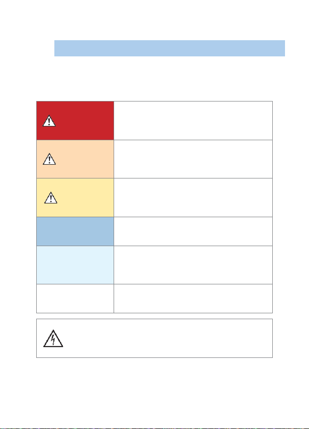
Indicates a high-voltage hazard.
Failure to verify safety or improper handling of the device
could lead to electric shock, burn injury, or death.
Notations
Notations
Safety notations
This manual classifies seriousness of risks and hazard
levels as described below.
DANGER
Indicates an imminently hazardous situation
that, if not avoided, will result in death or
serious injury.
WARNING
Indicates a potentially hazardous situation
that, if not avoided, could result in death or
serious injury.
CAUTION
Indicates a potentially hazardous situation
that, if not avoided, could result in minor or
moderate injury.
NOTICE
Indicates potential risks of damage to the
supported product (or to other property).
IMPORTANT
Indicates information or content that is
particularly important from the standpoint of
operating or maintaining the device.
NOTE
Indicates useful advice concerning device
performance and operation.

3
Indicates an action that must be performed.
Indicates that the device can only be used at a location
on an insulated wire with sufficient insulation for the
circuit voltage.
Indicates the presence of a potential hazard. For more
information about locations where this symbol appears
on device components, see the “Usage Notes” section
(p. 8), warning messages listed at the beginning of
operating instructions.
Notations
Symbols shown on the device
Symbols for various standards
Indicates an action that must not be performed.
Indicates that the product complies with standards
imposed by EU directives.
Indicates the Waste Electrical and Electronic Equipment
Directive (WEEE Directive) in EU member states.

4
Bold
Indicates the names of the control keys.
*
Indicates additional information is described below.
rdg.
Reading (Displayed value)
Indicates the value the measuring instrument
displays. Tolerances for reading errors are
expressed in percent of reading (% of reading,
% rdg).
Notations
Others
Accuracy
IWATSU defines tolerances for measured values in
terms of percentage of reading, as indicated below.
Revision History
•April 2021: 1st edition
KMLA00281
This manual suits for next models
1
Table of contents
Other Iwatsu Measuring Instrument manuals

Iwatsu
Iwatsu SS-520 User manual

Iwatsu
Iwatsu SY-8218 User manual

Iwatsu
Iwatsu SS-521 User manual

Iwatsu
Iwatsu SS-281A User manual

Iwatsu
Iwatsu SS-281A-H User manual

Iwatsu
Iwatsu SS-540 User manual

Iwatsu
Iwatsu CS-200 Series User manual

Iwatsu
Iwatsu SS-293S User manual

Iwatsu
Iwatsu HV-P60A User manual

Iwatsu
Iwatsu SS-500 User manual


