IWT FAP5030-030 User manual

Revised: 11/24/2020 6650-20-0014, Rev. A
Approval: Page 1 of 13
Indoor Location Beacon
FAP5030-030
Installation and User Guide
Innovative Wireless Technologies, Inc.
1100 Main Street
Lynchburg, VA 24504
Phone: 434-316-5230 (United States)
Fax: 434-316-5232 (United States)
www.iwtwireless.com (United States)

Revised: 11/24/2020 6650-20-0014, Rev. A
Approval: Page 2 of 13
Contents
1. INTEGRATED MESH NODE OVERVIEW ..........................................................................................................3
2. SAFETY INFORMATION .................................................................................................................................3
2.1 DEVICES INSTALLED ABOVE GROUND..............................................................................................................3
2.1.2 FCC ALLOWABLE LIMITS FOR GENERAL RF EXPOSURE ............................................................................................4
2.3 MODIFICATIONS ..............................................................................................................................................4
3. SPECIFICATIONS FOR FAP5030-030 (TYPICAL UNLESS OTHERWISE SPECIFIED) ............................................4
4. INDOOR LOCATION BEACON DESCRIPTION...................................................................................................5
4.1 INPUTS AND OUTPUTS.....................................................................................................................................5
5. CONFIGURING THE ILB..................................................................................................................................6
6. INSTALLATION ............................................................................................................................................ 12
6.1 SITE SURVEY...................................................................................................................................................12
7. OPERATING AND MAINTENANCE INSTRUCTIONS ....................................................................................... 13
7.1 POWERING THE ILB........................................................................................................................................13
7.2 STATUS LEDS..................................................................................................................................................13
8. WARRANTY INFORMATION ........................................................................................................................13

Revised: 11/24/2020 6650-20-0014, Rev. A
Approval: Page 3 of 13
1. INDOOR LOCATION BEACON OVERVIEW
Innovative Wireless Technologies’ FAP5030-030 Indoor Location Beacon (ILB) is a PoE powered device
containing a Wi-Fi AP and a Bluetooth® Low Energy (BLE) beacon that can be used to provide enhanced
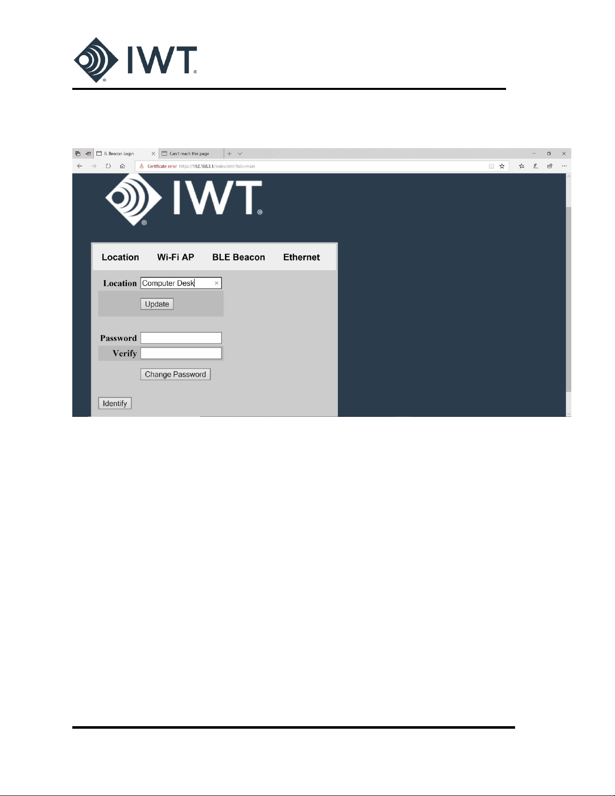
location support for indoor facilities. An internal configuration webpage allows the Wi-Fi and
Bluetooth® parameters to be configured from a laptop/tablet/phone.
2. SAFETY INFORMATION
IMPORTANT! READ BEFORE USING THE INTEGRATED MESH NODE
This section contains important information on the safe operation of the IMN.
2.1 DEVICES INSTALLED ABOVE GROUND
NOTE: FCC CERTIFICATION PENDING
2.1.1 Part 15 of Federal Communications Commission (FCC) Rules Compliance
This device complies with Part 15 of FCC Rules. Operation is subject to the following two conditions:
1. This device may not cause harmful interference.
2. This device must accept any interference received, including interference that may cause
undesired operation.
This device contains FCC ID: 2AJVP-OMEGA2
FCC ID: PENDING
When operated above ground, ILB professional installation is required. No external antennas are
approved for use with this product.
NOTE: This equipment has been tested and found to comply with the limits for a Class B digital device,
pursuant to Part 15 of FCC rules. These limits are designed to provide reasonable protection against
harmful interference in a residential installation. This equipment generates, uses, and can radiate RF
energy which may cause harmful interference to radio communications if not installed and used in
accordance with the instructions. It is important to note that proper installation does not guarantee
interference will not occur. If this equipment does cause harmful interference to radio or television
reception, which can be determined by turning the equipment off and on, the user is encouraged to try
to correct the interference by one or more of the following measures:
reorient or relocate the receiving antenna;

Revised: 11/24/2020 6650-20-0014, Rev. A
Approval: Page 4 of 13
increase the separation between the equipment and receiver;
connect the equipment into an outlet on a circuit different from that to which the receiver is
connected; or
consult the dealer or an experienced radio/TV technician for help.
2.1.2 FCC Allowable Limits for General RF Exposure
CAUTION! To ensure that exposure to RF electromagnetic energy is within the FCC allowable limits for
general RF exposure, always adhere to the following guidelines:
The antennas used for the ILB transmitters must not be co-located or operating in conjunction
with any other antenna or transmitter.
The ILB must be installed 20 cm or more from any personnel in order to comply with FCC
exposure requirements.
2.2 MODIFICATIONS
Changes or modifications to the ILB not expressly approved by Innovative Wireless Technologies, Inc.
may void the user’s authority to operate this equipment.
3. SPECIFICATIONS FOR FAP5030-030
(Typical unless otherwise specified)
PHYSICAL & ENVIORNMENTAL
Operating Temperature
-20C to +60C
Operating Humidity
15 to 95%, non-condensing
Dimensions
5.5”x 4.3” x 2.3”
Weight
1 lb
Enclosure Protection
IP54
Wi-Fi
Bands
2.4 GHz
Standards
802.11 b/g
Beacon Interval
100 msec
Transmit power
20 dBm
BLUETOOTH®
Note: BLE Beacon is disabled in default configuration.
Bands
2402-2480 MHz
Standards
4.0, 4.1, 4.2

Revised: 11/24/2020 6650-20-0014, Rev. A
Approval: Page 5 of 13
Types
iBeacon, Eddystone
Transmit Power
0 dBm
ETHERNET
10/100 Mbps
PoE IEEE 802.3a, class 0
RJ45 interface with PoE support
4. INDOOR LOCATION BEACON DESCRIPTION
To begin using the ILB, review the information below covering the basic information you need to know
to get started.
4.1 INPUTS AND OUTPUTS
The Indoor Location Beacon is shown in Figures 1 and 2.
Figure 1 - Side View of ILB
Status
LED
Wi-Fi
Node ID

Revised: 11/24/2020 6650-20-0014, Rev. A
Approval: Page 6 of 13
Figure 2 - Bottom View of ILB
The following is an explanation of the IMN inputs and outputs as shown in Figure 1:
PoE INPUT: The ILB is powered by PoE. The power input to the ILB is an RJ45 connector on the back
side of the enclosure.
Status LED:The ILB contains a single red/green LED that indicates the status of the device (power
on, identification).
5. CONFIGURING THE ILB
Prior to installation, the ILB may be configured using a laptop/tablet/phone and the ILB’s internal
Configuration Webpage. The default configuration settings are shown in Figures 5 through 8 below.
The device must be powered ON to be configured.
With the device powered on:
1. Click on the wireless network icon in the bottom corner of the laptop screen (or search for
wireless devices on tablet/phone) to view available Wi-Fi networks.
2. Search for the ILB device to be configured. The ILB will appear in the list of wireless networks as
ILBeacon-XXXX where ‘XXXX’ is the four-digit node ID listed on the label of the device. Each ILB
device has a unique ID.
PoE
Input

Revised: 11/24/2020 6650-20-0014, Rev. A
Approval: Page 7 of 13
Figure 3 - Connecting to ILB with device ID 6883 (Wi-Fi)
3. Connect to the ILB. The default network security key is Beacon123. This passphrase may be
changed as part of the configuration process using the ILB Configuration Webpage.
4. When the laptop is successfully connected to the ILB, open the device’s internal Configuration
Webpage by typing the following into a browser (Chrome, Firefox, Microsoft Edge
recommended):
https://192.168.3.1
If a ‘Certificate Error’ message appears, select the option to continue on to the webpage. Figure
4 below shows an example of the Certificate Error page(s) that appear when using Microsoft
Edge as a browser.

Revised: 11/24/2020 6650-20-0014, Rev. A
Approval: Page 8 of 13
Figure 4 - Opening the Configuration Webpage
The ILB Configuration Webpage will open and Login information is requested.
The default Login information for each ILB device is as follows:
username: admin
password: Beacon123

Revised: 11/24/2020 6650-20-0014, Rev. A
Approval: Page 9 of 13
After a successful log-in, the MAIN screen of the Configuration Webpage will appear (Figure 5):
Figure 5 - Main page of the Configuration Webpage (LOCATION tab)
The four tabs on the Configuration Webpage can be used to switch between the different configuration
options. The initial page that appears after logging in is the LOCATION tab. On this screen, the user may
enter a text description of the physical location of each installed ILB device. To add a location
description, type the desired text in the Location box and press the Update button.
The LOCATION tab also includes the option to change the Login password of the device. To change the
password, type a new password into the Password box. Re-type the new password again in the Verify
box and press the Change Password button.
The LOCATION screen also includes an Identify button. Pressing the Identify button will cause the LED
on the connected ILB to blink GREEN for 45 seconds. This feature can be used to quickly identify and
verify which ILB device is being configured if there are a number of devices located or installed in the
same area.
Selecting the WI-FI AP tab opens the window shown in Figure 6. The WI-FI AP screen includes
information necessary to configure the Wi-Fi beacon.

Revised: 11/24/2020 6650-20-0014, Rev. A
Approval: Page 10 of 13
Figure 6 –Wi-Fi AP Configuration Screen
The last four digits of the SSID match the ID of the individual ILB device (labeled on enclosure).
The Passphrase is the network security key used to connect to the device. The default Passphrase for
each ILB is Beacon123. To change the SSID or Wi-Fi Passphrase, enter new values in the text box and
press the Update button at the bottom of the screen. The update may take up to 30 seconds.
The BLE BEACON screen includes information necessary to configure the Bluetooth Low Energy beacon:

Revised: 11/24/2020 6650-20-0014, Rev. A
Approval: Page 11 of 13
Figure 7 - BLE Beacon Configuration Screen
The ILB’s BLE beacon is Disabled by default. To enable the Bluetooth beacon, select the desired Beacon
type (iBeacon or Eddystone) and press the Update button at the bottom of the screen. If the beacon is
not detected, power cycle the device.
The Bluetooth UUID may be changed by entering a new value and pressing the Update button at the
bottom of the screen. Note: The default UUID is the same for all ILBs.
Selecting the ETHERNET tab opens a screen with information pertaining to an Ethernet connection to
the device.

Revised: 11/24/2020 6650-20-0014, Rev. A
Approval: Page 12 of 13
Figure 8 - Ethernet Configuration Screen
If the ILB is connected wirelessly to a laptop/tablet/phone for configuration, the IPv4 Address and
Netmask boxes will indicate ‘None’ as in the figure above.
6. INSTALLATION
IMPORTANT! TRAINED PERSONNEL MUST PROFESSIONALLY INSTALL THE ILB.
6.1 SITE SURVEY
Conduct a survey to determine the appropriate sites to install the ILBs.
6.2 MOUNTING AN ILB
The ILB may be mounted to a wall or ceiling tile using four ‘blind’mounting holes. The mounting holes
are accessed by lifting the flaps on the enclosure lid as shown in Figure 9.

Revised: 11/24/2020 6650-20-0014, Rev. A
Approval: Page 13 of 13
Figure 9 - ILB Mounting holes
An optional aluminum mounting bracket is available for use with the ILB.
Note: The ILB should not be installed in plenum spaces above ceiling tiles.
7. OPERATING AND MAINTENANCE INSTRUCTIONS
7.1 POWERING THE ILB
The ILB is automatically powered ON when a PoE input cable is plugged into the RJ45 connector on the
back of the device. The ILB does not have an ON/OFF switch. Disconnecting the PoE input will remove
power from the device.
7.2 STATUS LEDS
The status of the ILB’s connection to power and the Wi-Fi / Bluetooth network may be monitored by
observing the blink pattern of the indicator LED mounted on the outside of the enclosure:
Solid RED: Device booting when initially powered ON
Solid GREEN: Power on, normal beacon operation
Blinking GREEN: Used to identify the device during configuration (see Section X.X)
7.3 CHANGING THE COFIGURATION OF AN ILB
The configuration of the ILB may be changed using the internal Configuration Webpage described in
Section 5 above. Follow the instructions is Section 5 for connecting to the ILB and opening the
Webpage.
8. WARRANTY INFORMATION
Never disassemble the ILB. Doing so will void your warranty. If an ILB is damaged, do not use it.
Table of contents
Popular Security System manuals by other brands

Pump Alarm
Pump Alarm Cellular Alarm Quick start installation guide

careium
careium Eliza S Technical guide

FireClass
FireClass MCP200CS manual

Emerson
Emerson FA-700 Installation and operation manual

BT Redcare
BT Redcare 3GSTU-12V User's installation guide

SF Detection
SF Detection Z10a OPERATING AND INSTALLATION Manual