IXIA TP-CU3-ZD User manual

TP-CU3-ZD, -DC Gig Zero Delay
Quick Install Guide
913-2114-01 Rev B 1/15
TP-CU3, -DC 10/100/1000BaseT Tap

2
PLEASE READ THESE LEGAL NOTICES CAREFULLY.
Trademarks and Copyrights
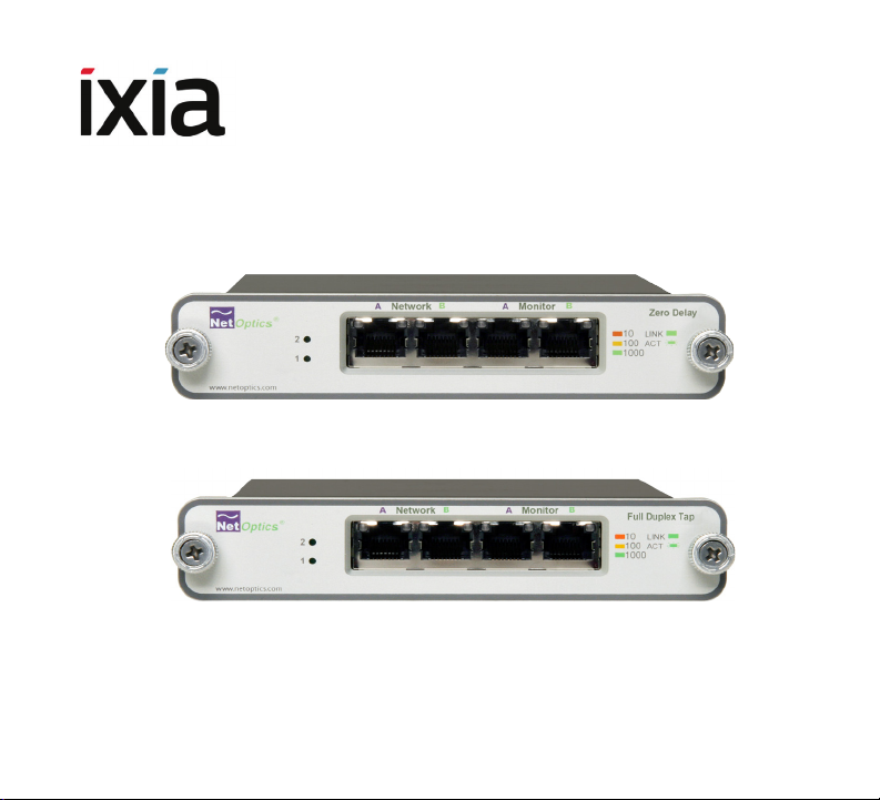
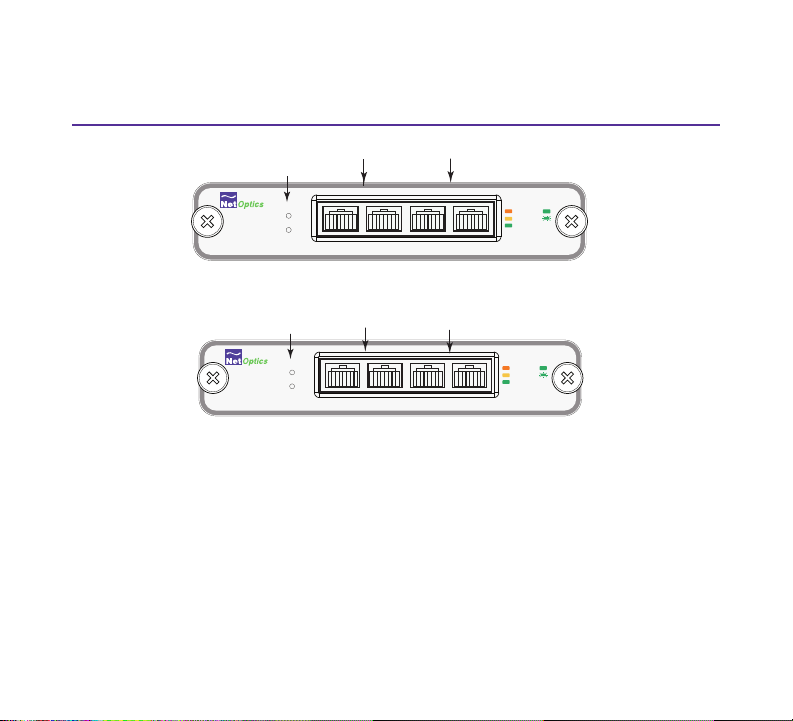
Net Optics is a registered trademark of Net Optics, Inc. By using the TP-CU3 and TP-CU3-ZD taps, you
agree to the terms and conditions of usage set forth by Ixia.
Copyright © 2005-2015 Net Optics, Inc. with modications Copyright © 2015 Ixia. All rights reserved.
This publication may not be copied, in whole or in part, without Ixia’s consent.
RESTRICTED RIGHTS LEGEND: Use, duplication, or disclosure by the U.S. Government is subject
to the restrictions set forth in subparagraph (c)(1)(ii) of the Rights in Technical Data and Computer
Software clause at DFARS 252.227-7013 and FAR 52.227-19.
Ixia, the Ixia logo, and all Ixia brand names and product names in this document are either trademarks
or registered trademarks of Ixia in the United States and/or other countries. All other trademarks
belong to their respective owners.
The information herein is furnished for informational use only, is subject to change by Ixia without
notice, and should not be construed as a commitment by Ixia. Ixia assumes no responsibility or
liability for any errors or inaccuracies contained in this publication.
This product is covered under the Ixia Limited Warranty and Technical Support Agreement. You can
nd this Agreement by going to the following link -- http://www.ixiacom.com/support/warranty/. Click
on the Limited Warranty and Technical Support Agreement link to view the document.

3
Contents
TP-CU3-ZD and TP-CU3 Content 4
TP-CU3-ZD and TP-CU3 Overview 5
Step 1 - Rack Mount Tap 7
Step 2 - Connect AC Power 9
Connect DC Power 10
Step 3 - Congure the DIP Switches 11
Step 4 - Connect to the Network 14
Step 5 - Connect to the Monitoring Devices 15
Support 16

4
TP-CU3-ZD and TP-CU3 Content
This guide provides the initial steps to set up and congure the following Tap models:
• TP-CU3-ZD 10/100/1000 Tap with Zero Delay
• TP-CU3-ZD-DC 10/100/1000 Tap with Zero Delay, -48V DC power
• TP-CU3 10/100/1000 Tap
• TP-CU3-DC 10/100/1000 Tap, -48V DC power
Carefully unpack the Tap and check for damaged or missing parts.
• 2 Power cords and power supplies, 12VDC, 3.3A, 2.5mm, IEC-C13
• 2 Power cords and power supplies, 12VDC, 1.5A, 2.5mm, IEC-C13 (TP-
CU3 only)
• Retainer clip (not included with -DC models)
• 3 CAT 5e 4-pair (purple) cable, 3-meter, RJ45
• 1 CAT 5e 4-pair (green) Crossover cable, 3-meter, RJ45
• Registration card
You may have also ordered a panel for rack mounting and an extended warranty. Check
the packing slip against parts received. If any component is missing or damaged,
contact our Order Management department via email at Order-Management@

5
TP-CU3-ZD and TP-CU3 Overview
Figure 1 - Front Panel, Gig Zero Delay Taps (TP-CU3-ZD, -DC)
Monitor A & B
Network A & B
Power
LEDs
®
www.netoptics.com
Network
10
100
1000
LINK
ACT
1
2
Full Duplex TapFull Duplex Tap
A AB B
Monitor
Figure 2 - Front Panel, 10/100/1000BaseT Taps (TP-CU3, -DC)
LED Indicators
Power Indicator: Current power source LED illuminates white.
Link/Activity Indicator: Located in the upper right corner. If a good link is
established, the LED lights up. The LED ashes when there is activity.
10/100/1000 Indicator:In the upper left corner. The LED is orange when the Port is set
to 10 Mbps . The LED is yellow if the Port is set to 100 Mbps. The LED is green when the
Port is set to 1000 Mbps.
Monitor A & B
Network A & B
Power
LEDs
®
www.netoptics.com
Network Monitor
10
100
1000
LINK
ACT
1
2
Zero DelayZero Delay
A AB B

6
Figure 3 - Rear Panel AC (external transformer “brick”) power models
Figure 4 Rear Panel DC power model TP-CU3-DC
Figure 5- Rear Panel DC power model TP-CU3-ZD-DC
Power DC Jacks
Retainer Clip
DIP Switch
1 3 4 5 6 7 82
- + - +
For use with -48 only
- + - +
Terminal BlocksDIP Switch
1 3 4 5 6 7 82
- + - +
For use with -48 only
- + - +
Terminal Block DIP Switch
on side
Terminal Block

7
Step 1
Rack Mount Tap
If you ordered the rack mounting panel, do the following:
1. Remove the panel and screws from the shipping bag.
2. Screw the panel onto the rack.
3. Slide the switches in place in the rack. See Figure 6.
See Figure 7 if you ordered the 12-Slot version.
4. Fasten the switches in place with the Phillips screws.
Figure 6 - 1U Version

8
Figure 7- Tall 12-Slot Version

9
Step 2
Connect AC Power
Ensure the Tap is grounded before connecting power. Do the following to connect
and apply power to the AC powered tap:
1. Plug one of the supplied power cords to a power connector located at the rear
of the chassis. Plug the other end to a power source. See Figure 8.
2. For redundancy, plug the other power cord to the other connector. Plug the
other end to a source independent from the rst power source.
The second power supply is available to support the ow of trafc to the
monitoring device in the event that the rst power supply becomes
unavailable.
3. Verify the Power LEDs on the front illuminate.
Figure 8 - Power Connections
Power DC Jacks
Retainer Clip
DIP Switch
1 3 4 5 6 7 82

10
Connect DC Power
Model TP-CU3-DC has screwless terminal blocks for DC power. Push in the orange
button to open the socket, insert the power wire, and release the button to clamp the
wire into the socket.
Model TP-CU3-ZD-DC has a two-piece, screw-type terminal blocks for DC power. You
can unplug half of the terminal block for convenience when connecting the power
wires. Just pull to unplug the removable part, and push it back in to reconnect it. To
connect the power wires, insert a wire into a socket and tighten the screw to hold it in
place.
Figure 9 - Two-piece DC terminal block on model TP-CU3-ZD-DC
Note: The symbols and both indicate safety ground, also called earth
or chassis ground. When attaching the DC power wires, always connect the safety
grounds rst; and when disconnecting the DC power wires, always disconnect the
safety grounds last.

11
Step 3
Congure the DIP Switches
The 8-position DIP switch located on the rear panel or on the side of the device sets
the communication parameters and battery connection as specied in the following
table.
Note: The settings apply to all ports on the Tap (except for Switch 1, Link Fault Detect,
which applies only to the Network Ports).
If you use xed settings, connected devices must match the settings you select for the
Tap. If you use Auto-negotiation ON, make sure the network devices connected to the
Tap are set to Auto-negotiation ON.
1 3 4 5 6 7 82
ON
LINK
FAULT
DETECT
ON
OFF
ON
OFF
ON
OFF
ON
OFF
FD
HD
ON
OFF
ON
OFF
10
100
1000
ON
OFF
RESV
DUPLEX
AUTO
NEGOTIATION
BATTERY
Figure 10 - DIP Switch Settings

12
Switch Position Description
1 ON
OFF
Link Fault Detect (LFD) is active on the Network Ports.
Link Fault Detect (LFD) is inactive on the Network Ports.
2-5 See following table
6ON
OFF
All ports are in Full-duplex mode.
All ports are in Half-duplex.
If switch 2 is ON, this switch is ignored
7- Reserved
8
ON
OFF
Up position. The backup battery is not connected.
Down position. The backup battery is connected. The unit is
shipped with this switch in the down position.
2 3 4 5 Line speed for all ports
ON XX X Auto-negotiation
OFF ON X X 1000BaseT (Gigabit)
OFF OFF ON X 100BaseT (100Mbps)
OFF OFF OFF ON 10BaseT (10Mbps)
OFF OFF OFF OFF DO NOT USE
* ON = up position OFF=down position

13
IMPORTANT NOTES:
• The Tap is shipped with switches 1 and 2 in the ON position (LFD and Auto-
negotiation active).
• If you are using a xed-speed setting, all devices connected to the Tap should
also be set to that same speed. Furthermore, you should set only one speed
switch to ON (up position). If more than one speed switch is set to ON, the Tap
uses the fastest speed.
• When the unit is shipped, dip switch 8 is set to the down position. After you
connect power, make sure the power is ON for 12 hours to fully charge the
backup battery. In the event of a power outage, the Zero Delay Tap can remain
powered for 3 to 5 hours with a fully charged battery.
• If you plan to store or power down this unit for longer than 2 hours, follow this
procedure:
Step 1 - Set the dip switch 8 to the up position.
Step 2 - Disconnect all power sources.
Step 3 - When the power sources have been disconnected, set dip
switch 8 to the down position.
Step 4 - Store the unit.
• When you redeploy the unit, ensure dip switch 8 is in the down position. Then
connect to the power source.

14
Step 4
Connect to the Network
To connect the Tap to the Network:
1. Connect Network Port A to the appropriate switch, server or router using one of
the supplied purple CAT5e cables.
2. Connect Network Port B to the appropriate switch, server or router using one of
the supplied purple CAT5e cables.
3. Verify that the Tap Network Ports are cabled in-line between two devices
4. Verify the link LEDs illuminate.
Figure 11 - Connecting to the Network
®
www.netoptics.com
Monitor
Network
10
100
1000
LINK
ACT
1
2
Full Duplex TapFull Duplex Tap
A AB B
To switch, server or router To switch, server or router

15
Step 5
Connect to the Monitoring Devices
To connect the Tap to the Monitoring device:
1. Connect Monitor Port A to the appropriate port on the monitoring device using
one of the supplied purple CAT5e cables.
2. Connect Monitor Port B to the appropriate port on the monitoring device using
one of the supplied purple CAT5e cables.
Figure 12: Connecting to the Monitoring Device
®
www.netoptics.com
Monitor
Network
10
100
1000
LINK
ACT
1
2
Full Duplex TapFull Duplex Tap
A AB B
To monitor NIC
To monitor NIC

16
Support
If you have questions while your product is under warranty or you are enrolled in a
support plan, please contact one of Ixia’s Technical Assistance Centers (TACs) by
phone or e-mail.
Taiwan/Hong Kong:
or visit www.ixiacom.com/support.
www.ixiacom.com
Copyright © 2005-2015 Net Optics, Inc.
with modications Copyright © 2015 Ixia. All rights reserved.
This manual suits for next models
3
Table of contents