J D Squared 4 Quick reference guide

Mo d e l 4 Tu b e be n d e r
Assembly & Operating Instructions
J D Squared Inc.
2244 Eddie Williams Rd. Johnson City, TN 37601
(423) 979-0309, FAX (423) 979-2426
Internet: www.jd2.com
© Copyright 2008 by J D Squared Inc.
Revision 4 (7/10/2008)

Unpacking & Parts List
The basic Model 4 bender is shipped in 2 packages. Package 1 contains the lower frame only. Package
2 contains all other parts needed for assembly, excluding the hydraulic cylinder, pump and hose. If these
items were also ordered with the bender, they will arrive in their own separate boxes. Upon receiving
both packages verify that neither package shows any signs of damage and that all parts are present. If
a package has been damaged and parts are either missing or damaged, you must immediately contact
our sales ofce.
PACKAGE 1 CONTENTS:
1 Lower frame
PACKAGE 2 CONTENTS:
1 Instruction manual
------------------------------
1 Upper frame
11 3/4" S.A.E. washers
3 3/4" x 2" at head screws
3 3/4" nuts
3 1 1/2" diameter frame sleeves
3 1" x 8" bolts
6 1" S.A.E. washers
3 1" nuts
1 1" x 8" diameter frame pin
2 7/8" x 8" frame link pins
------------------------------
1 7/8" x 6 1/4" drive link pins
1 Drive link - Lower
1 Drive link - Upper
1 3/4"-16 x 5" long bolt (Outside drive link bolt)
1 3/4"-16 x 4 1/2" long bolt (Inside drive link bolt)
2 1" diameter drive link sleeves
1 Hydraulic swivel block
------------------------------
1 Pusher block with 1" diameter ange bolt welded in place
1 Pusher block handle
1 3/16" x 1 1/4" long roll pin
1 1 1/2" diameter pushrod (screws into hydraulic cylinder)
1 Bronze pivot block
2 1/2" diameter shoulder bolts
1 3/8" nylock nut
1 Anti-Springback lever
1 1/2"-20 x 1" long bolt
1 1/2" S.A.E. washer
1 3/4" diameter x 3/8" long sleeve (for anti-springback lever)
1 1/2" threaded spring pin
1 1/2"-20 ne thread nut (will be installed on spring pin)
1 spring
1 1/4" x 1 1/2" long socket head bolt
2 1/4" nuts
- 1 -

Assembly
1) The bender may be mounted to anything rigid enough not to twist or move
during the bending operation. To mount the bender, drill three 3/4" holes through
your mounting surface. You can use the frame holes as a guide. Place two 3/4"
washers on the top of each drilled hole. These washers will act as spacers to insure
that the bender pins, when installed, will be completely pass through the lower
frame holes. If you purchased the optional pedestal, position the washers over the
slots as shown in gure 1.
3) Remove the 1" frame pin. Locate the lower drive link. It will
have two 3/4" tapped holes in it and a recess milled out of its
bottom side's center. Place it on the lower frame with its inside 1"
hole over the lower frame's 1" center hole and its milled recess
facing down. Replace the 1" frame pin. Locate the hydraulic
cylinder's swivel block. Examining the swivel block you will see
the word 'TOP' stamped into it. Insert the swivel block into the
lower drive link's remaining 1" hole. Your Model 4 should now
look like gure 3.
2) Refer to gure 2. Using three 3/4" x 2" long at head
bolts, three 3/4" nuts and three 3/4" washers, tightly
securetheframetoyourmountingsurface/pedestal. Using
three 1 1/2" diameter frame sleeves, three 1" diameter
x 8" long bolts, six 1" washers and three 1" nuts, install
the upper frame onto the lower frame. Lightly tighten the
bolts. Next install the 1" frame pin as shown in gure 2.
Using a small square placed against the 1" pin, move
the upper frame around until the frame pin is perfectly
vertical. Tighten all three 1" bolts.
4) Refer to gure 4 for this step. Remove the 1" frame pin. Locate the
upper drive link. Place it in the bender so that it aligns with the lower
drive link and engages the swivel block's upper shaft. Reinstall the 1"
frame pin. Place the two 1" diameter drive link sleeves between the two
drive links aligned with the 3/4" holes. Place a 3/4" washer onto the
3/4"-20 x 5" long bolt. Install it into the outside 3/4" sleeve and lightly
tighten. Place a 3/4" washer onto the 3/4"-20 x 4 1/2" long bolt. Install
it into the inside 3/4" sleeve and tighten securely. Remove the whole
drive link assembly and turn upside down. Look on the bottom side
of the lower link and verify that the inside 3/4" bolt threads do NOT
protrude out of the link. If it does, it will severely scratch the frame's
machined surface. Also the bender's links will not ride properly on the
lower frame. The only way this should be able to occur would be if the
longer 5" bolt was installed where the 4 1/2" bolt should be.
- 2 -
Figure 3
Figure 1
Figure 2 - Upper frame installed
Figure 4 - Drive links installed
Upper Frame Link
Lower Drive Link
Hydraulic
Swivel
Block

5) Invert the drive link assembly as shown in gure 7.
Locate the parts listed below:
1 Anti-Springback lever
1 1/2"-20 x 1" long bolt
1 1/2" S.A.E. washer
1 3/4" diameter x 3/8" long sleeve
1 1/2" threaded spring pin
1 1/2"-20 ne thread nut
1 1/4" x 2" long socket head bolt
2 1/4" nuts
1 Spring
Place the 1/2" washer onto the 1/2"-20 x 1" long bolt.
Next place the 3/4" diameter sleeve onto the bolt also. This
sleeve acts as a spacer. Study gures 5 and 7 carefully and
then position the anti-springback lever as shown. Install the
bolt, washer and sleeve through the anti-springback lever
and into the lower drive link. Tighten securely. Verify that
the lever rotates freely.
Install the 1/2"-20 ne thread nut onto the spring pin
about half way up. Install the spring onto the spring pin as
shown in gure 6. Screw the spring pin into the lower link
until it starts to protrude out the other side of the drive link.
Back it off 1 to 2 turns, to make sure it doesn't protrude,
and tighten the 1/2" nut.
Install a 1/4" nut onto the 1/4" x 2" long socket head
bolt. Adjust the 1/4" nut so that when the bolt is installed in
the anti-springback lever, the 1/4" nut on the other side of
the anti-springback lever can be completely installed with
only 1 thread visible. This will put the bolt's head roughly
even with the spring pin's head. Remove the 1/4" bolt. Being
careful not to turn the 1/4" nut already installed, insert the
bolt's head through the open loop of the spring. Holding
the bolt, stretch the spring and insert the bolt back into the
1/4" hole in the anti-springback lever. Install the other 1/4"
nut onto the bolt from the top side of the anti-springback
lever and tighten. Remember that only one thread of the 1/4"
bolt should be visible from the top side of the anti-springback lever. Figures 6 and 7 show the complete
assembly correctly installed. Note that the outside 3/4" bolt protrudes out of the bottom of the lower drive
link and that the inside 3/4" bolt does NOT.
Install the completed drive link assembly into the bender. The easiest way to do this is from the rear of the
bender. Insert the drive link assembly with
the open 1" holes between the 1" holes in the
frame.Insertthe1"framepin.Nowrotatethe
drive link assembly counterclockwise until it
rest on the machined upper surface of the
frame. If it does lay at, the upper frame link
will need to be loosened and repositioned
until the 1" frame pin is perfectly vertical.
Rotate assembly until the degree scale
reads 30 to 60 degrees on the right side
of the lower drive link.
- 3 -
Figure 5 - Anti-springback lever
Figure 6 - Spring installation
Figure 8
Figure 7 - Lever system installed
Spring Pin1/4" Bolt
Anti-Springback
lever

6) Locate the parts shown in gure 9 and listed
below:
1 Pusher Block
1 Pusher Block Handle
1 Bronze Pivot Block
1 Pushrod (1 1/2" diameter)
2 1/2" x 2 1/2" long shoulder bolts
1 3/16" roll pin
1 3/8" nylock nut
1 1" diameter welded ange bolt
NOTE: This bolt is shown as a seperate
itemingure9foreasieridentication.
However,Ithasalreadybeenweldedinto
thePusherBlock.
Examine the bronze pivot block.You will notice
that the 1/2" hole has been offset drilled to one
side as shown in gure 10. The distance from
the hole's edge to the pivot block's side will be
less than the other three sides. This is the pivot
block's upper side. Now examine the pusher
block. You will see a 1 1/2" slot milled completely
through its top surface and on its bottom you will
see a smaller recess milled into it's front edge.
Note: The pusher block shown in gure 9 is bottom side up so that
the milled recess can be clearly seen. This recessed area is where
the bronze pivot block is installed. Hold the pusher block so that the
engraving on its side is right side up and facing you. Position the
bronze pivot block into the lower recess so that its upper surface is
facing up (the hole is offset to the top). From the engraved side of
the pusher block, insert one of the two 1/2" shoulder bolt and secure
tightly with the 3/8" nylock nut. When completed it should look like
gure 11. The pivot block must also be protruding out of the bottom
of the pusher block approximately 1/16" as shown in gure 12. If it's
not, it's installed wrong and must be reinstalled.
As shown in gure 13, position the pushrod into the pusher block's
upper slot. The 1/2" hole in the pushrod nearest to the end should be
lined up with the 1/2" hole in the pusher block. Insert a 1/2" shoulder
bolt into the pusher block from the side opposite the engraving. Install
the pusher block handle onto this shoulder bolt and tighten. Lay the
pusher block down on the side opposite the engraving. Slightly rotate
the pushrod so that the 1/2" hole in its middle is under the 3/16" hole
drilled into the engraved side of the pusher block. Being careful not to
mar the engraved face of the pusher block, hammer in the 3/16" roll
pin until it is ush with the pusher block's surface. Figure 11 shows
this step completed.
- 4 -
Figure 9 - Pusher assembly
Figure 10
Figure 12
Figure 11 - Pusher block
Figure 13
Pusher assembly complete
Bronze Pivot
Block Upper Side
Pushrod
1" Welded
Flange Bolt
Pusher Block Handle
Pusher Block
Bronze Pivot Block

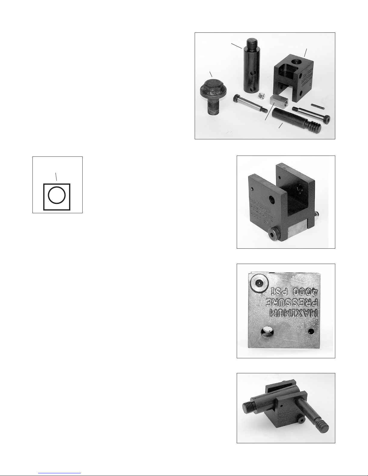
7) Screw the hydraulic cylinder completely into the hydraulic
swivel block. If when tightened the cylinder's quick disconnect
hose tting is not facing in the downward direction, loosen
the cylinder until it does face in the downward direction. The
cylinder will have a little play in its threads. This is normal and
will not cause any problems.
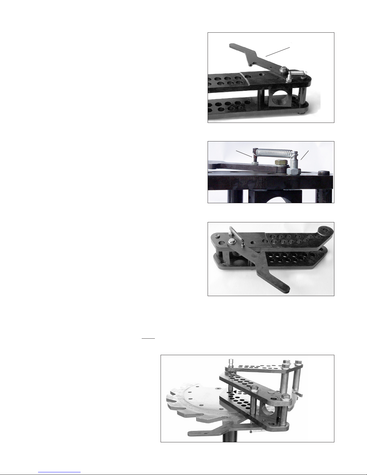
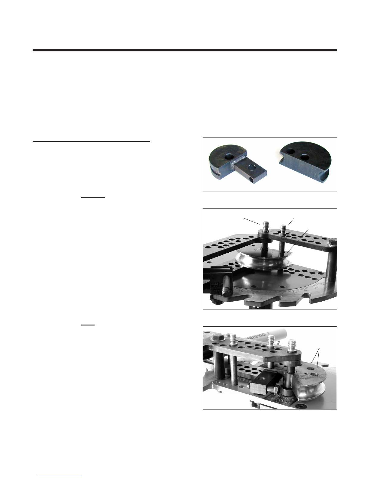
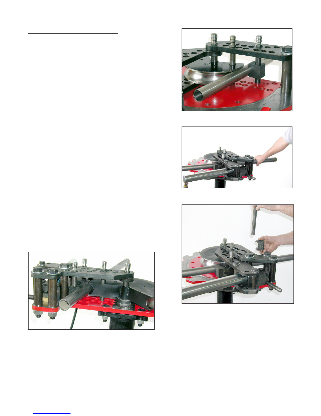
Screw the completed pusher block assembly into the
cylinder. You may need to rotate the drive links to the rear
of the bender in order for the handle to clear the main frame
as the pusher block is screwed into the cylinder. Rotate the
pusher block so that the handle is facing toward you. Rotate
the drive links until the pusher block is positioned approximately
as shown in gure 14.
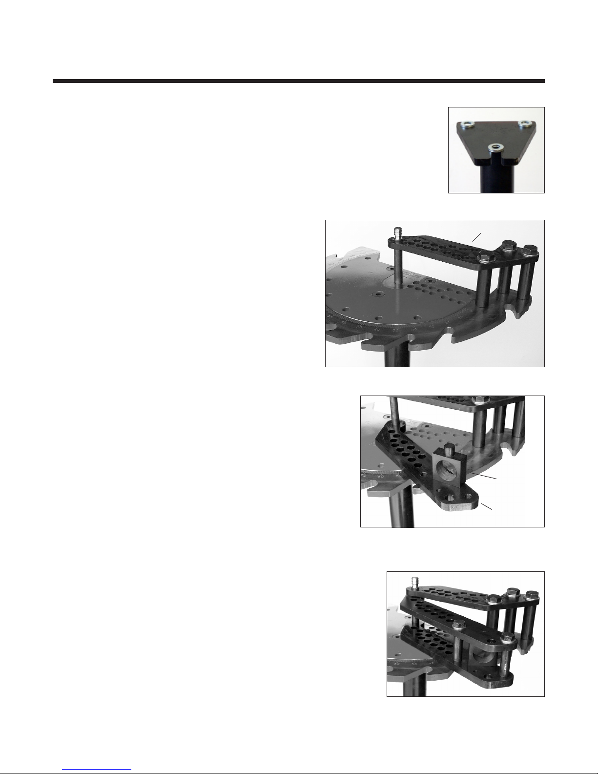
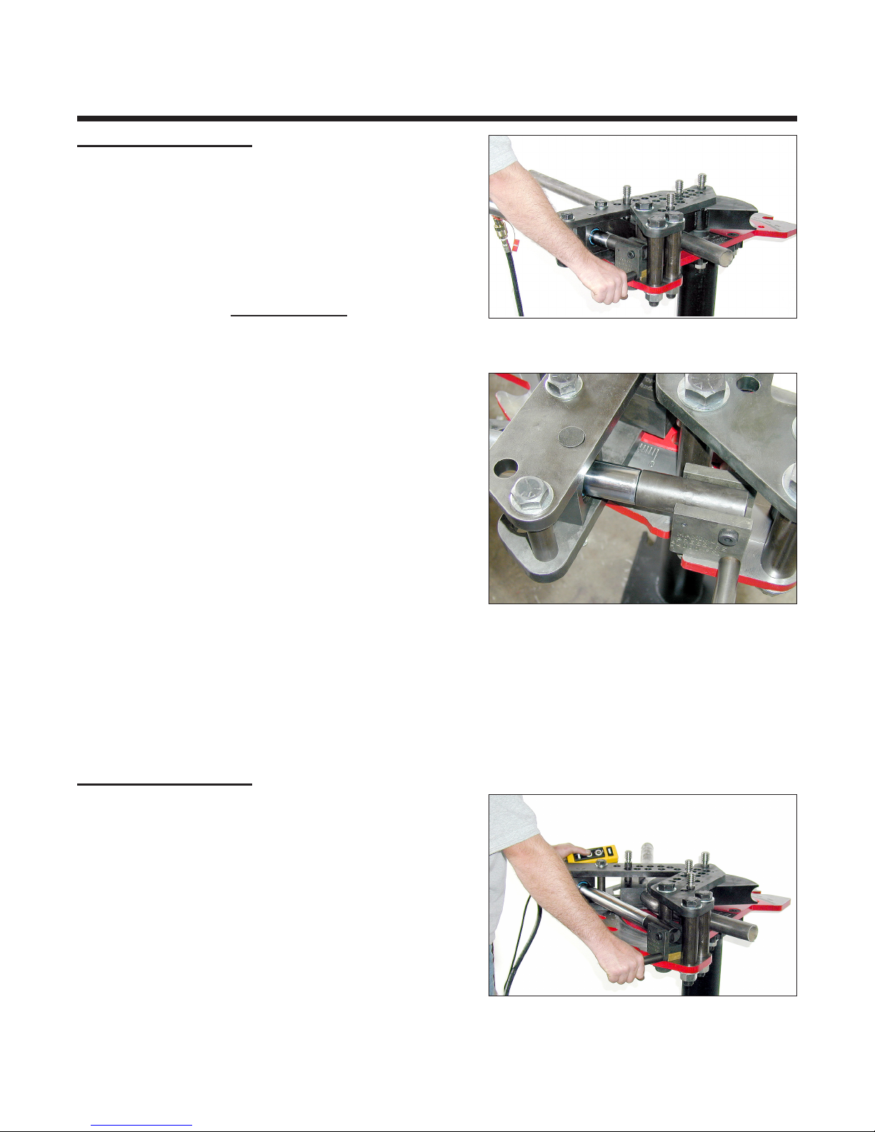
Using the handle, move the 1" welded ange bolt into
one of the lower frame's teeth. When the bender is under load, the rear of the pusher blockshould rise
approximatley 1/16" above the face milled at of the lower frame. With the bronze pivot block protruding
out of the bottom of the pusher block 1/16", this should make the pusher block ride at when bending.
This will eliminate any side loads on the hydraulic cylinder, therefore preventing any unnecessary wear
in the cylinder.
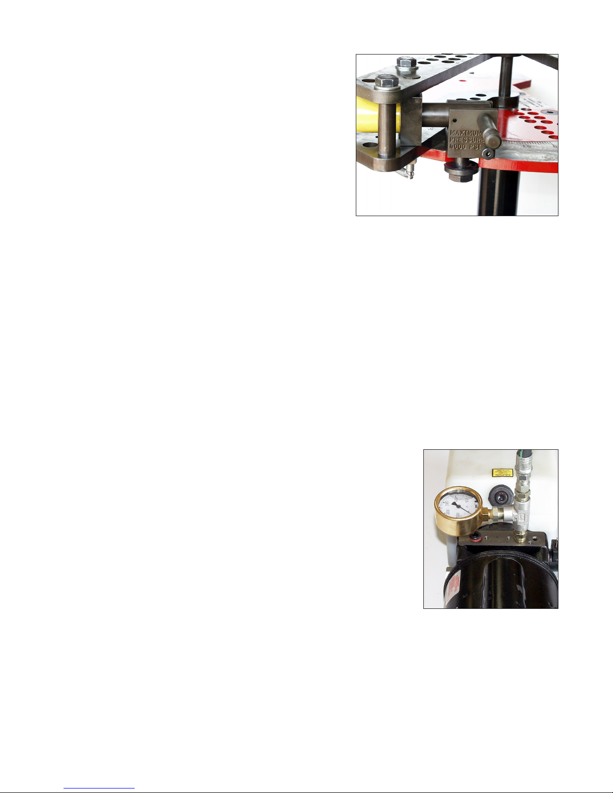
8) Next attach the hose to the pump in its correct port. If you have your own pump or purchased a
pump with your bender and it wasn't the 2 HP model, follow the directions included with the pump. If you
purchased the preferred 2 HP pump as shown in gure 15, you can look at the photo as a reference. Wrap
2 to 3 layers of teon tape around the male threads on the hydraulic hose. Looking at the bender from
the electric motor side, screw the hose into the right side upper port. Wrap 2 to 3 layers of teon tape
around the 1/2" pipe plug and screw it into the left side upper port. Make sure both are tightened snugly.
Attach the hose to the cylinder's quick disconnect tting and hand tighten only. Plug the pump into the
proper electrical outlet. Note: Upon start up, if the pump acts like it's not getting enough current, take these
steps to x the problem. First use a heavy gauge (12 gauge or heavier),
short electrical extension cord. The shorter the better. If using 110 volts,
make sure the electrical circuit breaker is rated at least 30 amps. As a
general rule, if when the bender is operating, the electrical extension cord
feels hot, it's too small. Also if the electrical relay operates erratically when
pressed, it's probably a sign of an electrical supply problem.
Pressing the pump control buttons will extend the cylinder under
pressure or release the pressure, thereby retracting the cylinder using its
internal spring return. If neither button is pressed the cylinder will hold its
position. The 2 HP pump is relatively fast. It's easy to overshoot the desired
bend angle. To prevent this from happening, follow this procedure: Press
the cylinder extend button and hold down until the bender is 3-5 degrees
before the desired angle. Now quickly tap the button on and off until the
bender edges up to the proper degree. With practice you should easily be
able to advance the cylinder as little as 1/5 of a degree. Note the 5000 p.s.i.
pressure gauge shown in gure 15. This gauge is not included with the pump, but is highly recommended.
A good quality gauge can be purchased at any hydraulic supply business. Simply tee it into the pressure
hose as shown in gure 15.
- 5 -
Figure 14 - Pusher block engaged
Figure 15

- 6 -
Installing Die Sets
The Model 4 bender comes with 4 pins. Locate the pins listed below:
1 1" Diameter x 8" Frame Pin
2 7/8" Diameter x 8" Long Frame Pins (Long Pin)
1 7/8" Diameter x 6 1/4" Long Drive Pin (Short Pin)
A Die Set consists of the 3 parts listed below:
1 Forming Die (Circular in shape, usually with a groove)
1 Pressure Die (The part that slides along the workpiece)
1 U-Block (A small square block that retains the workpiece, also usually has a groove)
STEP 1 - INSTALL THE FORMING DIE
Forming Die Installation
There are two styles of forming dies. One has a
square block welded to its backside as shown in left side
of gure 17. The other doesn't as shown in right side of
gure 17. The method of die installation depends on what
style you have.
Installing a Die without a welded block:
Using the 1" frame pin, place the forming die into the
bender with its rounded side forward as shown in gure
18. The forming die will normally only have one other hole
drilled through it, as shown on the right side of gure 17.
This hole is very close to the die's edge, usually within
a 1/8"-1/4". If there is more than one hole, use the hole
closest to the die's edge. Model 1, 2 and 3 die sets will
work in the Model 4, however they usually will have 3 to 5
holes drilled through them. So with those dies you would
only use the hole closest to the at side of the die.
Rotate the die until the hole in the die lines up with
one of the NUMBERED holes 1 - 4 in the frame (not the
lettered holes). Insert one of the two long 7/8" frame pins
through the frame and die. This pin will prevent the die
from rotating when the bender is operating.
Installing a Die with the welded block:
Using the 1" frame pin, place the forming die into the
bender as shown in gure 19 with the welded block closest
to the frame bolts. The die shown has multiple drive holes
drilled in it. Only the one closest to the die's at side (it
will be the one nearest to the welded block) needs to be
used. A long 7/8" frame pin has been installed in the hole
closest to the dies welded block. Installed this way the
welded block serves no function. This would be the case
if a Model 3 die set was being used in the Model 4.
If the forming die does NOT have any drive holes,
only a welded block, then install the die as shown but
do not use a 7/8" pin. In this case, when the bender is
operating, the welded block on the die will rotate clockwise and contact the workpiece, thus preventing
the die from rotating. Note that if the die has a welded block and drilled drive holes you can use either the
welded block or the rst drive hole.
Drive Holes
Figure 16 - Die styles
Forming Die
1" Frame Pin 7/8" Frame Pin
Figure 17 - Die installed
Figure 18 - Die with welded block

Figure 20 - Top view drawing
Angled Groove
Straight Groove
STEP 2 - INSTALL THE PRESSURE DIE
Pressure Die Installation
Pressure dies are machined to exacting standards and must be installed in the proper orientation.
Depending on whether the die set is for pipe, round or square tubing follow the appropriate directions
below.
ROUND TUBING OR PIPE
The pressure die is shown in gure 19. For round tubing and pipe, the pressure die will have two circular
grooves machined on each end, a leading and a trailing groove. The trailing side groove is machined at
an angle. This angled groove provides better control of the workpiece than a straight groove, resulting
in a better bend quality. However, the pressure die MUST be installed in the bender's drive links with the
angled groove closest to the forming die. If the pressure die is installed upside down, that is with the angled
groove forward, it will try to dig into the workpiece and bend quality will suffer.
Engraved into the pressure die will be the O.D. size of the tubing or pipe and the correct hole number
that it should be installed into the drive links with.
Referring to gures 21 and 22. After the forming die
has been installed, rotate the drive links counter-clockwise
until they are parallel with the upper frame link. Place the
tubing or pipe to be bent through the middle of the drive
links as shown. Next place the pressure die between the
drive links with the angled groove closest to the forming
die. The angled groove should now be towards the rear of
the bender and on your right side. Insert a short 7/8" pin
through the drive links and the pressure die in the exact
hole number engraved into the pressure die.
NOTE:Theangledgroovesupportsthetubeduringthe
bending process, thereby preventing it from excessively
attening on the outside. Never install the pressure die
upside-downwiththeangledgroovenotatthepointofbend
(closesttotheformingdie).Itcandamagethepressuredie
andseverelygougeyourtubeorpipe.Also,ifthepressure
dieisplacedinahole#otherthantheonemarkedonit,
bendqualitywillsuffer.Ifthetubeorpipeisatteningalarge
amountontheoutside,checktomakesurethepressure
dieisinstalledinthecorrectdrivelinkhole.
- 7 -
Figure 19 - Tube or pipe Pressure Die
Figure 22 - Pressure Die installed - back
Figure 21 - Pressure Die installed - front
Straight Groove Angled Groove
Angled Groove towards
back of bender
Straight Groove

STEP 3 - INSTALL THE U-BLOCK
Shown in gure 23 is the U-Block installed in the bender.
Normally the pressure die would have already been installed,
but for a clearer view of the u-block it has been removed.
Looking at the top of the upper frame you will see two
rows of 7/8" holes with letters or numbers beside them. The
front seven row holes (1,2,3,4,E,F,G) are in a straight line
and the back seven holes (A,B,C,D,5,6,7) are staggered.
The back side holes are the ones where the U-Block pin is
normally installed as shown in gure 23.
PROCEDURE:
The forming die, pressure die and workpiece (tube
or pipe) have already been installed in the bender in the
previous two steps.
Position the workpiece where you want it bent. Referring
to gure 24, push the workpiece away from you rmly. This
will seat the workpiece in between the forming die and
pressure die, removing any play.
- 8 -
Install the u-block and long 7/8" frame pin into one of the
7/8" back side holes AS CLOSE TO THE 1" FRAME PINAS
POSSIBLE. This is why you had to push the workpiece away
from you. Figure 26 shows the complete die set installed
as seen from the back side of the bender.
SQUARE TUBING
Square tube die sets are installed in the same way as round tube die sets with the exception of the
pressure die. Square tube pressure dies do not have an angled groove, just one long straight groove.
Therefore, all you need to do is install it in the correct hole# as marked on it.
Figure 23 - U-block installed
Figure 24 - Pushing workpiece
Figure 25 - Installing pin in back hole
Figure 26 - Die set installed as seen from back
side of bender

Operation
STEP 1 - Figure 27 & 28
Using your hands, rotate the drive links clockwise until
the workpiece is rmly seated in the die set with no play.
With the cylinder fully retracted, extend the cylinder while
guiding the pusher block into the rst ratchet tooth on the
frame. DO NOT PLACE YOUR HANDS ANYWHERE ON
THE PUSHER BLOCK EXCEPT ON THE HANDLE. THIS
WILLPREVENTANYPOSSIBLE PINCH POINT.ALWAYS
KEEP YOUR HANDS OUTBOARD OF THE BENDER
WHEN OPERATING. BE CAREFUL!!!
Extend the cylinder lightly until the workpiece is securely
seated in the die set but has NOT started to bend. Look
on the lower rightside of the lower drive link and note the
degree reading as shown in gure 28. Two to eight degrees
is normal, but may vary. This initial degree reading is called
the lead-in angle. You need to add 3 angles together in
order to obtain a correct bend angle.
1) The lead-in angle. This accounts for the bender
and die set clearances.
2) The desired bend angle. This is the actual angle
of bend you want the nished bend to be.
3) Thespringbackangle.Allworkpieceswillspringback
when pressure is removed after bending. Usually
on the order of 2-8 degrees, depending on the
yield strength of the workpiece and the amount
of bend. A tube that springs back 3 degrees at 90
degrees of bend may spring back 5-6 degrees at
180 degrees of bend. The only way to determine
springback values is by trial and error. Once you know the correct values for a specic workpiece
(material, wall thickness, angle of bend) write it down so you can use the same value next time.
Lead-In+Desiredbendangle+Springbackangle=Degreereadingonbenderwhennished
STEP 2 - Figure 29 & 30
Engage the anti-springback lever by pushing it in
towards the frame teeth. While watching the degree
markings on the bender start extending the cylinder. If
making a bend over 55 degrees go ahead and quickly stroke
out the cylinder until around 50 degrees or so. Just before
the anti-springback lever engages the frame's ratchet teeth
stop the cylinder. Try to stop it as close as you can without
the anti-springback lever actually clicking into the frame
tooth. Now rapidly tap the cylinder extend button until the
anti-springback lever engages the frame tooth. You do not
want to go too far, because that would defeat the purpose
of the lever. You want to be able to retract the ram with as
little springback as possible. Refer to gure 30.
-9-
Figure 27 - Engaging 1st ratchet tooth
Figure 29 - Ram extended
Figure 28 - Lead-in degree reading

A QUICK EXAMPLE BEND
As an example, let's say you want to bend a piece of 1 1/4" schedule 40 pipe 90 degrees. Place a
mark on the pipe where you want the bend to start. Install the pipe and the die set into the bender. Position
the mark on the pipe at the point on the forming die where the bend will start. Engage the rst tooth and
preload the pipe by lightly extending the ram. As shown in gure 28, note the lead-in angle. Let's say it
shows 4 degrees. For this size pipe, a springback angle of 3-4 degrees is normal is average. So let's use
3 1/2 degrees. Now add up the 3 degree values.
4 degrees of lead-in angle
90 degrees of desired bend angle
3 1/2 degrees of springback
97 1/2 Degrees total
Extend the ram out until the degree reading is over 50 degrees and just before the lever engages stop
the ram. Quickly tap the ram extend button until the anti-springback lever fully engages, but just barely.
Retract and reengage the ram as shown in gure 32. Continue bending until around 95-96 degrees and
stop. Quickly tap the button until the degree reading is 97 1/2. Disengage the lever and remove the nished
pipe.
STEP 3 - Figure 31
Fully retract the hydraulic ram as shown in gure 31.
STEP 4 - Figure 32
Engage the next tooth and continue.The second stroke
of the ram will take the bend to over 90 degrees. Bends of
120 - 130 degrees will generally require another stroke.
- 10 -
Figure 30 - Lever engaged
Figure 31 - Retracting cylinder
Figure 32 - Engaging next tooth

Learning the operation of a bender is fairly easy. The real challenge is accurately placing the tubing
into the bender so that the bend comes out in the right position. This short tutorial explains the simple
process of template bending.
Make a sample bend called the Template as shown in Figure 33. A permanent mark scribed on the
template allows you to measure and visualize where the bend should be placed in the tubing. Once bent
the tubing will spring out to a larger radius than the forming
die’s size indicates. The larger the O.D. or the stronger
the tubing, the greater the springback. For instance,
chromemoly tubing will springback roughly twice as far
as the exact same size and wall thickness of welded seam
mild steel tubing. By using a template bend with the same
kind of tubing you are going to bend, you do not have to
worry about this springback because the template has
already sprung out to its n ished size.
You may ask if buying bending software is a good
idea. I believe bending software can only jus tied for two
reasons:Creatingpartdrawingsifthesoftwaresupportsthat
function and for setting up a fully automatic CNC bender
for the initial test of a part with multiple bends. Even using
the software the bend locations usually need to be hand
tweaked for accuracy before going into production. Most
professional fabricators use a method similar to what is
described here. It is extremely easy, accurate and fast.
However, what if you need to bend 500 pieces. How would
you use this process? Don’t worry, it’s a simple technique
that I will explain later but rst let’s just complete a single
piece job. To do this I’m going to go through the whole
process that I use to make a four bend rollbar for a racecar
as shown in Figure 34. This is a great example because it’s
a common request, there are no simple 90 de gree bends,
and it is generally a one-off piece. So hold on to your lug
nuts, here we go.
- 11 -
First, you need to make a template. For our example,
we are going to use 1 1/2” o.d. x .120” wall welded seam
mild steel tubing. As shown in Figure 15, the template is a
piece of tubing bent to 90 degrees with approximately 6”
of straight tubing on each side of the bend. Cut a piece of
tubing roughly 30” long. Next, scribe an accurate line all
the way around this tubing 6” from the end. An accurate
and easy way to do this is to use an inexpensive pipe
cutter. Your local home supply store should carry them in
the plumbing department. A small lathe with a sharp cutter
also does a good job. Scribe the line deep enough, roughly
.015”, so that when you paint the template, the line is still
clearly visible. Hand scribing this line is dif cult and not rec-
ommended. The tube should now resemble Figure 35.
Bending Method #1 - Using Template Bends
The Easy Way To Position Bends
Figure 33 - Sample Template Bend
Let’s Make A Bend Template...
Figure 34
Sample Rollbar
Figure 35
Template Line

Load this tube into your bender as shown in
Figure 36. Note that only the die set and tubing
are visible in the gure. The actual bender and
the die set’s u-strap are not shown so that you
can see what we’re trying to achieve. Place the
scribed line at the at edge of the forming die.
Never use the followbar as a reference. If the
forming die has a lock bolt on it, use it to securely
tighten the tubing in place. It’s very important
that this mark stays in line with the die’s at
edge during the bending process or template
will not give you accurate results later.
Figure 36 - Tube positioned
in forming die Template Line
Followbar
Forming Die
Figure 37
As shown in Figure 38, the rollbar will be 40” tall from the oor to its UPPER side. It will be 62” wide
outside to outside. The top two bends are 70oeach and the two lower bends are 20oeach. I recommend
that you purchase an adjustable carpenter's protractor to help determine the degree of bend for your
specic job. They are made of clear plastic and have legs approximately 12” long.
To determine the total length of
tubing needed, you could sit down
and calculate it. This is described in
the next section "Bending Method #2"
which presents a more mathematical
method to bend tubing. However, for
this application, I think it’s a waste of
time.Timeusuallycostmore thantubing,
so here’s the fast way: Take the total
width of the rollbar (62”) and add it to
twice the height (40”) which gives us a
length of 142” (62” + 40” + 40”). This is
slightly too long, maybe a foot are so,
but there’s a popular rule in fabricating:
It is easier to remove material then to
add it.Through experience you will learn
how much extra tubing you must leave
to complete the part.
Bend the tube to a nished bend of exactly 90 degrees. On this
example, I had to bend to 94 degrees to achieve a true 90 degree
bend after the tubing relaxed. Cut the straight length of tubing that
is not scribed to 6” long so that it matches the scribed side. This is
not really necessary but it does look nice. Debur both ends and then
paint the template an easily visible color. Why does it need paint?
It doesn’t. But after losing this thing a few times you’ll get the idea.
The template is nished.
If you work with different types of tubing that are of the same
size but differ in the amount of springback they produce, possibly
because of a different material or wall thickness, you may need to
make a separate template for each one. You can decide later if this
necessary depending on the accuracy that you require.
Figure 37 shows a nished template bend still in the die. Note
the position of the scribed line on the tube.
62"
40"
20°
70°
50"
Figure 38
Time To Start Bending...
- 12 -

An important rule of bending is to, if possible, always make the bends closest to the center rst and
work your way out. This allows you to make measurement corrections between bends. Based on this rule,
place a mark at the center of the rollbar tube. This is shown Figure 39.
BEND 1:
The rst bend will be the
upper right side bend. Referring
toFigure38,theupperdimension
of the rollbar is 50”. From the
centeroftherollbartotheoutside
of the bend is 25” (50” divided by
2). Lay the tubing to be bent on
the oor and hold the template
with the scribed side parallel
to the rollbar tubing and directly above it, as shown in Figure 39 . The scribed side of the template will
always face towards the center of the tubing being bent. Using a tape measure, slide the template left or
right until it is 25” from its outside edge, shown by the right arrow in Figure 39, to the rollbar’s center mark.
Using a marker, draw a small line on the rollbar directly below the scribed line. Take note of what side
of this mark the bend needs to be and draw an ‘X’ there so that when you load the tube into the bender
you’ll be bending on the correct side. Since the desired bend is only 70o and the template is 90o, you
will have to use your best judgement of when the template is 25” out. This gets easier with experience.
Now, load the tube into the bender and make the rst bend. Don’t forget to over bend a little to account
for tube springback. For this material 3 to 4 degrees should be sufcient. Since all J D Squared benders
are equipped with degree of bend indicators this is easily accomplished. Once you know the correct over
bend required, you may want to record it for future reference.
BEND 2:
Place the template above
the rollbar tube with the template
line facing bend 1 as shown in
gure 40. Using a tape measure,
position it for the desired 50”
outside to outside of the two
top rollbar bends. DO NOT
use the tube’s center mark
as a reference and place the
template 25” left of center. The
reason for this is that if the rst
bend was not made at the exact right spot to achieve 25” from center you can correct for the error in the
second bend’s position. Once again, since the bend will be 70o and the template is 90oyou must use your
judgement as to where to position the template. Place a mark on the rollbar tube exactly underneath the
template line. Load the tube in the bender so that the bend will be made on the CORRECT side of the
tube and make the 70obend.
Erase the center mark on the rollbar tube. Using the tape measure, place a new center mark exactly
midway between the outside of the two bends. Why? Let’s say your measurement shows the two top
bends are really 50 1/4” wide instead of the desired 50”. In that case, your old center mark could be off by
as much as a 1/4”. The NEW center mark corrects this error. That’s the cool part about template bending.
Your errors can generally be xed with the next bend. Also note that if you had not started your bending
from the center of the rollbar you would not have been able to make the correction. Every bend adds a
little more error and you end up with a rollbar that does not t.
25”
50”
Figure 39 - Template positioned for 1st bend.
Figure 40 - 2nd bend position
Tube’s
Center Mark
Template Line
Template Line
- 13 -

31”
62”
Figure 41 - 3rd bend position
Figure 42 - 4th bend position
BEND 3:
At this step you may want to use
a large 90osquare to help position the
template. Position the template above
the rollbar tube with the template line
facing up towards the top of the rollbar
as shown in gure 41. Slide the template
up or down the rollbar tube until its
outside is 31” from the rollbar’s center.
Mark your tube and make the bend.
BEND 4:
Position the template with the
template line facing up towards the
top of the rollbar as shown in gure
42. Slide the template up or down the
rollbar tube until its outside is 62” from
the outside of the 3rd bend.Also, verify
the bend is the same distance down
the tube from the top of the rollbar. If
all is correct mark the tube and make
the bend.
Lastly, cut the ends of the tube
to make the rollbar 40” tall and your
done.
Finished!
PROCEDURE FOR SETTING UP A PRODUCTION BENDER USING THE TEMPLATE METHOD
As I stated earlier, this method can be used for production bending. The idea of making the bends
from the center out doesn’t usually work well in production. Most production bending is done by feeding
the tube through the bender and making each bend as needed, thereby eliminating the need to remove
the tube from the bender and ip it around. For this you would want a setup sheet with the locations of
where to place the marks on the tubing for each bend location. The problem with template bending is that
the template has the tube stretch and springback already in it. Since the tubing will grow in length as you
make bends in it, how can you measure it accurately once it’s bent? Unfortunately, you can’t. What you
must do is place marks down the tube, for example 10” apart, starting at the one end before you start
bending. Now whenever you transfer the mark from the template to the tube being bent you can easily
measure the distance from one of the 10” marks to determine where the mark would of been placed on
an unbent piece of tube.
- 14 -

The rst thing you need to do is to determine the actual starting location of a bend produced by the Bending Die you installed
in the bender. This can vary between die sets and must be checked for every die set purchased. In the below example we are
using 1 1/2" O.D. tubing and a Bending Die with a Center Line Radius of 6 1/2".
Here's the procedure:
A) Place a piece of tubing (app. 2 1/2' long) into the
bender so that exactly 12" extends out from the
edge of the die to the end of the tubing when
the tubing is fully seated in the Bending Die's
groove. Place a little bending pressure on the
tube so as to seat the tubing in the Bending
Die. Not enough to start bending the tubing just
enough to seat it in the groove. NOTE:Ifyou
layasmalllengthoftubinginthegrooveofa
BendingDieyouwillnoticethetubingdoesnot
seattothebottomofthegroove.TheBending
Dies are deliberately machined this way so
thatduringthebendingoperationasideforce
isdevelopedinthetubing.Thishelpstoreduce
atspottingandwrinkles.
B) Using a Black Magic Marker mark a line on
the tubing precisely at the edge of the die. See
gure 43.
C) Bend the tube to an exact 90 degrees. Use a
carpenters square to check the angle. You will
have to over bend the tube a little to account for
springback. How much to over bend will come
with practice. If you over bend the tube a little don't worry. Because cold worked steel has memory, you can place the
tube in a vise or anything else that will retain it, and simply unbend it. Obviously this only works for small amounts of
over bend. If the tubing is under bent, it will be necessary to put it back into the bender.
D) With the tube bent correctly to 90 degrees locate the actual start of the bend. To do this, measure from the end of the
tube to the far end of the 90 degree bend. In the example in gure 44 this came out at 20 1/4". Subtract 6 1/2" for the
centerline radius (CLR) of the Bending Die, another 3/4" for the radius of the tubing not seated in the die, and 1/8" for
springback. (Substitute the CLR and tube radius to match your die set). The 1/8" gure for springback is an approxi-
mation, not an exact gure. However it is usually very close to the real thing and may be used without worry to determine
the actual starting location of the bend. So:
201/4"-61/2"-3/4"-1/8"=127/8"
Now subtract from the 12 7/8" the original 12" we had
marked earlier and you nd that the bend will actually
start 7/8" in from the edge of the bending die. Now we
know for example, if we want 40" from the end of the
tubing to the start of the bend, we must subtract 7/8"
from 40" and set the tubing 39 1/8" from the edge of
the Bending Die.
Another example, you want 36" from the bottom to the
top of a rollbar. Tube size is 1 3/4" and you have an
actual bend start 1/2" inside of the Bending Die's edge.
The CLR of the Bending Die is 7 1/2". So: 36" - 1/2"
(Actual Bend start) - 7 1/2" (CLR of die) - 7/8" (Half
of the tubing diameter) - 1/8" (Springback) = 27". Set
the tube 27" from the edge of the Bending Die and
make the bend.
Bending Method #2 - Using Math Formulas
- 15-
Figure 43
Figure 44
Angledgroove
closesttothe
formingdie
Straight
groove
Actual start
of bend
6 1/2" CLR
7/8"
20 1/4"
12"
Mark

6 1/2" CLR
3/4"
20"
20 3/4"
20"
40"
13 1/2" 13 1/2"
1 1/2"
Start of 2nd bend
Center mark on tube
End of 1st bend
Start of 1st bend
C
L
- 16 -
Example hoop :
Preparation is the key to making accurate bends. To make multiple bends in one section of tubing you will need a universal
protractor. The protractor is then clamped, using a machinist v-block and a radiator hose clamp, to the tube. Make sure the pointer
indicates '0' before making your rst bend. Also using a carpenter's level, make sure the tube is entering the bender level. On
the second bend if you turn the tube so that the pointer again reads '0' and the carpenter's level indicates the tube is level, both
bends will be on the same plane with no noticeable twist.
First step is to draw a sketch of the intended shape and all measurements. Figure 45 below is the desired hoop. The Bending
Die has a centerline radius (CLR) of 6 1/2". The tube O.D. is 1 1/2". We determined earlier that the Bend Start measurement is
3/4" behind the edge of this particular Bending Die set.
1) Determine the total length of tubing needed. Using a calculator and the formula below let's add it all up.
61/2"(CLRofbend)x90(Numberofdegreesofbend)x.0175=Length of tubing used in a bend.
Using the formula above we get 6 1/2" (CLR of bend) x 90 (Degrees of bend) x .0175 = 10.2375. Let's round this off to 10 1/4"
inches (10.250"). This is the amount of tubing used in the bend. We have two bends so we double this and get 20 1/2". Add to
this the straight sections and we get 20 1/2" (tubing in bends) + 27 (the center section) + 13 1/2" for the left upright + 13 1/2" for
the right upright = 74 1/2" of tubing needed. It's usually a good idea to leave a couple of inches extra on the end. Remember,
it's easier to remove tubing then to add it. So let's add 2" to 74 1/2".
2) We cut our tube to 76 1/2". It's generally easier to work from the center out when making two bends in a tube. Divide 74 1/2"
by 2 and our center point is 37 1/4" from the end of the tube. Place a mark on the tubing 37 1/4" in from one edge and mark the
tubing so you will know which side is the 37 1/4 side and which side is 39 1/4". Notice we didn't use the 76 1/2" measurement
that we cut our tubing to. This way we only have to cut 2" off one end of the nished tube instead of 1" off each end. The rst
bend is made on the short 37 1/4" side.
3) Using the method described on page 11 we determine that the tube should extend 12 5/8" from the edge of the Bending Die.
Below is the equation from page 4.
20"(Heightofhoop)-61/2"(CLRofdie)-3/4"(1/2oftube'sdiameter)-1/8"(Springback)-3/4"(BendStart)=117/8".
After making the bend we have half our hoop completed. The top of the bend is 20" from the bottom of the tube.
4) Now for the other bend. First we need to determine how much the tube stretched in the bend area. From gure 9 we see that
the tube should be 20 3/4" from the outside edge to our 37 1/4" center mark. However after measuring from our center mark to
the outside edge of the bend we now have 21" and not the planned 20 3/4". This 1/4" increase is due to springback and the tube
stretching in the area of the bend.
Figure 45- Example hoop.

If we now repeated the second bend, using the same 12 5/8" from the end of the tubing + 2" for the extra tubing we allowed,
we would end up with a hoop 1/2" too wide. This is because the 1/4" stretch developed in the rst bend will also be developed in
the second bend, giving us 1/2" total increase in width. Not a good deal if you only want a 40" wide hoop. So what's the solution.
Actually there is two ways to do it.
FIRST METHOD:
Look at gure 45 and notice the second bend starts at the top of the hoop and not at the top of the upright as the rst bend did.
Also the start of the second bend is drawn as 13 1/2" from the center mark. If you take the 13 1/2" measurement and subtract
the 1/4" of growth that was developed in the rst bend and another 1/4" to compensate for the second bend's growth you end up
with 13". Subtract another 3/4" to account for the 3/4" Bend Start location on the Bending Die set and we have a nal setting of 12
1/4". Notice we did not subtract an 1/8" for springback. This is accounted for already in the 1/4" we added for the second bend's
growth. Set the tube so that the Bending Dies edge is exactly 12 1/4" from the center mark. Make sure the universal protractor
reads '0' and the carpenter's level is centered. As one nal check you can also measure from the far side of the completed bend
to the edge of the bending die. See gure 46. This measurement should read:
40"(widthofhoop)-3/4"(radiusoftubenotinbendingdie)-1/8"(springbackallowance)=391/8"
Make the second bend. Measure the height of the second upright and cut off the extra tubing we allowed for earlier.
SECOND METHOD:
The second method is basically the opposite of the rst method. The second bend will start at the bottom of the upright and NOT
at the top of the hoop as in the rst method and as shown in gure 46. We use the same method as used to bend the rst bend
with a few exceptions. First calculate the starting point for the second bend as shown below:
20"(totalheightofhoop)-61/2"(CLRofbendingdie)-3/4"(BendStart)=123/4"
Add 2" to account for the extra tubing we allowed earlier. Also add the 1/4" growth developed in the rst bend and another 1/4" for
the second bend. DO NOT ADD 1/8" SPRINGBACK. Once again this is already accounted for in the 1/4" growth of the second
bend. We end up with:
123/4"+2"(extratubing)+1/2"(growthforbothbends)=151/4"
Set the tube's end at 15 1/4" from the Bending Die's edge. Make sure the universal protractor reads '0' and the carpenter's level is
centered. Make the second bend. Measure the height of the second upright and cut off the extra tubing we allowed for earlier.
Thank you for purchasing the Model 4 Bender. Any further questions please call.
- 17 -
Figure 46
21"
39 1/8"
Start of 2nd bend
Center mark on tube
Start of 1st bend
C
L
Table of contents
Other J D Squared Construction Equipment manuals