J D Squared 3 Quick reference guide

Mo d e l 3 Tu b e be n d e r
Assembly & Operating Instructions
J D Squared Inc.
2244 Eddie Williams Rd. Johnson City, TN 37601
(423) 979-0309, FAX (423) 979-2426
http://www.jd2.com
© Copyright 2009 by J D Squared Inc.

ASSEMBLY
- 1 -
1) The bender may be mounted to anything rigid enough not to twist or move during the bending operation. To mount the bender
drill two 3/4" holes 2" inches apart through the mounting surface. The front cover shows the bender mounted on the optional
pedestal. NOTE: You can use the Frame Base to help position the holes the correct distance apart for drilling.
2) Assemble the bender's frame assembly as shown below.
A) Place the Frame Base on your mounting surface aligned with your drilled 3/4" holes.
B) Place the Lower Frame Link with the notched side to the left on top of the Frame Base aligned with the two 3/4"
holes.
C) AssembletheRatchetandRatchetLeverasshowningures1,2&4 using the 3/4" pin and two 1/8" spring pins. For
hydraulic adapter installation see page 3.
D) Place the Ratchet Lever and the 1" Collar on one of the two Spacer Tubes (1" OD tubes). Do not tighten collar.
E) InstalltheUpperFrameLink,Ratchetassemblyand1"SpacerTubesasshownabove.Handtightenthebolts.
F) Insert the 1" Frame Pin into the 1" Frame Link hole. Slide the 7/8" Frame Pin into hole #5. Tighten the 3/4" nuts as tightly
aspossible,whileinsuringthetwopinsareperfectlyverticalandslideeasilythroughtheirrespectiveholes.
G) Raise the Ratchet Lever to the middle
of the Tube Spacer and lock into
position with the 1" Collar.
H) InstallDegreePlateasshown.Use
only your hand to snug down the nut.
This nut is never wrench tightened.
This allows you to easily adjust the
Degree Plate while bending.
3/4"Bolts&Washers
Ratchet
Upper Frame Link
1" Frame Pin
1" OD Frame Spacer Tubes
Ratchet Lever
1" Collar
Frame Base
Your Mounting Surface
Figure 1 - Exploded view of the Frame Assembly with Degree Plate
Ratchet Pin
Lower Frame Link
Degree Plate
1"Washer
1"HexNut
3/4"NutsandWashers
7/8" Frame Pin
Figure 2 - Completed Frame Assembly with Degree Plate

4)RemoveallpinsfromtheDriveLinkassembly.Withtheword'TOP'facingup,InstalltheDriveLinkassemblyintotheFrame
assemblyusingthe1"FramePin.Seegure4.Thebenderisnowassembledandreadyforthediesettobeinstalled.
NOTE:A19"extensionhandleisprovidedwiththebender.Slideitintotheratchetleverandusingthesupplied3/8"pullpin,
secureinplace.Thecombinedhandlewillbeapproximately36"long.Thisshouldallowtheaverageusertobend13/4"x.095"
wallmildsteeltubingusingjustonehand.Ifbendingchromemoly,DOMorlargertubingandndyoudesiremoreleverageto
reducethebendingeffortrequired,simplyobtainalengthof1"pipe(1.315"o.d.)andcutittothedesiredlength.Youalsoneed
todrilla7/16"holenearoneendsothepullpinmaybeinstalled.
3)ThetwoDriveLinksareassemblednext.Usingthe
two3/4"ODDriveLinkSpacerTubes,two1/2"bolts,
four 1/2" washers and two 1/2" nuts, assemble the
twoDriveLinksasshowningure3.Theword'TOP'
must be face up on both links. This is very important
because the three 7/8" drive holes are offset to the
right.Handtightenonly.Insertthetwopinsintotheir
respective holes to help alignment. Lay the assembly
on its side to further help alignment and wrench tighten
securely.
- 2 -
Figure 3 - Drive Link assembly
1" Frame Pin
7/8" Drive Pin
1/2"Bolts&Washers
3/4" OD Drive Link Spacer Tubes
1/2"NutsandWashers
Drive Link
Drive Link
Figure 4 - Completed bender without die set installed

- 3 -
Model 3 Bender Hydraulic Adapter Assembly
Adapter Components: Excludingthehydraulics:
Hydraulic Swivel Block
Yoke
Threaded Extension Rod
Clevis Pin
Recommended Cylinder:
EnerpacRC1014ortheO.T.C.(PowerTeam)Part#C1014Coranequivalentcylinder.Theseporta-powercylindersarerated
at10tonsandhavea14"stroke.Onthefrontofthecylinderisa21/4"x14TPIthread.
Recommended Power Unit:
WeofferseveralhydraulicpumpssuitablefortheModel3Bender.However,anypowerunitmaybeusedthathasanoutput
ofatleast1500-2500PSI.Theaveragebendingpressurewillgenerallybebelow1300PSI.Testedexamples:13/4"x.095"
mildsteel-800PSI,15/8"x.083"4130chromemoly-1300PSI,11/2"solidroundbarstock-3100PSI.Notethattheair-
over-hydraulic10,000PSIpumpsdeliverlessvolumeandthereforebendslowerthantheair-over-hydraulic3,000PSIpumps.
Apressuregaugeishighlyrecommended.Ifthebenderisoperatedatapressurehigherthan2500PSIthefollowbarpinmay
bend. This pin has been designed to be the bender’s weak link and therefore acts as a warning indicator of over loading. In other
words,ifyoubendthefollowbarpin,STOPBENDINGIMMEDIATELY.Forsafereliableoperationdonotoperatethebenderat
pressuresabove2500PSI.
Assembly:
Removetheouter3/4"bolt,sleeveandratchetassemblyfromthebender’sframe.Noticethatthroughthehydraulicswivel
blockismachineda21/4"x14TPIthreadandaslightshoulder.Theshouldershouldfaceawayfromthedrivelinkstowardsthe
rearofthecylinder.Thiswillallowthecylindertobescrewedallthewayushwiththeswivelblock'sfront.Placethepreviously
removed1"ODsleeveintothecylinderswivelblock.Usingthe3/4"bolt,nutandwashers,installtheSwivelblockintothebender
asshownabove.Screwthehydrauliccylinderintotheblockasfarasitwillgooruntilitsfrontsurfaceisushwiththeswivel
block'sfrontsurface.Thequickdisconnectttingontherearofthecylindershouldpointdowntowardsthegroundtorelieve
stressonthehose.Ifitdoesnot,unscrewthecylinderoutoftheswivelblockuntilitdoes,butnofurther.
Ifthecylinderhasastudinstalledintotheendofitsram,itmustberemoved.Thiswillexposeathreadedholeintheendof
theram.ScrewtheThreadedExtensionRodintothecylinder'sramuntilitbottomsout.Now,screwtheYokeontothethreaded
rod until it bottoms out. Rotate the swivel clockwise (to prevent it from unscrewing off the threaded rod) until it may be slid onto
theouter3/4"drivelinksleeveasshownaboveingure5.InstalltheClevisPinthroughtheYoke.
Hookupthepumpandhose.Extendandretractthecylinderseveraltimestopurgeairfromthesystem.
Figure 5 - Bender with hydraulics installed.
10TonHydraulic
Cylinder
HydraulicSwivelBlock
Clevis Pin
Yoke ThreadedExtensionRod

Die Set Components
A Die Set refers to the components that are used in the bender to hold the tubing or pipe during the bending operation.
This section does not describe the operation of the bender. This section's purpose is to simply familiarize you with the different
components that make up a 'Die Set'. Knowing how the different die set parts interact with each other is essential in operating
thebendercorrectly.Thediesetmustmatchthesizeofthetubingorpipebeingbent.Forexample,neverbend11/2"tubingin
a 1 5/8" die set. This may damage the followbar's inserts.
First,let'sexplainthedifferencebetweentubing and pipe.Tubingisspeciedbyitsoutsidediameterandawallthickness.
Forexample,11/2"x.095"tubinghasanoutsidediameterof11/2"andawallthicknessof.095".Ontheotherhand,pipe is
speciedlooselyonitsinsidediameter.Wesaylooselybecausethepipe'ssizemaynotactuallybeitsinsidediameter.Confused
yet?Justrememberpipeiscommonlyusedforthepurposeoftransportinguids.Fluidowisonlyconcernedwiththeinside
areaofthepipeandtheoutsidemakesnodifferencewhatsoever.Pipewallthicknessisspeciedasaschedulenumberandis
obtainedfromapipechart.Anotherexample,11/2"schedule40pipehasanoutsidediameterof1.900"(largerthan17/8")and
awallthicknessof.145"andaninsidediameterof1.610"(near15/8").So,whenorderingdiesetsbecarefultospecifywhether
it's a tube or pipe size die set.
ROUND GROOVE DIES:
ARoundgroovediesetconsistsofthreemainelements:
1) Forming Die
This is the part that the tube or pipe actually bends around. It has a circular groove machined around its circumference.
Pleasenotethatthisgrooveismachinedwithaspeciallydesignedproletohelpinreducingatteningofthebend'soutside.
IfyoulayasectionoftubingintotheformingdieyouwillnoticethatitwillNOTcompletelyseatintothedie'sgroove.Thisis
normalfortubesizediesandbecomesveryimportantasthetube'swallthicknessgetsthinner.However,formingdiesthat
aremachinedfor'Pipe'insteadoftubingaregenerallynotmanufacturedwiththisproleandthepipemaycompletelyseat
in the groove. Pipe is much more forgiving when it comes to bending it because of its thicker wall. Stamped into the top is
the Outside diameter of the tube or pipe and the centerline radius (CLR) of the forming die. Above is pictured a 3/4" die with
a 2 1/4" CLR and a 1 1/2" die with a 4 1/2" CLR.
Driveholesaredrilledintomostdieswitharadiusof3"orlarger.Whenthe7/8"drivepinisinsertedintothedrivelinks,it
will pass through these holes. This is how the drive links rotate the forming die. The 1" drive holes are drilled oversize to
permit easy insertion of the 7/8" drive pin.
Diesetswitharadiussmallerthan3"willgenerallynothavedriveholesbecausethereisnoroomtodrillthem.Asexplained
inthefollowingsectiononhowtooperatethebender,thediameterofthetubingorpipeissosmallthebendercanbeoperated
without the use of the ratchet mechanism.
2) U-Strap
U-straps are sized to the OD of the pipe or tubing being bent. The size
is stamped onto them.
- 4 -
Figure 6 - Forming Die without drive holes Figure 7 - Forming Die with drive holes
U-StrapBolt
DriveHoles
Figure 8 - U-Strap for round groove dies

3) Followbar (Also referred to as the Pressure Die)
The Followbar is the component that presses the tubing into the forming die to create the bend. Shown in the illustration
below,itconsistsofthreemainparts:abackingblockandtwoinserts.Thismultipartdesignallowstheinserts,ifdamagedor
wornout,tobeinexpensivelyreplacedwithouthavingtopurchaseawholefollowbarassembly.TheInsertsarepermanent
moldcastfromaspecialbearinggradeanti-gallingmaterialtoprotectthetubingfromscratchingduringthebendingprocess
andthenCNCmachinedtosize.TheyaresilverishincolorbutareNOTaluminum.
Notice that one insert is slightly angled. This angle is
calculatedandmachinedintothebackingblockto1/1000
of a degree from theoretically perfect for the tube size
and bend radius. This angle helps to support the tube or
pipeafter thepoint ofbend, greatlyreducing attening.
Whenbending,theangledinsertwillalwaysbecloserto
theformingdie,andtheU-strapforthatmatter,thanthe
straight insert.
A5/16"diameterrollpinisinstalledtoholdthefollowbar
in position while loading. When the followbar is in the
bender, theinsert groovesmust rideslightly lowerthan
the forming die's groove. This allows the followbar to RISE
underpressure.Ifthepinextendedtoofar,thefollowbar
would bind under pressure.
COMPLETEROUNDGROOVEDIESET
Below is pictured all of the components which make up a complete die set for round tubing or pipe. You can see two red
linesdrawnat90degreesapart.Theselinesaremarkedas1and2.Line1runsfromthecenteroftheformingdie'scenter
holetoapproximatelythemiddleoftheangledrearinsert.Line2runsfromthatpointparalleltothetubing.Thisillustrates
the basic principle of how the components relate to each other. It is vital that when bending the rear insert is positioned as
shown.Forexample,supposethefollowbarinengravedwithhole6asshown,butyouinstallitinhole7.Therearinsertwill
be shifted to the right of line 1 and the angle machined into it will have no effect during bending. This will generally cause
atteningofthetubing'soutersideandmayalsocausewrinkling.Ifyouexperiencethisproblemandyouhavethefollowbar
installedinthecorrecthole,therearinsert'sbendingpositioncanbeeasilychecked.Simplyplaceashortpieceoftubinginto
the bender as if your were actually going to bent it. Apply enough bending force to remove any play but not actually bend the
tubing.Nowholda90degreecarpenter'ssquareabovethebendersothatitsoutsideedgesarepositionedsimilartothered
lines shown. The center of the angled rear insert should be roughly at the corner of the square. I say roughly because some
diesaredesignedtoshifttheinsertslightlytotheleftorrightofcentertoimprovebendquality.However,thiswillgenerally
belessthan1/4".Ifasintheexampleabove,youplacedthefollowbarinthewronghole,theinsertwillbeverynoticablyoff
center and almost always to the right of red line 1.
Followbar
Drive holes (5)
U-StrapPin
U-StrapBolt Tube
Angled Insert
Straight Insert
Figure 10 - Die set components
U-Strap
1
2
Forming Die
- 5 -
Figure 9 - 1 1/2" OD Followbar Assembly
Rear
Angled
Insert
Front Straight
Insert
Backing
Block
1/2"
Locking
Bolts

DEGREE POINTER INSTALLATION
Current production forming dies are made to accept a degree pointer. This is supplied as a straight piece of 3/32" copper coated
steelrod.Theillustrationbelowshowsthepointerinstalledontheformingdie.Youwillneedpliersandawirecuttertotthepointer.
Firstinstallthediesetintothebender,preferablywithalengthoftubinginstalledalso.Onthebacksideoftheformingdie'sdieblock,
youwillseeathingroovewithawasherandboltinstallednexttoit.Usingtheillustrationbelowasaguide,bendthewirepointer
tot,makingsureitclearstheU-strapanddrivelinks.Allowapproximately1/16"clearanceabovethedegreemarkings.Notice
we've placed a small bend in the pointer's lower end so that it aligns with the degree markings. This makes it easier to read when
bending.Whenyouarehappywiththet,tightenthepointerlockbolttosecurethepointerontotheformingdie.Thepointershould
beleftonthedieevenafterthedieisremovedfromthebender.Whenstoringthediesetbecarefulnottobendupthepointer.
However, this is just common 3/32"
copper coated TIG welding rod, so if
you do manage to mangle, damage,
decimate, disgure, batter, hurt, mutilate,
warp, destroy, lose, smash, wreck,
maim,ravage,sabotage,trash, demolish,
vandalize, incapacitate, ruin, obliterate,
cripple, (... deep breath ...) spoil, break,
annihilate, brutalize, make inoperable, or
otherwise extinguish its very existence,
just visit your local welding supply to get
a new one.
Pointer
Die Block
Figure 12 - Pointer installed on the backside of the Die Block
- 6 -
SQUARE AND RECTANGULAR GROOVE DIES:
Squaregroovediesoperatesimilartotheroundgroovediesexplainedearlierwiththeseexceptions:
1) The bottom of the groove has a raised crown machined into it. This starts the depression in the bottom side of the
tubingduringbendingtopreventthetubefromkinkingandhelpskeepthesidesreasonablystraight.Notethat
square tubing will always sink in on the outside and inside of the bend.
2) TheU-strapclampusesabolttotightlysecurethetubingtothedieblock.ThisboltpressesagainstaHshaped
steel plate to prevent the bolt from marring the tubing. To the right is an illustration of the tubing installed in the
forming die.
3) The followbar does not utilize inserts. It is
machined from one solid piece.
4) You must lubricate both the outside of the
tubing and the COMPLETE groove in the
forming die before bending. Square tubing
tends to wedge itself into the forming die
while bending and generally requires
a large rubber mallet to tap it out when
nished.Thebiggerthetubing,theworse
theproblem.Withoutlubricantitcanbe
very difcult to remove the tubing from
the die. This problem is not specic to
theModel3Bender,buttoALLbenders
utilizing a one piece die.
Pointer Lock Bolt
HPLate
Followbar
Figure 11 - Square die set components
U-Strap

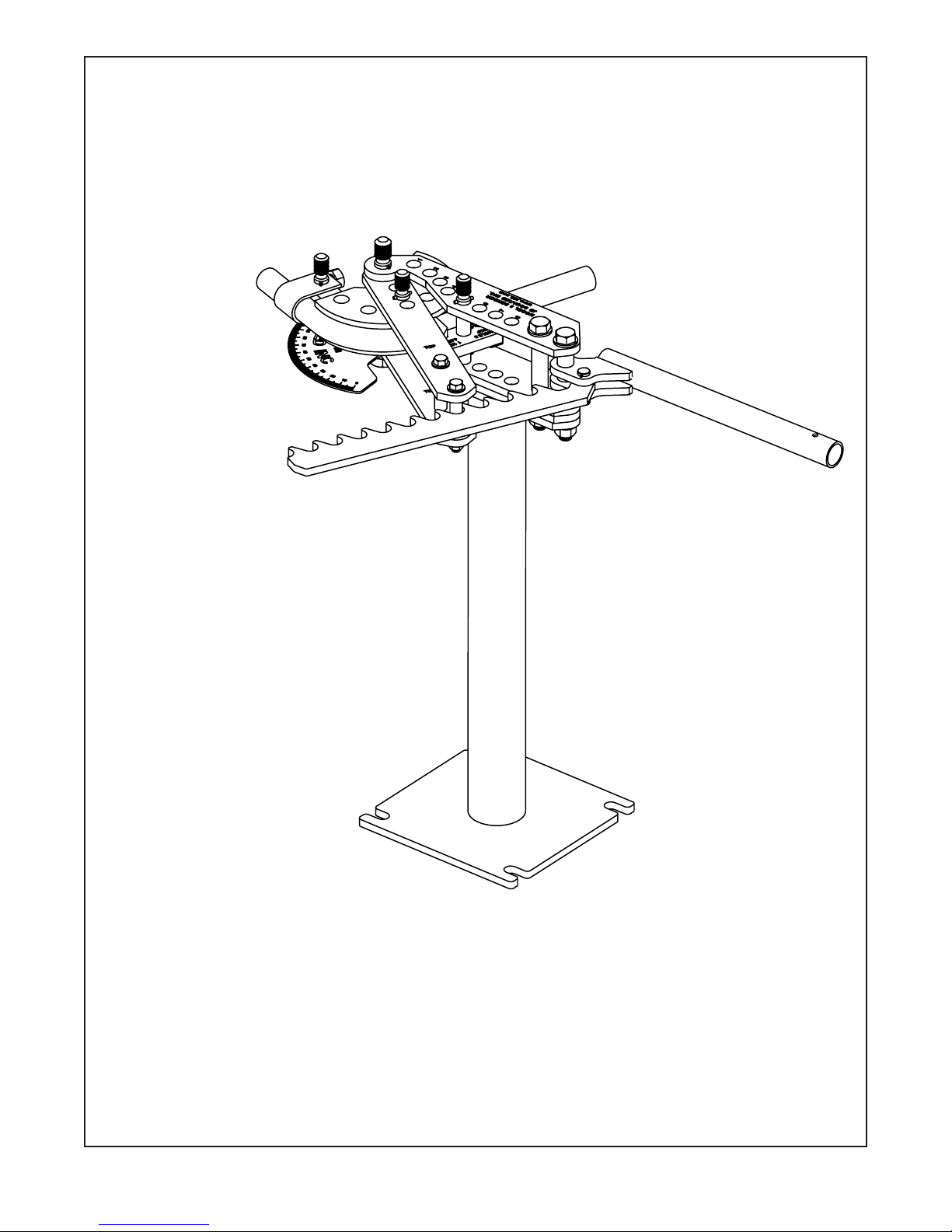
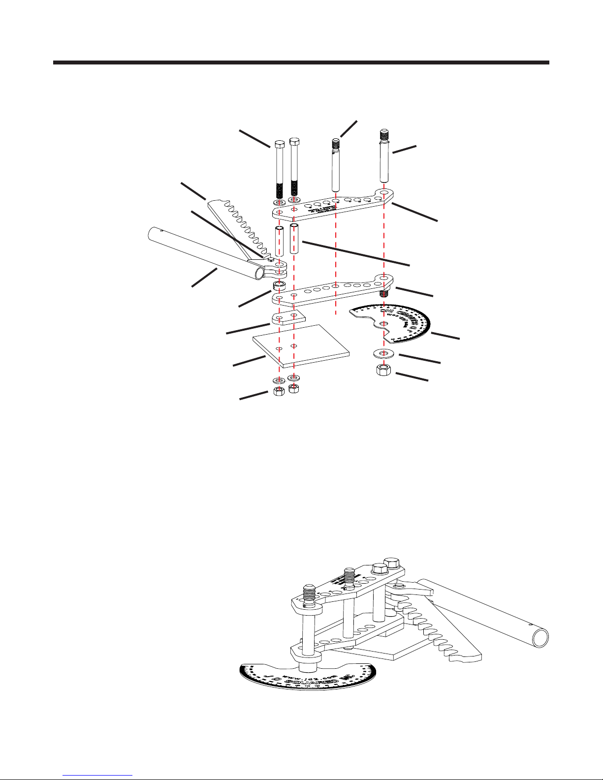
Die Set Installation and Bending Procedure
There are two types of forming dies provided for the Model 3 Bender. Those with drive holes and those without. The drive holes
aretheve1"holesdrilledinacircularpatternaroundtheformingdie'scenterhole.A7/8"diameterpininsertsthroughthedrive
links and through the forming die's drive holes when in operation. The drive holes are drilled 1/8" oversize to provide easier pin
installation.Toprepareforbending,followthestepsbelowdependingonthetypeofdieset.
WITH DRIVE HOLES:
Place the forming die into the bender using the 1"
framepin.Ifbendingsquaretubing,thoroughlylubricate
theformingdie'sgroove.However,ifbendingroundtubing
orpipe,NEVERlubricatetheformingdie'sgroove.Ifyou
do,thetubewilltendtoslipbackwardsinthediewhile
bending,whichinturncausesthetubingtokinkorwrinkle.
PlacethetubeintotheformingDie.InstalltheU-Strap
withtheshorter7/8"U-strappin.Ifnecessary,tightenthe
U-strapbolttopreventthetubefromslippingthroughthe
die will bending. It's a good idea to cut a slice out of a
bigger piece of tubing place it between the bolt and tubing
to prevent the bolt from dimpling the tubing. If bending
thinwalltubing(.065"orthinner)youmustalwaysuse
theU-strapbolt.
Next,usingthe7/8"FollowbarPin,placetheFollowbar
into the bender. See page 5 for the correct way to install
the Followbar. Lightly spray some lubricant on the outside
of the tubing so that the tubing will slide through the Followbar easily. Any spray lubricant works well. If you are bending tubing
withawallthicknessof.065"orthinneryoumaywanttoskipthelubeentirely.Thiswillhelpthefollowbarsticktothetubingduring
ratchet repositioning and generally helps prevent wrinkling. Make sure all pins are completely seated in their holes. Failure
to do this may cause damage to the bender links or worse yet the operator may slip and fall.
RotatetheRatchetLeverfullycounter-clockwise.EngagetheRatchetontotheouter3/4"drivelinkspacertube.Lightlypull
onthehandletopreloadthetubing.Donotpullhardenoughtoactuallybendthetubing.Usingafreehand,loosenthedegree
platenut.Rotatethedegreeplateuntilthedie'spointerisat0degreesandthenhandtightenthenuttosecureitintoposition.
Nowyou'rereadytobend.PullonthehandleinaclockwisedirectionuntiltheRatchetLevercannotrotateanyfurther.Returnthe
Ratchet Lever to the starting position. Initially release the Ratchet easily so as not to move the tubing and minimize spring back.
Reengagetheratchetandpullagain.WhenthelastRatchettoothisreached,returntheRatchetLevertoitsstartingposition.
Removethe7/8"DrivePinandrotatetheDriveLinkscounter-clockwiseuntiltheDrivePinmaybereinstalledthroughanother
holeintheBendingDie.Becarefulnottomovethetube.Nowrepeattheabovebendingsequenceuntilthedesireddegreeof
bendisobtained.Toreleasethetubingfromthebender,removethehandlefromtheRatchetLever.Insertitdiagonallythrough
the3/4"drivelinkspacertubesandpullcounter-clockwise.TheFollowbarwillreleaseitsgripandthetubingmayberemoved.
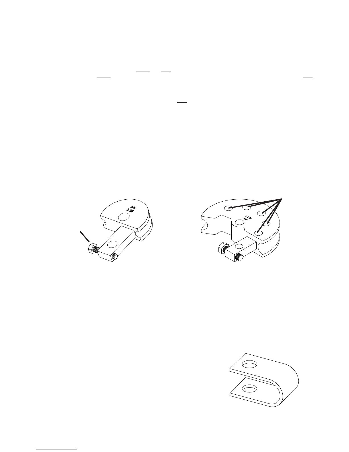
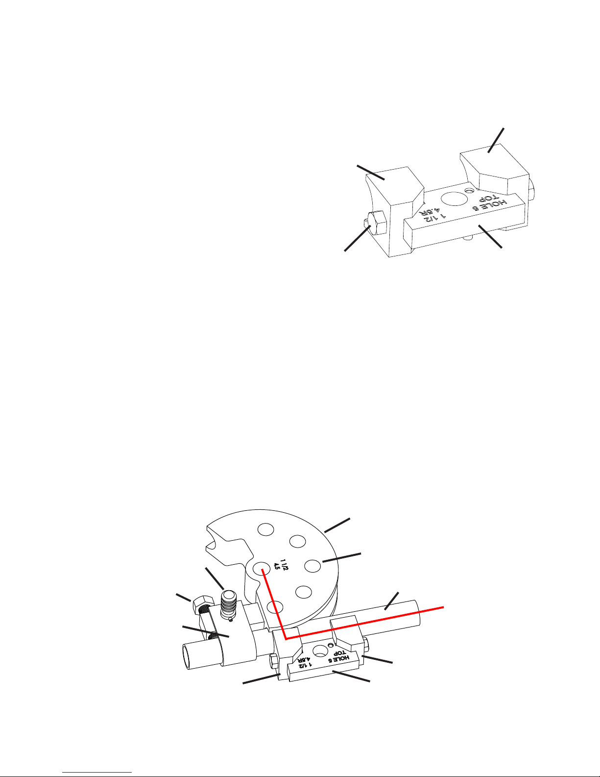
WITHOUT DRIVE HOLES:
These dies typically have a center line
radius of less than 3". Because the radius of
thedieissosmall,driveholescannotbedrilled
into the die. This does not present a problem
as the tube sizes for these dies is of relatively
small diameter and is easily bent. The ratchet
is not used.
Die installation procedure:
Swing the ratchet assembly out of the
way as shown below. Place the forming die
into the bender. Place the tubing to be bent
in the bender and using the 5 1/4" long drive
pin(nottheshorterU-Strappinthatisusually
used)installtheU-strap.Ifdesired,tightenthe
U-strapbolt tosecure thetubingto thedie.
This is not mandatory and may be omitted if
the tubing shows no signs of slipping through
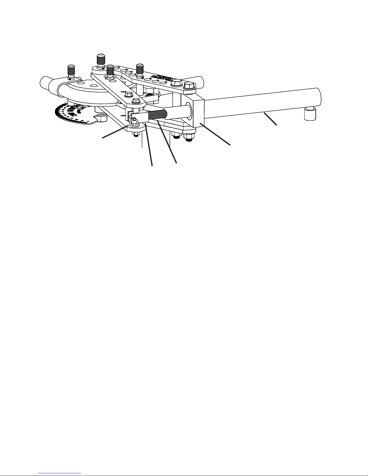
thediewhilebending.Nowinstallthefollowbarbeingsuretheword'TOP'isfacingup.Rotatethedrivelinksuntiltheirfrontedge
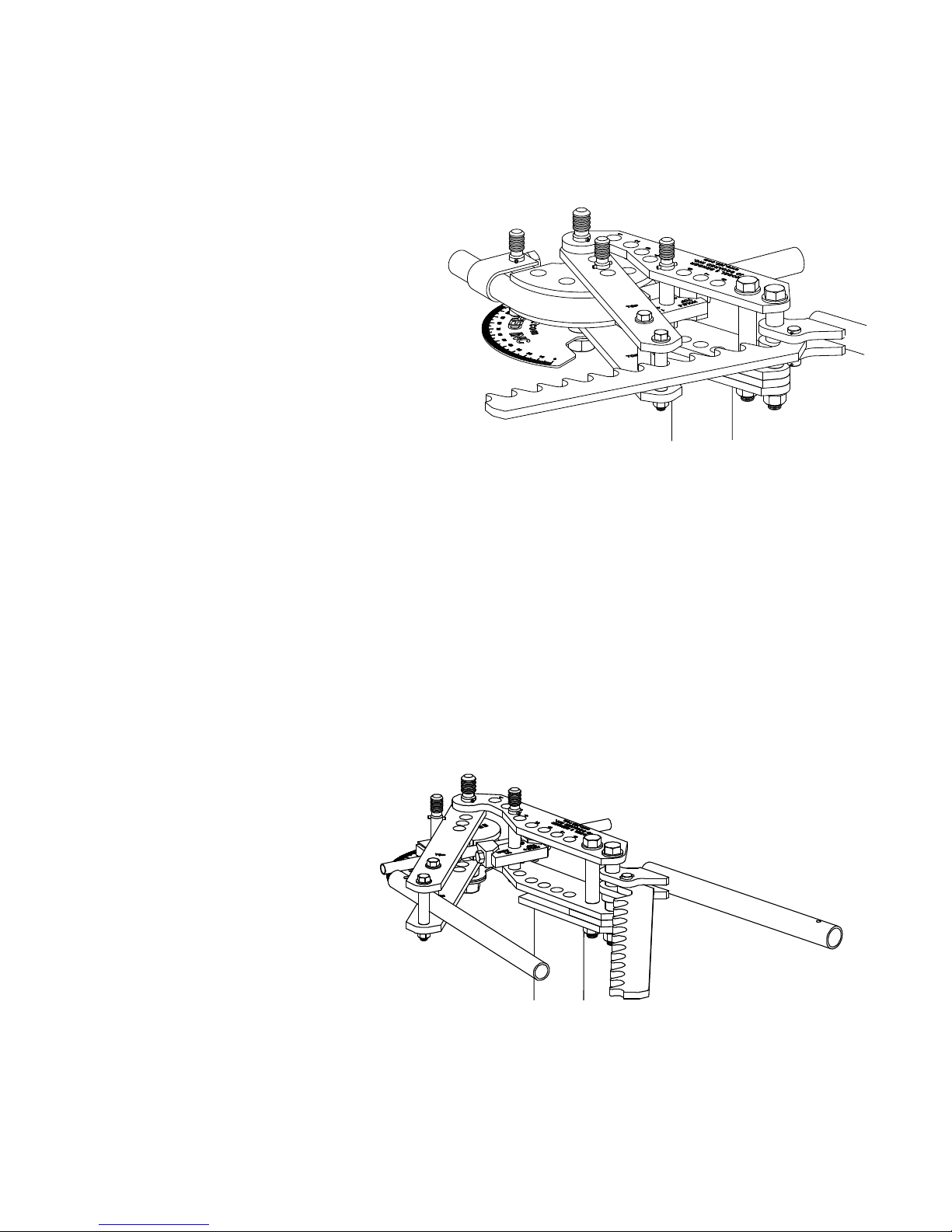
pushesdirectlyontheU-strappinasshowningure6.Placethehandlediagonallythroughthedrivelinks'two3/4"spacertubes.
Lightlypullonthehandletopreloadthetubing.Donotpullhardenoughtoactuallybendthetubing.Usingafreehand,loosen
thedegreeplatenut.Rotatethedegreeplateuntilthedie'spointerisat0degreesandthenhandtightenthenuttosecureitinto
position.Now,simplypullthehandleandobservethepointeruntilthedesireddegreeisreached.
- 7 -
Figure 14 - Handle installed and ready to bend without drive holes
Figure 13 - Bending with drive holes and ratchet

- 8 -
First,youneedtomakeatemplate.Forourexample,
wearegoingtouse11/2”o.d.x.120”wallweldedseam
mildsteeltubing.AsshowninFigure15,thetemplateisa
pieceoftubingbentto90degreeswithapproximately6”
of straight tubing on each side of the bend. Cut a piece of
tubingroughly30”long.Next,scribeanaccuratelineall
thewayaroundthistubing6”fromtheend.Anaccurate
and easy way to do this is to use an inexpensive pipe
cutter. Your local home supply store should carry them in
the plumbing department. A small lathe with a sharp cutter
alsodoesagoodjob.Scribethelinedeepenough,roughly
.015”,sothatwhenyoupaintthetemplate,thelineisstill
clearlyvisible.Handscribingthislineisdifcultandnotrec-
ommended. The tube should now resemble Figure 17.
Learning the operation of a bender is fairly easy. The real challenge is accurately placing the tubing
intothebendersothatthebendcomesoutintherightposition.Thisshorttutorialexplainsthesimple
process of template bending.
Make a sample bend called the Template as shown in Figure 15. A permanent mark scribed on the
template allows you to measure and visualize where the bend should be placed in the tubing. Once bent
the tubing will spring out to a larger radius than the forming
die’s size indicates. The larger the O.D. or the stronger
the tubing, the greater the springback. For instance,
chromemoly tubing will springback roughly twice as far
astheexactsamesizeandwallthicknessofweldedseam
mild steel tubing. By using a template bend with the same
kindoftubingyouaregoingtobend,youdonothaveto
worry about this springback because the template has
alreadysprungouttoitsnishedsize.
You may ask if buying bending software is a good
idea.Ibelievebendingsoftwarecanonlyjustiedfortwo
reasons:Creatingpartdrawingsifthesoftwaresupportsthat
functionandforsettingupafullyautomaticCNCbender
for the initial test of a part with multiple bends. Even using
the software the bend locations usually need to be hand
tweaked for accuracy before going into production. Most
professional fabricators use a method similar to what is
describedhere.Itisextremelyeasy,accurateandfast.
However,whatifyouneedtobend500pieces.Howwould
youusethisprocess?Don’tworry,it’sasimpletechnique
thatIwillexplainlaterbutrstlet’sjustcompleteasingle
piece job. To do this I’m going to go through the whole
process that I use to make a four bend rollbar for a racecar
asshowninFigure16.Thisisagreatexamplebecauseit’s
acommonrequest,therearenosimple90degreebends,
anditisgenerallyaone-offpiece.Soholdontoyourlug
nuts,herewego.
Bending Method #1 - Using Template Bends
The Easy Way To Position Bends
Figure 15 - Sample Template Bend
Let’s Make A Bend Template...
Figure 16
Sample Rollbar
Figure 17
Template Line

Load this tube into your bender as shown in
Figure18.Notethatonlythediesetandtubing
arevisibleinthegure.Theactualbenderand
thedieset’su-straparenotshownsothatyou
can see what we’re trying to achieve. Place the
scribedlineattheatedgeoftheformingdie.
Neverusethefollowbarasareference. Ifthe
formingdiehasalockboltonit,useittosecurely
tighten the tubing in place. It’s very important that
thismark stays in linewiththedie’satedge
during the bending process or template will not
give you accurate results later. Figure 18 - Tube positioned
in forming die
Template Line
Followbar
Forming Die
Figure 19
AsshowninFigure20,therollbarwillbe40”tallfromtheoortoitsUPPERside.Itwillbe62”wide
outsidetooutside.Thetoptwobendsare70oeachandthetwolowerbendsare20oeach. I recommend
that you purchase an adjustable carpenter's protractor to help determine the degree of bend for your
specicjob.Theyaremadeofclearplasticandhavelegsapproximately12”long.
To determine the total length of
tubing needed, you could sit down
and calculate it. This is described in
thenextsection"BendingMethod#2"
which presents a more mathematical
method to bend tubing. However, for
thisapplication,Ithinkit’sawasteof
time.Timeusuallycostmorethantubing,
sohere’sthefastway:Take thetotal
widthoftherollbar(62”)andadditto
twicetheheight(40”)whichgivesusa
lengthof142”(62”+40”+40”).Thisis
slightlytoolong,maybeafootareso,
butthere’sapopularruleinfabricating:
It is easier to remove material then to
addit.Throughexperienceyouwilllearn
howmuchextratubingyoumustleave
to complete the part.
Bendthetubetoanishedbendofexactly90degrees.Onthis
example,Ihadtobendto94degreestoachieveatrue90degree
bendafterthetubingrelaxed.Cutthestraightlengthoftubingthat
isnotscribedto6”longsothatitmatchesthescribedside.Thisis
not really necessary but it does look nice. Debur both ends and then
paintthetemplateaneasilyvisiblecolor.Whydoesitneedpaint?
It doesn’t. But after losing this thing a few times you’ll get the idea.
Thetemplateisnished.
If you work with different types of tubing that are of the same
sizebutdifferintheamountofspringbacktheyproduce,possibly
becauseofadifferentmaterialorwallthickness,youmayneedto
make a separate template for each one. You can decide later if this
necessary depending on the accuracy that you require.
Figure19showsanishedtemplatebendstillinthedie.Note
the position of the scribed line on the tube.
62"
40"
20°
70°
50"
Figure 20
Time To Start Bending...
- 9 -

Animportantruleofbendingisto,ifpossible,alwaysmakethebendsclosesttothecenterrstand
workyourwayout.Thisallowsyoutomakemeasurementcorrectionsbetweenbends.Basedonthisrule,
place a mark at the center of the rollbar tube. This is shown Figure 21.
BEND 1:
The rst bend will be the
upper right side bend. Referring
toFigure20,theupperdimension
of the rollbar is 50”. From the
center oftherollbartotheoutside
ofthebendis25”(50”dividedby
2). Lay the tubing to be bent on
theoorandholdthetemplate
with the scribed side parallel
totherollbartubinganddirectlyaboveit,asshowninFigure21.Thescribedsideofthetemplatewill
alwaysfacetowardsthecenterofthetubingbeingbent.Usingatapemeasure,slidethetemplateleftor
rightuntilitis25”fromitsoutsideedge,shownbytherightarrowinFigure21,totherollbar’scentermark.
Usingamarker,drawasmalllineontherollbardirectlybelowthescribedline.Takenoteofwhatside
of this mark the bend needs to be and draw an ‘X’ there so that when you load the tube into the bender
you’llbebendingonthecorrectside.Sincethedesiredbendisonly70oandthetemplateis90o,you
willhavetouseyourbestjudgementofwhenthetemplateis25”out.Thisgetseasierwithexperience.
Now,loadthetubeintothebenderandmaketherstbend.Don’tforgettooverbendalittletoaccount
fortubespringback.Forthismaterial3to4degreesshouldbesufcient.SinceallJDSquaredbenders
are equipped with degree of bend indicators this is easily accomplished. Once you know the correct over
bendrequired,youmaywanttorecorditforfuturereference.
BEND 2:
Place the template above
the rollbar tube with thetemplate
line facing bend 1 as shown in
gure22.Usingatapemeasure,
position it for the desired 50”
outside to outside of the two
top rollbar bends. DO NOT
use the tube’s center mark
as a reference and place the
template 25” left of center. The
reasonforthisisthatiftherst
bendwasnotmadeattheexactrightspottoachieve25”fromcenteryoucancorrectfortheerrorinthe
secondbend’sposition.Onceagain,sincethebendwillbe70oandthetemplateis90oyou must use your
judgementastowheretopositionthetemplate.Placeamarkontherollbartubeexactlyunderneaththe
template line. Load the tube in the bender so that the bend will be made on the CORRECT side of the
tubeandmakethe70obend.
Erasethecentermarkontherollbartube.Usingthetapemeasure,placeanewcentermarkexactly
midwaybetweentheoutsideofthetwobends.Why?Let’ssayyourmeasurementshowsthetwotop
bendsarereally501/4”wideinsteadofthedesired50”.Inthatcase,youroldcentermarkcouldbeoffby
asmuchasa1/4”.TheNEWcentermarkcorrectsthiserror.That’sthecoolpartabouttemplatebending.
Yourerrorscangenerallybexedwiththenextbend.Alsonotethatifyouhadnotstartedyourbending
from the center of the rollbar you would not have been able to make the correction. Every bend adds a
littlemoreerrorandyouendupwitharollbarthatdoesnott.
25”
50”
Figure 21 - Template positioned for 1st bend.
Figure 22 - 2nd bend position
Tube’s
Center Mark
Template Line
Template Line
- 10 -

31”
62”
Figure 23 - 3rd bend position
Figure 24 - 4th bend position
BEND 3:
At this step you may want to use
alarge90osquare to help position the
template. Position the template above
the rollbar tube with the template line
facing up towards the top of the rollbar
asshowningure23.Slidethetemplate
up or down the rollbar tube until its
outside is 31” from the rollbar’s center.
Mark your tube and make the bend.
BEND 4:
Position the template with the
template line facing up towards the
top of the rollbar as shown in gure
24. Slide the template up or down the
rollbartubeuntilitsoutsideis62”from
theoutsideofthe3rdbend.Also,verify
the bend is the same distance down
the tube from the top of the rollbar. If
all is correct mark the tube and make
the bend.
Lastly, cut the ends of the tube
tomaketherollbar40”talland your
done.
Finished!
PROCEDURE FOR SETTING UP A PRODUCTION BENDER USING THE TEMPLATE METHOD
AsIstatedearlier,thismethodcanbeusedforproductionbending.Theideaofmakingthebends
from the center out doesn’t usually work well in production. Most production bending is done by feeding
thetubethroughthebenderandmakingeachbendasneeded,therebyeliminatingtheneedtoremove
thetubefromthebenderandipitaround.Forthisyouwouldwantasetupsheetwiththelocationsof
where to place the marks on the tubing for each bend location. The problem with template bending is that
the template has the tube stretch and springback already in it. Since the tubing will grow in length as you
makebendsinit,howcanyoumeasureitaccuratelyonceit’sbent?Unfortunately,youcan’t.Whatyou
mustdoisplacemarksdownthetube,forexample10”apart,startingattheoneendbeforeyoustart
bending.Nowwheneveryoutransferthemarkfromthetemplatetothetubebeingbentyoucaneasily
measurethedistancefromoneofthe10”markstodeterminewherethemarkwouldofbeenplacedon
an unbent piece of tube.
- 11 -

TherstthingyouneedtodoistodeterminetheactualstartinglocationofabendproducedbytheBendingDieyouinstalled
inthebender.Thiscanvarybetweendiesetsandmustbecheckedforeverydiesetpurchased.Inthebelowexampleweare
using11/2"O.D.tubingandaBendingDiewithaCenterLineRadiusof61/2".
Here'stheprocedure:
A) Placeapieceoftubing(app.21/2'long)intothebendersothatexactly12"extendsoutfromtheedgeofthedietothe
end of the tubing when the tubing is fully seated in the Bending Die's groove. Place a little bending pressure on the tube
soastoseatthetubingintheBendingDie.Notenoughtostartbendingthetubingjustenoughtoseatitinthegroove.
NOTE: If you lay a small length of tubing in the groove of a Bending Die you will notice the tubing does not seat to the
bottom of the groove. The Bending Dies are deliberately machined this way so that during the bending operation a
side force is developed in the tubing. This helps to reduce at spotting and
wrinkles.
B) Using a Black Magic Marker mark a line on the
tubingpreciselyattheedgeofthedie.Seegure
25.
C) Bend the tube to an exact 90 degrees. Use a
carpenters square to check the angle. You will
have to overbend the tube a little to account for
springback.Howmuchtooverbendwillcomewith
practice. If you overbend the tube a little don't worry.
Becausecoldworkedsteelhasmemory,youcan
place the tube in a vise or anything else that will
retainit,andsimplyunbendit.Obviouslythisonly
works for small amounts of overbend. If the tubing
isunderbent,itwillbenecessarytoputitbackinto
the bender.
D) Withthetubebentcorrectlyto90degreeslocate
theactualstartofthebend.Todothis,measure
fromtheendofthetubetothefarendofthe90
degreebend.Intheexampleingure26thiscame
outat20 1/4".Subtract61/2"forthecenterline
radius(CLR)oftheBendingDie,another3/4"for
theradiusofthetubingnotseatedinthedie,and1/8"forspringback.(SubstitutetheCLRandtuberadiustomatchyour
dieset).The1/8"gureforspringbackisanapproximation,notanexactgure.Howeveritisusuallyveryclosetothe
realthingandmaybeusedwithoutworrytodeterminetheactualstartinglocationofthebend.So:
20 1/4" - 6 1/2" - 3/4" - 1/8" = 12 7/8"
Nowsubtractfromthe127/8"theoriginal12"wehad
markedearlierandyoundthatthebendwillactually
start7/8"infromtheedgeofthebendingdie.Nowwe
knowforexample,ifwewant40"fromtheendofthe
tubingtothestartofthebend,wemustsubtract7/8"
from40"andsetthetubing391/8"fromtheedgeof
the Bending Die.
Anotherexample,youwant36"fromthebottomtothe
top of a rollbar. Tube size is 1 3/4" and you have an
actual bend start 1/2" inside of the Bending Die's edge.
TheCLRoftheBendingDieis71/2".So:36"-1/2"
(ActualBendstart)-71/2"(CLRofdie)-7/8"(Half
ofthetubingdiameter)-1/8"(Springback)=27".Set
the tube 27" from the edge of the Bending Die and
make the bend.
Bending Method #2 - Using Math Formulas
Figure 25
Actual start
of bend
6 1/2" CLR
7/8"
20 1/4"
12"
Mark
Figure 26
Mark here at the saw cut edge of
die (not at the followbar's insert)
- 12 -

- 13 -
Example hoop :
Preparation is the key to making accurate bends. To make multiple bends in one section of tubing you will need a universal
protractor.Theprotractoristhenclamped,usingamachinistv-blockandaradiatorhoseclamp,tothetube.Makesurethepointer
indicates'0'beforemakingyourrstbend.Alsousingacarpenter'slevel,makesurethetubeisenteringthebenderlevel.On
thesecondbendifyouturnthetubesothatthepointeragainreads'0'andthecarpenter'slevelindicatesthetubeislevel,both
bends will be on the same plane with no noticeable twist.
First step is to draw a sketch of the intended shape and all measurements. Figure 27 below is the desired hoop. The Bending
Diehasacenterlineradius(CLR)of61/2".ThetubeO.D.is11/2".Wedeterminedearlier,usingthemethoddescribedonpage
4,thattheBendStartmeasurementis3/4"behindtheedgeofthisparticularBendingDieset.
1) Determine the total length of tubing needed. Using a calculator and the formula below let's add it all up.
6 1/2" (CLR of bend) x 90 (Number of degrees of bend) x .0175 = Length of tubing used in a bend.
Usingtheformulaaboveweget61/2"(CLRofbend)x90(Degreesofbend)x.0175=10.2375.Let'sroundthisoffto101/4"
inches(10.250").Thisistheamountoftubingusedinthebend.Wehavetwobendssowedoublethisandget201/2".Addto
thisthestraightsectionsandweget201/2"(tubinginbends)+27(thecentersection)+131/2"fortheleftupright+131/2"for
therightupright=741/2"oftubingneeded.It'susuallyagoodideatoleaveacoupleofinchesextraontheend.Remember,
it's easier to remove tubing then to add it. So let's add 2" to 74 1/2".
2)Wecutourtubeto761/2".It'sgenerallyeasiertoworkfromthecenteroutwhenmakingtwobendsinatube.Divide741/2"
by 2 and our center point is 37 1/4" from the end of the tube. Place a mark on the tubing 37 1/4" in from one edge and mark the
tubingsoyouwillknowwhichsideisthe371/4sideandwhichsideis391/4".Noticewedidn'tusethe761/2"measurement
thatwecutourtubingto.Thiswayweonlyhavetocut2"offoneendofthenishedtubeinsteadof1"offeachend.Therst
bend is made on the short 37 1/4" side.
3)Usingthemethoddescribedonpage4wedeterminethatthetubeshouldextend125/8"fromtheedgeoftheBendingDie.
Below is the equation from page 4.
20" (Height of hoop) - 6 1/2" (CLR of die) - 3/4" (1/2 of tube's dia.) - 1/8" (Springback) - 3/4" (Bend Start) = 11 7/8".
Aftermakingthebendwehavehalfourhoopcompleted.Thetopofthebendis20"fromthebottomofthetube.
4)Nowfortheotherbend.Firstweneedtodeterminehowmuchthetubestretchedinthebendarea.Fromgure9weseethat
thetubeshouldbe203/4"fromtheoutsideedgetoour371/4"centermark.Howeveraftermeasuringfromourcentermarkto
theoutsideedgeofthebendwenowhave21"andnottheplanned203/4".This1/4"increaseisduetospringbackandthetube
stretching in the area of the bend.
Figure 27- Example hoop.
6 1/2" CLR
3/4"
20"
20 3/4"
20"
40"
13 1/2" 13 1/2"
1 1/2"
Start of 2nd bend
Center mark on tube
End of 1st bend
Start of 1st bend
C
L

- 14 -
Ifwenowrepeatedthesecondbend,usingthesame125/8"fromtheendofthetubing+2"fortheextratubingweallowed,
wewouldendupwithahoop1/2"toowide.Thisisbecausethe1/4"stretchdevelopedintherstbendwillalsobedevelopedin
thesecondbend,givingus1/2"totalincreaseinwidth.Notagooddealifyouonlywanta40"widehoop.Sowhat'sthesolution.
Actually there is two ways to do it.
FIRSTMETHOD:
Lookatgure27andnoticethesecondbendstartsatthetopofthehoopandnotatthetopoftheuprightastherstbenddid.
Also the start of the second bend is drawn as 13 1/2" from the center mark. If you take the 13 1/2" measurement and subtract
the1/4"ofgrowththatwasdevelopedintherstbendandanother1/4"tocompensateforthesecondbend'sgrowthyouendup
with13".Subtractanother3/4"toaccountforthe3/4"BendStartlocationontheBendingDiesetandwehaveanalsettingof12
1/4".Noticewedidnotsubtractan1/8"forspringback.Thisisaccountedforalreadyinthe1/4"weaddedforthesecondbend's
growth.SetthetubesothattheBendingDiesedgeisexactly121/4"fromthecentermark.Makesuretheuniversalprotractor
reads'0'andthecarpenter'sleveliscentered.Asonenalcheckyoucanalsomeasurefromthefarsideofthecompletedbend
totheedgeofthebendingdie.Seegure28.Thismeasurementshouldread:
40" (width of hoop) - 3/4" (radius of tube not in bending die) - 1/8" (springback allowance) = 39 1/8"
Makethesecondbend.Measuretheheightoftheseconduprightandcutofftheextratubingweallowedforearlier.
SECONDMETHOD:
Thesecondmethodisbasicallytheoppositeoftherstmethod.ThesecondbendwillstartatthebottomoftheuprightandNOT
atthetopofthehoopasintherstmethodandasshowningure28.Weusethesamemethodasusedtobendtherstbend
withafewexceptions.Firstcalculatethestartingpointforthesecondbendasshownbelow:
20" (total height of hoop) - 6 1/2" (CLR of bending die) - 3/4" (Bend Start) = 12 3/4"
Add2"toaccountfortheextratubingweallowedearlier.Alsoaddthe1/4"growthdevelopedintherstbendandanother1/4"for
thesecondbend.DONOTADD1/8"SPRINGBACK.Onceagainthisisalreadyaccountedforinthe1/4"growthofthesecond
bend.Weendupwith:
12 3/4" + 2" (extra tubing) + 1/2" (growth for both bends) = 15 1/4"
Setthetube'sendat151/4"fromtheBendingDie'sedge.Makesuretheuniversalprotractorreads'0'andthecarpenter'slevelis
centered.Makethesecondbend.Measuretheheightoftheseconduprightandcutofftheextratubingweallowedforearlier.
Thank you for purchasing a JD Squared bender. Any further questions please contact us.
21"
39 1/8"
Start of 2nd bend
Center mark on tube
Start of 1st bend
C
L
Figure 28
Table of contents
Other J D Squared Construction Equipment manuals