Labounty MHP 350 Operating instructions

Part Number 514990
4/2019 Ver. 7
CE Operating and
Maintenance Manual
MHP SERIES
MOBILE HYDRAULIC PULVERIZER

2 MHP Operating & Maintenance Manual MHP Operating & Maintenance Manual 3
IMPORTANT
This operator’s manual must accompany the attachment at all times and be readily available to the operator.
MANUAL REPLACEMENT
Should this manual become damaged, lost or additional copies are required, immediately contact any
authorized LaBounty dealer. You may also download a PDF copy at www.stanleyinfrastructure.com.
REGISTRATION FORM
The Warranty Registration Form must be lled out by the dealer or customer and returned to LaBounty
indicating the date the machine went into service.
POSSIBLE VARIATIONS
LaBounty cannot anticipate every possible circumstance that might involve a potential hazard, as the owner’s
requirements and equipment may vary. Therefore, the warnings in this publication and on the product may not
be all-inclusive and you must ensure that the procedure, application, work method and operating technique is
safe for you, and others, before operation.
PUBLIC NOTICE
LaBounty reserves the right to make changes and improvements to its products and technical literature, at any
time, without public notice or obligation. LaBounty also reserves the right to discontinue manufacturing any
product at its discretion, at any time.
WARRANTY
All work or repairs to be considered for warranty reimbursement must be authorized by the LaBounty Service
Department before work is started. Any alterations, modications or repairs performed before authorization by
the LaBounty Service Department will render all warranty reimbursement consideration null and void without
exception. Improper operation or improperly performed maintenance may render any warranty null and void.
This manual contains information for the safe and proper operation and maintenance of the LaBounty MHP
Mobile Hydraulic Pulverizer. Read the entire manual before the initial start-up of the attachment. It is important
to know the correct operating procedures of the attachment and all safety precautions to prevent the possibility
of property damage and personal injury.
The LaBounty attachment has been designed and manufactured with high quality materials and care in
workmanship. The instructions in this manual have been prepared to ensure that, when followed properly, the
attachment will provide efcient and reliable service. Continuing product development and improvement may
have caused changes in the attachment that are not reected in this manual. If a question arises regarding
the operation or maintenance of the attachment, contact a LaBounty dealer for the most current information
available.
PREFACE

2 MHP Operating & Maintenance Manual MHP Operating & Maintenance Manual 3
TABLE OF CONTENTS
Safety................................................................................. 4
Operational Safety ........................................................................5
Decals & Terms .............................................................................7
Installation......................................................................... 8
Third Member Installation..............................................................8
Hydraulic Installation.....................................................................9
Operation........................................................................... 10
Technical Specications................................................................11
Attachment Controls......................................................................11
Bleed the Hydraulic Cylinder.........................................................12
Operating Tips...............................................................................12
Maintenance...................................................................... 13
Swift-Lock Teeth Maintenance ......................................................15
Lubrication.....................................................................................16
Inspect / Torque Bolts....................................................................17
Check for End Play .......................................................................17
Blade Maintenance .......................................................................18
Build Up & Wear Plates.................................................................19
Checking and Replacing Wear Plates...........................................19
Hydraulic Maintenance..................................................................21
MHP Hydraulic Schematic ............................................................21
Inspect the Thrust Washer ............................................................22
Troubleshooting ............................................................... 25

4 MHP Operating & Maintenance Manual
Always observe safety symbols. They are included for your safety and for the protection of the tool.
Your safety and the safety of others is a direct result of how you operate and maintain your
equipment. Read and understand this manual and other safety information provided with the
base machine and be sure that you understand all controls and operating instructions before
attempting to operate this equipment. Failure to follow the safety precautions can result in
personal injury, death or property damage.
Carefully read all safety messages in this manual and on your equipment safety decals. Keep
safety decals in good condition. Replace missing or damaged safety decals.
Because LaBounty cannot foresee all hazardous circumstances, the precautions listed in
this manual and on the equipment are not all-inclusive. If a procedure, method, tool or part is
not specically recommended by LaBounty, determine whether it is safe for you and others,
and that the equipment will not be damaged or made unsafe as a result of your decision to
implement it.
The basic rules are summarized in this section of the manual. They also appear throughout
the manual along with additional specic rules for safety and operation.
This is the safety alert symbol. It is used to alert you to potential
personal injury hazards. Obey all safety messages that follow this
symbol to avoid possible injury or death.
This safety alert and signal word indicates an imminently
hazardous situation which, if not avoided, will result in death or
serious injury.
This safety alert and signal word indicates a potentially hazardous
situation which, if not avoided, could result in death or serious
injury.
This safety alert and signal word indicates a potentially hazardous
situation which, if not avoided, could result in minor or moderate
injury.
This signal word indicates a situation which, if not avoided, will
result in damage to the equipment.
SAFETY

MHP Operating & Maintenance Manual 5
• If the attachment is not functioning properly, shut
down the machine, follow proper lockout / tag out
procedures and follow proper repair procedures.
• NEVER operate equipment without the original
safety guards in place.
• Ensure that the cab is equipped with the proper
safety guards for LaBounty applications. The
cab MUST be equipped with an approved Falling
Object Protection Structure (FOPS). The FOPS
must meet the requirements of SAE standard
J1356. A transparent, shatter-resistant shield
covering the front of the cab, is also required.
Contact your base machine equipment dealer
or manufacturer for more information on the
availability of FOPS. Lack of proper FOPS may
result in injury or death.
• NEVER operate the excavator without a proper
restraint (seat belt) system in place. Doing so can
create loss of control or ejection from cab.
• NEVER operate the equipment while under the
inuence of drugs, alcohol or other substances
that inhibit mental abilities or reaction time.
• DO NOT process material with the attachment
over the operator’s cab. Doing so will result in
severe personal injury or death from falling debris.
• DO NOT attempt to process brittle materials, such
as axles and railroad rail. DO NOT process any
material in a position that may propel it toward the
operator, other workers, buildings or equipment.
• Clear all persons and equipment from the area of
operation and machine movement. NEVER move
loads over people or equipment. When viewing
the operation of the attachment, maintain a safe
distance of at least 75 feet (23 meters).
• NEVER approach power lines with any part of the
machine. Keep clear at a minimum of 15 feet (5
meters).
• DO NOT close the attachment on a structure and
reverse the excavator in an attempt to pull down
material.
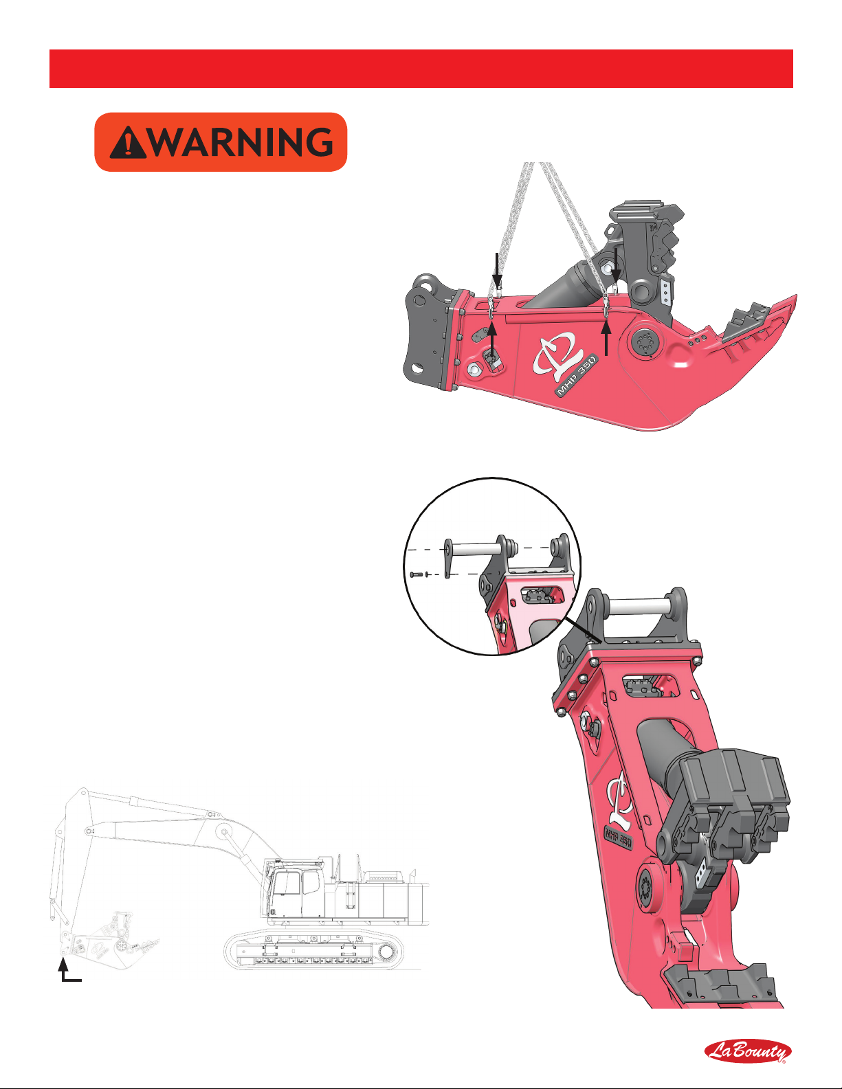
• Avoid tipping. The attachment will alter the
lift capacities of the base machine. DO NOT
overload the excavator or serious injury could
result. Lift capacities will vary if the base machine
is not on level ground. Lifting incorrectly can
cause severe injury or machine damage. Use
the recommended excavator counterweight.
Use short slings and lift the load only as high as
necessary.
• Use of this tool on certain materials could
generate dust potentially containing a variety
of hazardous substances, such as, asbestos,
silica or lead. Inhalation of dust containing
these, or other hazardous substances could
result in serious injury, cancer or death. Protect
yourself and those around you. Research and
understand the materials you are processing.
Follow safety procedures and comply with all
applicable national, state or provisional health and
safety regulations relating to them. If appropriate,
arrange for the safe disposal of the materials by a
qualied person.
• Disassembly of any pin-connected attachment
can be hazardous. NEVER remove any pin unless
the attachment is on the ground and blocked
up. Serious injury or death could result. Metal
chips or debris may y when a connecting pin is
struck. Use a brass drift when striking pins and
always wear protective clothing and proper eye
protection. Pins may y when struck with force
to drive them in or out. Always keep people clear
when removing or installing pins.
• DO NOT allow riders on the machine. Riders are
subject to serious injuries, such as being struck
by foreign objects or being thrown off the machine.
Riders also distract and obstruct the operator,
resulting in the machine being operated in an
OPERATIONAL SAFETY

6 MHP Operating & Maintenance Manual
OPERATIONAL SAFETY
unsafe manner. NEVER use the attachment as a
work platform or personnel carrier.
• DO NOT modify LaBounty equipment without
factory authorization. This equipment is designed
to do a specic job and alterations could result in
injury.
• ALWAYS lower the boom to the ground before
leaving the cab. If it is necessary to work on an
attachment off the ground, securely support the
machine and attachment. DO NOT support the
machine on cinder blocks, hollow tiles or props
that may crumble under continuous load. DO NOT
rely on a cylinder to hold the attachment in the
air. If a control is moved or hydraulic pressure is
otherwise released, the attachment may drop. DO
NOT work under a machine that is supported only
by a jack.
• Hydraulic oil becomes hot during operation. DO
NOT come in contact with hot hydraulic oil as
it could cause severe burns. Wear adequate
protective clothing and safety equipment.
• DO NOT tamper with hydraulic lines or
components while they are pressurized. Escaping
uid under pressure can penetrate the skin,
causing serious injury. Keep hands and body
away from pinholes and nozzles which eject uids
under high pressure. Use a piece of cardboard to
search for leaks. If ANY uid is injected into the
skin, seek immediate medical assistance.
• DO NOT weld on any structural member unless
specically authorized by LaBounty.
• ALWAYS wear close-tting clothing and safety
equipment appropriate to the job. Safety
equipment should be worn at all times when
viewing, operating or maintaining the attachment.
Safety equipment includes eye protection, hard
hat, steel toe shoes, gloves, hearing protection
and respirator.
• Keep clear of potential pinch points, including the
moving upper jaw, cylinder connections, bucket
linkages and other moving parts.

MHP Operating & Maintenance Manual 7
Top and front cab
guarding required during
any material processing
application
CAB GUARD DECAL
P/N 503647
Figure 7
DECALS & TERMS
MODEL DESCRIPTION
MHP series Mobile Hydraulic Pulverizers are designed for quiet, controlled demolition and recycling of concrete
structures. MHP uses crushing teeth to efciently separate rebar from concrete.
DECAL MAINTENANCE
Ensure safety decals are installed and visible. Keep decals clean and promptly replace decals that are
damaged. Replacement decals are available through the LaBounty Service Department. Place replacement
decals in the same position as the original decals.
UPPER JAW
ARM CONNECTION
LINK
CONNECTION
SWIFT-LOCK
TEETH
REBAR
BLADE
LOWER TOOTH
PLATEN
FRONT
CYLINDER
PIN
REAR
CYLINDER
PIN
MAIN PIVOT GROUP
SAFETY FIRST DECAL
P/N 503590
(INCLUDED WITH MANUALS)
Figure 5
GREASE DECAL (AT EACH FITTING)
P/N 116388
Figure 6
Keep 75 feet (23m)
away when operating
SAFE DISTANCE DECAL
P/N 503706
Figure 4
1538 Highway 2
Two Harbors, MN 55616
tel: 1-800-522-5059
fax: 218-834-3879
www.stanleyhydraulics.com
Made in the U.S.A. with Global Materials
Attachment Model:
Serial Number:
Year of Manufacture:
Weight:
MODEL/SERIAL NUMBER PLATE
P/N 511045
Figure 3
U.S. PATENT NUMBERS EPO PATENT NUMBERS
5,474,242 7,240,869 435,702
5,531,007 7,487,930 737,107
5,992,023 7,578,461 1,682,299
7,322,273 7,832,130 1,789,225
8,146,256 8,104,384
STANLEY LABOUNTY
1538 Highway 2 1-800-522-5059
Two Harbors, MN 55616 www.stanleyhydraulic.com
FOREIGN PATENTS AND OTHER PATENTS PENDING
116404
PATENT PLATE
P/N 116404
Figure 2
CYLINDER BLEED DECAL
P/N 512554
Figure 8
PRESSURE RELIEF
WARNING DECAL
P/N 512572
Figure 1

8 MHP Operating & Maintenance Manual
INSTALLATION
• Use only approved rigging hardware rated
for loads greater than the weight of MHP.
• Hooking Points are for moving the
attachment only. Do not lift other objects or
use MHP in a cable-hung application.
HOOKING POINTS FOR LIFTING
Figure 9
LINKAGE CONNECTION
REMOVE ARM & LINK PINS
Figure 10
1. Locate at, hard ground (e.g., concrete oor)
for installation. Lift and place the attachment
on the ground as shown. Use blocking if
necessary.
2. Remove the excavator bucket. Follow the
manufacturer’s recommended procedure.
Note: When removing the excavator bucket, plug
hydraulic hoses to prevent contamination.
THIRD MEMBER INSTALLATION
3. Remove the arm connection and link
connection pins, as shown in Figure 10.
4. Bring the excavator into position, carefully
lining up the stick tip with the MHP mounting
bracket. Pin the stick tip to the MHP mounting
bracket using the pin provided (see Figure 11).
5. Carefully extend the bucket cylinder to move
the bucket linkage. Position the link into the
mounting bracket linkage connection.
Note: It may be necessary to use a lifting device
(overhead hoist, forklift, etc.) to position the link.
6. Pin the linkage connection to the MHP bracket..
THIRD MEMBER INSTALLATION
Figure 11

MHP Operating & Maintenance Manual 9
INSTALLATION
HYDRAULIC INSTALLATION
Note: Refer to “MHP Hydraulic Schematic” on page 21.
• DO NOT install hydraulic lines while they are pressurized.
Escaping uid under pressure can penetrate the skin,
causing serious injury.
Hydraulic Circuit Requirements
Model Cylinder Circuit Connection
MHP 200 40-65 GPM (150-250 LPM)
4500-5500 PSI (310-380 Bar) 1” Code 62 Flange
MHP 350 50-110 GPM (190-416 LPM)
4500-5500 PSI (310-380 Bar) 1” Code 62 Flange
1. Connect hydraulic hoses from the base machine to the connections on MHP (Figure 12).
Note: Remember to cap all hydraulic hoses and ttings immediately to prevent contamination of the oil.
2. Check for any hydraulic oil leaks or interference.
Note: Hydraulics will need to be bled before putting into service (see “Bleed the Hydraulic Cylinder” on page 12).
CYLINDER CIRCUIT
(1 ON EACH SIDE)
HYDRAULIC CONNECTIONS
Figure 12

10 MHP Operating & Maintenance Manual
OPERATION
BEFORE YOU START
Know Your Safety Program
• Read and understand this manual and the base
machine manual.
• Know the employer’s safety rules. Consult your
foreman for instructions and safety equipment.
• Learn the trafc rules at the work site. Know
the hand signals used on the job and who is
responsible for signaling. Take signals from only
ONE person.
• Wear personal protection equipment. This
includes eye protection, hard hat, steel toe shoes,
gloves, hearing protection and respirator.
Know Your Equipment
• Learn and test the function of all controls. If
malfunctions are found, shut the machine down
and report the malfunction for repair.
• Be familiar with safety devices, indicators, warning
devices and caution instructions. They will alert
you to conditions that are hazardous.
• Know the clearances in the work area.
Daily Safety Checks
• Ensure all decals are installed and legible.
Contact LaBounty for replacements as required.
• Have a DAILY safety dialog with all workers.
Inform them of any abnormal work that is planned.
Remind them of the safe working distance.
• Clear the area. ALWAYS look out for others.
In any work area, people constitute a serious
safety hazard. Before operating, walk around the
machine to ensure no workers are next to, under
or on it. Warn nearby workers that you are starting
up. DO NOT start up until they are out of danger.
• Check the location of cables, gas lines and water
mains before operation. Ensure work site footing
has sufcient strength to support the machine.
When working close to an excavation, position
machine with the propel motors at the rear.
• Keep bystanders clear, especially before moving
the boom, swinging the upper structure, or
traveling. ALWAYS be alert for bystanders in or
near the operating area.
Safety Devices
• Seat belts • Canopies
• Safety decals • Shields and guards
• Flags and ares • Barricades
• Signs and other
markings
• Warning lights
• Falling Objects
Protective Structures
(FOPS)
• Visual or audible
warning devices
General Rules For Safe Operation
• KNOW the capacity of the excavator and it’s
attachments. DO NOT overload or serious injury
could result. The attachment may have altered
the machine’s lift capabilities.
• MHP is for processing materials. DO NOT use for
unapproved purposes or warranty may be voided.
• If MHP stalls during processing, scale back the
amount of material being processed at one time.
Overloading can cause overheating and has
adverse effects on the hydraulic system.
• Cycle the MHP cylinder completely when
processing. Fully cycling MHP will allow hydraulic
uid to circulate and prevents overheating.
• Maintain a safe distance.
• NEVER leave MHP suspended or pass it over
people, occupied vehicles or buildings.
• When working in conned spaces, keep watch on
exposed parts, such as cylinder rods and hoses,
to avoid damage.
• Maintain at least 15 feet (5 meters) between MHP
and any nearby power lines.
• ALWAYS lower MHP to the ground and turn the
base machine off when leaving the machine
unattended.
• DO NOT close the jaws on a structure and
reverse the excavator in an attempt to pull down
material. This is dangerous and will damage the
excavator and the MHP attachment.
• DO NOT alter factory preset hydraulics. This may
void the warranty.
• DO NOT shear high tensile steel, such as railroad
rail, spring steel, axles and some types of wire.
Jaw damage will result. This type of material
breaks when processed and can become a
projectile which could cause injury or death.

MHP Operating & Maintenance Manual 11
OPERATION
ATTACHMENT CONTROLS
BUCKET DUMP → ATTACHMENT OUT
Figure 13
BUCKET CURL → ATTACHMENT IN
Figure 14
• Learn the control for each movement of the
attachment before attempting to operate.
AUXILIARY SWITCH → JAWS CLOSE / OPEN
Figure 15
TECHNICAL SPECIFICATIONS
Model Weight Jaw
Opening
Jaw
Depth
Lower
Width Reach Max.
Pressure Max. Flow
Cycle
Time
(@ Max.
Flow)
Minimum
Excavator
Size
MHP 200 4850 Lbs.
(2200 Kg)
37 in
(940 mm)
33 in
(840 mm)
21 in
(530 mm)
8.9 ft
(2.7 m)
5500 PSI
(380 Bar)
65 GPM
(245 LPM) 4 sec. 44000 Lbs
(20 M/Ton)
MHP 350 6650 Lbs.
(3000 Kg)
44 in
(1120 mm)
40 in
(1020 mm)
24 in
(610 mm)
9.5 ft
(2.9 m)
5500 PSI
(380 Bar)
110 GPM
(415 LPM) 4 sec. 66000 Lbs
(30 M/Ton)

12 MHP Operating & Maintenance Manual
OPERATION
Air must be bled out of the cylinder prior to operation.
Air in the system leads to cavitation, oxidation of the
oil and excessive heat. These conditions promote
hydraulic oil break-down, contamination, noise,
sluggish operation, reduced component life and
potential cylinder damage.
1. Start with the attachment cylinder fully retracted.
Shut off the excavator and operate the jaw
controls in order to relieve any existing hydraulic
pressure to the attachment cylinder.
2. Set the excavator at idle speed.
3. Slowly open the jaws until a noticeable change
in tone of the excavator is heard, indicating a full
cylinder. Release the controls and do not continue
to apply full operating pressure to the cylinder.
4. Slowly close the jaws until the cylinder rod is
extended approximately 1/4 stroke.
5. Retract the cylinder rod all the way.
6. Repeat steps 3 and 4. Extend the rod 1/4 stroke
more each time, until you reach full stroke.
7. Slowly cycle back and forth, at least ve times, to
full stroke. Be careful not to apply full operating
pressure to the cylinder at this time.
8. Check the excavator hydraulic uid level and ll if
necessary.
9. Slowly extend and retract the excavator cylinder
to it’s limits. Check for interference between the
attachment and the excavator boom or stick.
Check the hydraulic lines that connect to the
attachment . Ensure they are not rubbing or
becoming damaged in any way. Contact your
dealer immediately if interference occurs.
OPERATING TIPS
• Start processing smaller materials and work
up to larger materials. This will help you learn
the limitations of the machine and will allow the
machine to warm up properly.
• When handling materials, keep the load as close
to the base machine as safely possible. This will
provide the greatest machine stability.
• Avoid handling long, heavy materials off center.
• Process materials when they are perpendicular
to MHP. Position materials so that they are in the
middle of the jaws.
• Use the power of the cylinder to process
materials. Do not use the arm or boom to try
and grind, bend or pry materials. Doing so could
damage the attachment.
• Sort your scrap to get the highest capacity from
the attachment.
• Understand that the attachment does have limits.
Sometimes it may be necessary to downsize
very large material by another method before the
attachment can process it effectively.
• Keep the attachment properly maintained. Jaws
with excessive blade gaps or dull teeth are much
less effective. Lack of maintenance can lead to
greater problems and potential downtime.
BLEED THE HYDRAULIC CYLINDER

MHP Operating & Maintenance Manual 13
8-HOUR INSPECTION CHECKLIST
Inspect all safety devices
________ Safety decals are in place an legible (see “Decals & Terms” on page 7)
________ Cab protection is in good condition.
________ Excavator warning systems are working.
Visually inspect for damage
________ Check for physical damage to the attachment, jaws, hoses and ttings.
________ Check for damage to the Swift-Lock Teeth (see “Swift-Lock Teeth Maintenance” on page 15).
Lubricate all points
________ Lubricate attachment (see “Lubrication” on page 16).
Inspect bolts and hydraulic ttings
________ Inspect bolts and ttings on attachment and jaws (see “Inspect / Torque Bolts” on page 17).
Inspect connecting pins and retaining hardware
________ Arm Connection.
________ Link connection.
________ Front and rear cylinder pins.
________ Main pivot group pin.
Inspect pivot group & jaw blades
________ Check main pivot group for play (see “Check for End Play” on page 17).
________ Inspect blade gap & shear jaw guide blade gap (see “Blade Maintenance” on page 18).
80-HOUR INSPECTION CHECKLIST
Build-up, hard-surfacing & Blade Rotation
________ Build-up jaws & check wear plates (see “MHP Hydraulic Schematic” on page 21).
________ Rotate blades (see “Blade Maintenance” on page 18).
Inspected By:_______________________________________________ Date:_____________________
MAINTENANCE

MHP Operating & Maintenance Manual 15
SWIFT-LOCK TEETH MAINTENANCE
When the jaw teeth are worn or cracking, performance is decreased and the teeth need to be replaced.
Removing the Upper Teeth
1. Locate at, hard ground and place the attachment
on the ground.
2. Remove the washers, on each sides of each
tooth, using a grinder.
Note: The washers are welded into place.
3. Use a soft metal drift and a mallet to drive out the
tooth pin.
4. Remove the tooth from the receptacle.
Note: The retainer ring may fall out when removing the
teeth. Do not lose the retainer ring.
5. Insert the retainer ring in its place and insert a
new Swift-Lock tooth.
6. Insert the tooth pin and weld the washers in place.
Note: Insert the tooth pin so that the pin groove will
line up and seat in the retainer ring.
Removing the Lower Tooth Platen
1. Remove (6) M30 cap screws from the bottom of
the lower jaw. Do not reuse the cap screws.
2. Remove the Lower Tooth Platen.
Note: There are 3 dowel pins press t into the Lower
Tooth Platen for positioning. Insert new dowels into the
new Lower Tooth Platen.
3. Install a new Lower Tooth Platen. Apply Loctite
262 to the installation bolts and torque to 1350 ft.
lbs. (1850 Nm).
• Wear personal protection equipment at all
times. This includes eye protection, hard hat,
steel toe shoes, leather gloves and hearing
protection.
• Swift-Lock Teeth are very heavy. DO NOT
remove a tooth pin if the tooth is not
supported. The tooth may fall and cause injury.
MAINTENANCE
SWIFT-LOCK TEETH REMOVAL
Figure 16
SWIFT-LOCK
TEETH
TOOTH PIN
RETAINER
RING
WASHER
LOWER TOOTH
PLATEN
TOOTH
RECEPTACLE

16 MHP Operating & Maintenance Manual
LUBRICATION
Use premium grease, No. 2EP. Grease ttings are indicated on the attachment by yellow “GREASE” decals.
Each grease tting requires .3 oz (8 g) of grease. This is about 6 shots of grease from an average grease gun.
MAINTENANCE
MHP LUBRICATION POINTS
Figure 17
MAIN PIVOT GROUP
MAIN PIVOT GROUPFRONT CYLINDER PIN
REAR CYLINDER PIN

MHP Operating & Maintenance Manual 17
MAINTENANCE
INSPECT / TORQUE BOLTS
Inspect all bolts for damage. Check the torque of all bolts and replace any bolt that is damaged or has been
re-torqued more than once. Always use replacement bolts of the same size and class as the one removed.
Unless otherwise specied, use class 10.9 metric hex head cap screws, class 10.9 metric at head cap screws
and class 12.9 metric socket head cap screws. When installing new bolts, ensure that the bolt is clean and dry.
Note: Some bolts have unique torque specications. Refer to the parts manual.
• Never use an inferior class fastener. Fastener
failure can cause damage, injury or death.
Torque
Size Class 10.9 Class 12.9
M10 41 ft. lbs. (55 Nm) 49 ft. lbs. (67 Nm)
M12 71 ft. lbs. (96 Nm) 85 ft. lbs. (116 Nm)
M14 112 ft. lbs. (152 Nm) 136 ft. lbs. (185 Nm)
M16 173 ft. lbs. (235 Nm) 207 ft. lbs. (281 Nm)
M20 335 ft. lbs. (454 Nm) 403 ft. lbs. (547 Nm)
M24 579 ft. lbs. (785 Nm) 693 ft. lbs. (939 Nm)
M30 1164 ft. lbs. (1579
Nm)
1391 ft. lbs. (1887
Nm)
Flange Flange Code Bolt Size Torque
1.00” 61 M10 x 1.50 42 ft. lbs. (57 Nm)
1.00” 62 M12 x 1.75 70 ft. lbs. (95 Nm)
GENERAL FASTENER TORQUE
Figure 18
HYDRAULIC FLANGE FASTENER TORQUE
Figure 19
CHECK FOR END PLAY
Check for end play in the main pivot group BEFORE
performing maintenance on rebar blades.
1. Fully open the jaws.
2. Lower MHP so the lower jaw is on the ground.
Turn off the base machine.
3. Using a pry-bar between the upper and lower jaw
(Figure 20), attempt to move the jaws.
4. Measure the movement using a dial indicator.
If movement is visible, contact your LaBounty
Dealer or LaBounty Customer Service.
MAIN PIVOT GROUP PRY-BAR LOCATION
Figure 20

18 MHP Operating & Maintenance Manual
MAINTENANCE
BLADE MAINTENANCE
• Wear leather work gloves at all times during
blade maintenance.
1. Remove the blade as shown in Figure 21.
2. Grind all rough edges from each blade and clean
the blade seat.
3. Rotate the blade.
Note: Each blade has four edges, as shown in Figure
22 & Figure 23. Each time you rotate the blade, you use
a different edge. Replace blades when all edges are
rounded to .25” radius.
4. Reinstall each blade using 500 ft. lbs. (680 Nm)
torque on each bolt.
• Stay at least 75 ft. (23 m) when moving.
5. Cycle the jaws closed. Measure the gap between
the upper and lower blade using a feeler gauge. If
the gap is larger than .030”, shim the blade.
Shimming the Blades
1. Measure the blade gap.
2. Shim each blade so that the blade gap is
approximately .020”- .030”. Fit the shims between
the blade and the blade seat.
Note: Do not shim out a blade more than .125”. Doing so
may cause structural damage and will void the warranty.
A
B
180°
A
B
180°
A
B
C
DA
B D
C
BLADE PITCH ROTATION
Figure 22
BLADE ROLL ROTATION
Figure 23
BLADE & SHIM EXPLODED VIEW
Figure 21
SHIM
BLADE
BLADE SEAT

MHP Operating & Maintenance Manual 19
MAINTENANCE
BUILD UP & WEAR PLATES
As the jaws become worn from use, the worn areas
will need to be built up to prolong the life of the
attachment. Some areas of the jaw have wear plates
that protect commonly worn surfaces and reduces the
need to build up and hard-surface.
• Wear safety equipment when welding. This
includes eye protection, hard hat, steel
toe shoes, gloves, hearing protection and
respirator.
• Do all work in a well ventilated area.
CHECKING AND REPLACING WEAR
PLATES
Wear bars are welded into the jaw and must be
replaced after they have worn down to 1/4 their
original thickness.
Using the MHP parts manual, ensure you have
ordered the proper wear plate kits.
Installing Wear Bars
1. Preheat the area around the wear bar to 250° to
300° F.
2. Remove the worn wear bar.
3. Fit the new wear bar into the receptacle.
Note: Wear bars are pre-cut to length and must be
formed to the jaw in the eld.
4. Weld the wear bar into place.
5. Cover the weld with a heat blanket and allow it to
cool slowly.
WEAR PLATE LOCATIONS
Figure 24

20 MHP Operating & Maintenance Manual
1. Obtain the proper Swift-Lock tooth template. Refer to the parts manual for template part numbers.
2. Throughly clean the area to be build up. Grind off any existing hard-surface material.
3. Preheat the area to 200° F (93.3° C) to remove moisture.
4. Preheat the area to be build up to 300° - 400° F (149° - 204° C)
Note: Do not exceed 450° F (232° C).
5. Use the tooth template to determine how much buildup is required.
6. Using AWS E7018 welding rod, make hard surface beads, as shown in Figure 25.
7. Relieve stress and remove slag after each pass by peening vigorously with an air operated slag peener.
8. Repeat steps 6 and 7 until the tooth prole matches the build up template.
9. Grind edges square to match the template.
10. Using AWS E7018, place underlayment passes, as shown in Figure 25.
11. Apply a bead of Amalloy 814H rod on top of each of the underlayment beads.
Note: Do NOT apply Amalloy 814H to the base metal.
12. Relieve stress after each pass by peening vigorously with an air operated slag peener.
13. Taper the end of each hard-surface bead by grinding.
Note: Do NOT undercut the weld.
14. When grinding is complete, peen the area until it is shiny or until the peener cannot dent the weld.
Note: About 5-10 minutes.
15. Cover the welded area with a heat blanket and allow to cool slowly.
MAINTENANCE
SWIFT-LOCK TEETH / LOWER TOOTH PLATEN BUILD UP
SWIFT-LOCK TOOTH & LOWER TOOTH PLATEN BUILD-UP
Figure 25
BUILD-UP TEMPLATE HARD-SURFACE BEADS
0.50” (13 MM)
This manual suits for next models
2
Table of contents
Other Labounty Construction Equipment manuals
Popular Construction Equipment manuals by other brands

Tigercat
Tigercat T240B Service manual

EIBENSTOCK
EIBENSTOCK EHR 20.1 L Original instructions

Altrad
Altrad HMP 165 L Operation-Care-Single Parts

Manitowoc
Manitowoc National Crane NBT40 Series Operator's manual

Kato
Kato SR-300L instruction manual

TEUPEN
TEUPEN LEO 15 GT Translation of the original operating instructions