manuals.online logo
Brands
  1. Home
  2. •
  3. Brands
  4. •
  5. J. Perkins
  6. •
  7. Toy
  8. •
  9. J. Perkins Panic User manual

J. Perkins Panic User manual

Introduction
It’s hard to believe that the original Avicraft Panic was
designed over 39 years ago, yet it’s as relevant now as it
was back in 1982 when creator, Phil Newman, took pen to
upturned wallpaper and began draughting. The result was a
superficially simple yet ingeniously cunning biplane
sportster that could not only fly the book and take the
knocks but offered immense versatility from its eclectic
choice of engines. Fast forward four decades and the Panic
remains as entertaining as ever. Modified by the team at JP
to meet the exacting requirements of today’s
performance-savvy pilots, this new ARTF version of the
club favourite is not only light in weight and beautifully built,
it caters for both i.c. and electric power plants and anyone
with a thirst for 3D flight.
Recommended electric set-up
● EnErG 60 IC brushless motor (4445810).
● ZTW 80A brushless ESC (ZTW3080201). If used the
main power lead will need extending.
● APC 13X8 electric propeller (APCLPB13080E).
● Radient 4s 5000mAh 50C LiPo (RDNB50004S50H).
Recommended i.c. set-up
● Force 52 ABC two-stroke glow engine (FORE-5201).
Recommended servos
● Hitec HS5645MG (2217620) or HS5625MG (2217610).
Additional items required
Please note that glues, suitable radio control equipment,
servo extension leads and some good-quality tools will be
required to complete this model. Since the ARTF Panic is
not a beginner’s aircraft, these additional items are left to
the discretion and experience of the builder.
Build tips
● Before commencing the build, use a covering iron with a
covering sock to carefully tighten any wrinkles that may
be evident as a result of temperature changes during
shipping.
● Always test / dry fit items before glueing.
● Ensure that no gaps are visible when attaching the
control surfaces.
● When fitting control horns always make sure the pin hole
for the clevis is positioned directly over the hinge line.
● Measure twice, cut once.
● Most importantly, enjoy the build!
Box contents
Before you commence building, please check that you have
all the relevant pre-built parts and accessories listed below.
Pre-built and covered parts
1x Fuselage
2x Wing panels
1x Tailplane
1x Vertical fin
2x Interplane struts
Accessories
1x Engine mount
4x M4 x 20 bolts
4x M4 blind nuts
4x M4 x 25 bolts
4x M4 self-lock nuts
4x Washer for M4 screw
1x Throttle pushrod 2mm x 550mm
1x Nylon clevis
1x Swing keeper
23x Control surface hinges
3x Single control horns
1x Double control horn
1x Closed loop wire
2x 2mm Closed loop rod adjusters
2x 2mm nuts
2x 2mm metal clevises
4x Brass ferrules
2x 2mm aileron pushrods
2x 2mm metal clevises
2x Aileron pushrod swing keepers
2x 3mm aileron pushrods
4x 3mm metal clevises
4x 3mm nuts
4x Composite aileron link rod horns
8x Press stud sets for interplane struts
1x Undercarriage (prefabricated)
4x Undercarriage saddle clamps and screws
2x Wheels (2.5")
4x Wheel collets
1x Tail skid
1x Elevator pushrod (carbon)
2x 2mm pushrods
2x 2mm metal clevises
2x 2mm nuts
2x Closed loop tubes
4x Electric motor stand-offs
4x Motor stand-off washers
1x Fuel tank
4x Wing dowels
4x 3mm ply parts for EP set-up
Please read these instructions fully before
commencing your build
Build steps
Assembling the wings
▢ 1. Insert the Mylar hinges into the pre-cut slots in the four
aileron control surfaces, as shown. Make sure that exactly
half of the hinge is pushed into the slot.
▢ 2. Hold each aileron vertically and run thin cyano along
the first hinge so that the glue wicks into both the balsa and
the hinge. Repeat on the reverse side and then repeat the
process again for all the other hinges. Allow to dry.
▢ 3. Starting with the top wing, insert the ailerons as shown.
Ensure that each aileron is pushed as close to the trailing
edge of the wing as possible, so there is no gap. Ensure,
also, that the outboard end of the aileron is flush with the
wing tip.
▢ 4. Hold the wing as shown and, using thin cyano, wick the
glue into the hinge and balsa in exactly the same way as
you did in Step 2.
WARNING! The ailerons on the lower wing are tapered
towards the tip and, therefore, handed. Check carefully that
you have them correctly orientated so that the shorter chord
length is positioned outboard with the longer chord length
closest to the fuselage.
▢ 5. Slot the ailerons into the lower wing and glue them in
place in exactly the same way as you did in Step 3 and 4.
DECISION TIME! Your Panic has been designed to cater
for either a two or four servo aileron installation. Now is the
time to decide which option you’ll be using. For the purpose
of this instruction manual we’ll be detailing a two servo
installation using the supplied link rods to connect the upper
(free floating) and lower (servo driven) aileron control
surfaces.
▢ 6. Positioned 115mm away from the inboard end of each
aileron is a slot for the aileron link rod horn. Remove the
film that covers this slot from the underside of the top wing
(as shown) and remove the four link rod horns from the
card.
▢ 7. Using a sanding block, key the glueing surface of each
horn on both sides.
▢ 8. Insert a horn into each of the holes cut on the
underside of the top aileron and glue in place. Use medium
cyano or epoxy for this.
▢ 9. Identify the upper side of the bottom wing. This is
evident by the two covered servo lead holes that are drilled
in the centre-section of the panel. Once the holes have
been located, remove the film to open them out. Once
again, measure 115mm from the inboard edge of the aileron
to find the aileron link rod horn location. Remove the film
and repeat the link rod horn installation procedure as
carried out in steps 7, 8 and 9.
▢ 10. Locate one of the servo holes on the underside of the
lower wing, remove the film, locate the drawstring and
ensure that the tape holding it in place is firmly secured.
▢ 11. Locate the respective drawstring in the upper side
centre-section of the wing and gently pull it through the
hole. This will require some long nose pliers, a steady hand
and an element of patience. Be careful not to pull too hard
and detach the servo end of the string.
▢ 12. Using your chosen servo (Hitec HS5645MG
recommended), attach the servo lead to the drawstring and
gently pull it through the wing and out through the hole on
the upper side. Secure the servo with the output arm
closest to the trailing edge.
▢ 13. With your servo in the 90° neutral position, draw a line
(over some masking tape) from the 22mm hole position in
the servo horn, to the aileron. This line pinpoints the centre
line of the aileron control horn. Attach the control horn and
backing plate using the 2mm nuts and bolts. Ensure that
the clevis attachment point is positioned directly over the
hinge line as this keeps the aileron movement geometrically
correct.
▢ 14. Using a metal clevis, 2mm pushrod, 2mm nut, and
swing keeper, fabricate the aileron pushrod and connect it
to the servo and control horn. Ensure that your servo and
the aileron remain in the neutral position throughout the
process. Repeat Steps 11 to 15 for the other aileron servo.
▢ 15. Once complete use a small cable tie to hold the two
servo leads together. Cut away any excess bolt thread
projecting through the nut on the aileron control horn
backing plate and use a small dab of glue on top of the nut
to ensure that it doesn’t come loose.
▢ 16. Using the remaining 7 Mylar hinges, attach the rudder
(3 hinges) and elevator (4 hinges) using the same
procedure as the ailerons. Don't forget, the smaller the gap
between the control surface and the trailing edge, the
better.
Assembling the fuselage
▢ 17. Locate the fin slot at the rear of the fuselage and
carefully remove the film that covers it. Dry-fit the fin in the
slot then slide the tailplane in place. Flip the fuselage
upside-down and use masking tape to mark the centre
position of the fuselage and the elevator. Holding both items
firmly in position, mark the location of the fuselage sides on
the underside of the tailplane.
WARNING! Take great care in the next step not to cut into
the balsa when removing the film as this could seriously
compromise the structural integrity of the tailplane.
▢ 18. Remove the stabiliser from the fuselage and carefully
cut the film away using the previously marked lines as a
guide. Make sure to cut very slightly inboard of the lines to
avoid slivers of exposed wood. Remember, DO NOT cut
into the wood.
▢ 19. Slide the stabiliser back into position and make sure
the fin is pushed all the way down, mark (with tape) the
position of the fuselage top deck on the surface of the fin.
▢ 20. Remove the fin and, as before, very carefully cut away
the film, ensuring NOT to cut into the wood.
▢ 21. As a guide for permanently attaching the tailplane and
fin you’ll need to mount the bottom wing. To do this, locate
the wing dowel holes in the lower fuselage, carefully
remove the film that covers them, then slide the dowels in
place. Note: For i.c. engine installations the dowels can be
permanently glued in position now. For electric power
installations the forward dowel should remain unglued to
enable the ESC to be located. Only when this is done can
the forward dowel be glued in place. Now attach the lower
wing, refit and align (with the wing) the tailplane and fin and,
when happy, glue both the fin and tailplane in place using a
slow setting epoxy or waterproof PVA. Periodically check
the alignment with the lower wing while the glue sets.
Electric power system installation
Steps 22 to 33 cover electric motor installation only. If you
plan to fit an i.c. engine, skip to Step 34.
▢ 22. Cut away the film from the vents in the undercarriage
plate and the centre hole in the firewall.
NOTE: The weight of your chosen motor will affect the
model’s Centre of Gravity (C of G). We fitted a JP EnErG IC
60 and at 300g no additional balance weight was required
to achieve the recommended C of G position.
▢ 23. Using the hole in the firewall as a centre reference,
mark the mounting hole positions for your chosen motor
mount bracket.
▢ 24. Drill the holes and secure the captive nuts in the back
of the firewall. A top tip to facilitate this is to use a length of
rod that the captive nut can be pushed onto. The rod can
then be used to press the nut against the back of the
firewall whilst threading the bolt from the front. With the nut
threaded on the bolt, pull the rod off the back of the captive
nut and screw the bolt in until the nut is fully seated into the
rear of the firewall. When happy, remove the bolt and repeat
the procedure for the other three nuts.
▢ 25. Attach your motor to the firewall using the supplied
motor stand-offs and washers.
▢ 26. Attach the undercarriage using the four saddle clamps
and eight screws. Note: The saddle clamp fixing holes have
been pre-marked under the covering. To find them, locate
the undercarriage centrally over the mounting plate and
their position will become evident.
▢ 27. Glue together the parts for the battery and ESC tray,
as shown.
▢ 28. Turn the fuselage upside-down and rest the battery
and ESC tray on top of the pre-installed locating pegs.
DO NOT GLUE YET.
NOTE: Placing the tray on top of the pegs (fuselage
inverted) allows maximum room in the battery bay which, in
turn, will facilitate the use of a battery suitable in size to
achieve the recommended C of G. When the model is on its
wheels, access to the battery tray is via the removable
hatch located between the cabane struts.
▢ 29. With the battery tray in place, positioned so that the
ESC tray is located closest to the firewall, run some slow
cure glue along the mating surfaces. This is best done by
lifting one side up whilst the tray is in place, running the
glue along the edge, then pushing the plate back down to
locate on the pegs, before repeating the process on the
other side of the tray. Once completed the tray should be
located centrally over the pegs. With the tray securely glued
in position, cut the supplied triangular balsa stock and
reinforce the joints.
▢ 30. Before installing the ESC check to ensure that its main
power lead is long enough to pass through the designated
hole into the battery tray area and is easily able to be
connected to the battery with the model’s wings attached. If
the lead is too short you will struggle to connect the battery.
Slide the ESC into its tray and poke the relevant cables out
through the hole in the firewall. Connect the cables and test
the motor direction. When you’re happy, draw the ESC
slowly aft, pulling the wires back through the hole. Push the
ESC forward again so the cables are bunched behind the
firewall and the ESC is correctly positioned. Pass a cable
tie through the vent hole, around the ESC tray and secure
the ESC to the tray.
WARNING! Double check that the ESC and cables are not
making contact with the motor or shaft.
▢ 31. Remove the film from the lifting tab fixture point and
the film from the battery hatch so the tab can be inserted.
Glue into place on the battery hatch.
▢ 32.The battery hatch cover is held in place with
pre-installed magnets. Note that these are purely intended
for holding the hatch cover on and are not to be used as the
only means of holding your flight battery in place.
▢ 33. Smear a small skim of epoxy on the battery tray in the
area of the hook and loop tape that will eventually secure
the battery. Allow to dry and then attach the tape. Note:
Hook and loop tape is not supplied in the kit).
This completes the electric power system installation. Note
that the battery tray can hold up to a 4S 5000mAh LiPo and
that you can also use hook and loop straps to hold the
battery in place. Should this be your preferred option we'd
recommend using a slip mat beneath the battery instead of
the double-sided hook and loop as the latter limits space in
the battery compartment to the point that you may not be
able to put the hatch on.
IC engine installation
Our recommended engine for regular club flying is a Force
52 two-stroke. In the past people have fitted .90cu. in.
engines to their Panics however this isn’t recommended
without taking measures to reinforce the firewall. If you fit a
90, you’re on your own!
▢ 34. Attach the undercarriage as detailed in Step 26 then
bolt your chosen engine mount to the firewall. Before doing
this, orientate the engine on the firewall so that the exhaust
exits between the undercarriage legs, as shown in the
image. Once happy, drill the holes and use the M4 captive
nuts and bolts to secure the mount in place.
▢ 35. Mark the point at which the supplied throttle pushrod
passes through the firewall, drill a suitable hole, pass it
through, then connect it to the throttle arm using the
supplied plastic clevis.
▢ 36. Having chosen to power your Panic with an IC engine,
the battery hatch cover between the cabane struts should
be permanently glued in place and reinforced with the
supplied triangular stock balsa. Do this now before installing
the fuel tank.
▢ 37. Assemble the fuel tank in accordance with the
illustration below.
▢ 38. Fit the fuel tank to the fuselage allowing the throttle
cable to pass unrestricted beneath it. This can be facilitated
using some packing sponge.
▢ 39. Cut a slot in the forward servo mounting tray to
accommodate your chosen throttle servo, then install the
servo as shown. The slot is easily cut using a razor saw
and knife. With the servo installed, attach the pushrod to
the servo horn using the supplied plastic swing-keeper.
Elevator and rudder servo installation
Electric power systems: Installing both servos in the tray
inside the fuselage (as below) avoids you having to add
lead weight to achieve the correct C of G.
IC engines: If you fit an oversize (90cu. in.) engine then
you may find it useful to install the rudder servo in the
optional rear tray just forward of the fin. This will greatly
assist you in achieving the correct C of G.
WARNING! In order to facilitate numerous servo sizes the
rear servo mounting plate, inside the fuselage, is not glued
in place. You must, therefore, glue it in place once you have
made your servo choice. We highly recommend Hitec’s
HS5625MG servo.
▢ 40. Use epoxy to glue the two elevator servo blocks in
place. Once the blocks are secure, install the elevator servo
with the control arm in the rearmost position. Now secure
the rudder servo centrally between the elevator servo and
the side of the fuselage with the control arm in the
forwardmost position.
▢ 41. With a sanding drum, round out the triangular section
in the left corner to allow the elevator pushrod to reach the
horn without touching the fuselage side.
▢ 42. Using the supplied items shown in Step A below,
follow Steps A – D and make the elevator pushrod. At the
end of the process the pushrod should measure
approximately 610mm from the elevator servo clevis pin to
the elevator control horn clevis pin.
▢ A. Cut the central carbon elevator pushrod tube to a
length of 480mm.
▢ B. Cut and bend the two piano wire ends as shown. The
finished measurement should be 95mm.
▢ C. Drill a 3mm hole, 50mm from each end of the central
carbon pushrod tube.
▢ D. Carefully slide the bent end of the piano wire section
inside the carbon tube and locate it in the 3mm hole.
Slightly angling the bend on the end of the piano wire can
help make this process easier. Once in place, slide a balsa
shim inside the tube, locking the piano wire in place, then
wick thin cyano between the wood and tube to hold it firm.
Attach the 2mm nut and the clevis. Repeat the process at
the other end of the carbon pushrod.
▢ 43. Take one of the control surface horns and modify it to
match the version shown on the left. This will allow full
unobstructed deflection of the elevator, when fitted.
▢ 44. Pass the elevator pushrod through the fuselage and
connect to the elevator servo control arm.
▢ 45. Using the pushrod to align the control horn on the
elevator, mark the positions of the fixing holes whilst making
sure that the pushrod is clear of the fin post that sits in the
middle of the fuselage. As before, make sure that the clevis
attachment point is directly above the hinge line. When
happy, secure the control horn using the 2x 2mm bolts, a
backing plate and 2mm nuts. Cut off any excess thread that
projects beyond the nuts and apply a small amount of glue
to lock the nuts in position.
▢ 46. Attach the tail skid as shown using 3x small screws
(not supplied). For ultimate strength add some slow cure
glue to the screw threads to lock them into the balsa.
▢ 47. Fit the two rudder control surface horns using the
supplied 2mm bolts and 2mm nuts. Once again ensure the
clevis attachment point is directly over the hinge line and,
as before, cut off any excess thread and apply a small
amount of glue to lock the nuts in position.
▢ 48. Remove the film that covers the two holes just forward
of the servo tray in the rear of the fuselage. With the holes
exposed use a needle file to create a taper that allows the
closed loop wire bearing tubes to slide in at an angle and,
thus, guide the wires towards the rudder servo.
▢ 49. Key the surface of the two plastic tubes and glue them
in place.
▢ 50. Connect the rudder to the servo using the closed loop
accessories supplied.
▢ 51. Pass the closed loop wires through the tubes and fish
them out at the servo end. Terminate at the servo arm in the
usual fashion. Ensure there is no crossing of wires inside
the fuselage and that their passage is free of the elevator
pushrod. If needed, to make life easier, remove the elevator
pushrod while doing this. With the servo arm attached to
the servo and centred / locked, terminate the closed loop
wires at the rudder end as in the photo. Note: Always fit the
clevis adjusters to the rudder end and not the servo end as
this will enable the elevator and rudder servo to operate
without interference.
Final assembly
▢ 52. Remove the covering and glue the plywood dowels
centrally into the upper wing location points.
▢ 53. Remove the four circular patches of film (as shown)
on the inner face of each wing strut. You should be able to
feel the locations behind the film. Glue the female press
stud ends into the wing struts using epoxy.
▢ 54. Fit both wings onto the fuselage (bands not supplied).
NOTE: For successful completion of Step 55 only tackle
one wingtip at a time.
TOP TIP: When carrying out Step 56 set the assembled
model on the floor with the wingtips on one side positioned
against a wall. This way, when you apply pressure to the
opposite wingtip the model will not move.
▢ 55. Keeping the wings perfectly square and with one set
of tips resting against the wall, carefully align the wing strut
and press it against the end of the wingtip. The imprint of
the female studs will mark the exact location for the male
studs. Once the position has been found, remove the
wings, remove the film in the area of the imprints and
slightly rebate the holes (using a sanding drum) into which
the male studs can be glued. Glue the studs in place with
epoxy. When dry, refit the wings and attach the completed
wing strut. When, and only when, the first strut is fitted
should you repeat the process for the other wingtip.
▢ 56. Using the supplied 3mm pushrods and accessories,
make up the aileron link rods as required. When adjusting
the length of the rods, ensure that the bottom wing servos
and ailerons are in the neutral position along with the top
wing ailerons.
▢ 57. Install your receiver, securely connect all wires and
ensure your receiver antenna is fixed in a low RF noise
area, i.e. away from the ESC.
Pre-flight set-up
Suggested control throws
Intermediate pilots
Aileron 15mm (1/2”) each way
Elevator 20mm (3/4”) each way
Rudder Up to 50mm (2”) each way
Expo 15 to 25% on all surfaces
Experienced pilots
Aileron 25mm (1”) each way
Elevator 40mm (1-5/8") each way
Rudder Up to max unobstructed deflection each way
Expo 15 to 25% on all surfaces
Check the C of G (Centre of Gravity)
The C of G location, measured on the top wing, is 100mm
(4”) back from the leading edge. In order to obtain the
correct C of G, move the Rx battery or flight battery inside
the fuselage until you are happy, then secure it in place.
IMPORTANT! For the first flight it is recommended that you
use rate switches. For all surfaces set low rates to 75% of
the suggested control surface movement. Once you’re
totally comfortable with the flying characteristics you can
switch the rates off for 100% control surface movement.
We sincerely hope you enjoy flying your Panic. For
intermediate pilots it’s a model that we’re convinced you’ll
end up taking to the field more and more as your
confidence and comfort levels build. Experienced pilots will
love its agility, high-alpha capability and its ability to soak up
any manoeuvre that’s asked of it. Little wonder that this
time-honoured all-rounder is still inspiring new pilots and
entertaining old.
Distributed by J Perkins Distribution Ltd.
Northdown Business Park, Ashford Road, Maidstone
ME17 2DL
www.jperkins.com

Other manuals for Panic

1

Other J. Perkins Toy manuals

J. Perkins Twister User manual

J. Perkins

J. Perkins Twister User manual

J. Perkins easy pigeon User manual

J. Perkins

J. Perkins easy pigeon User manual

J. Perkins Panic User manual

J. Perkins

J. Perkins Panic User manual

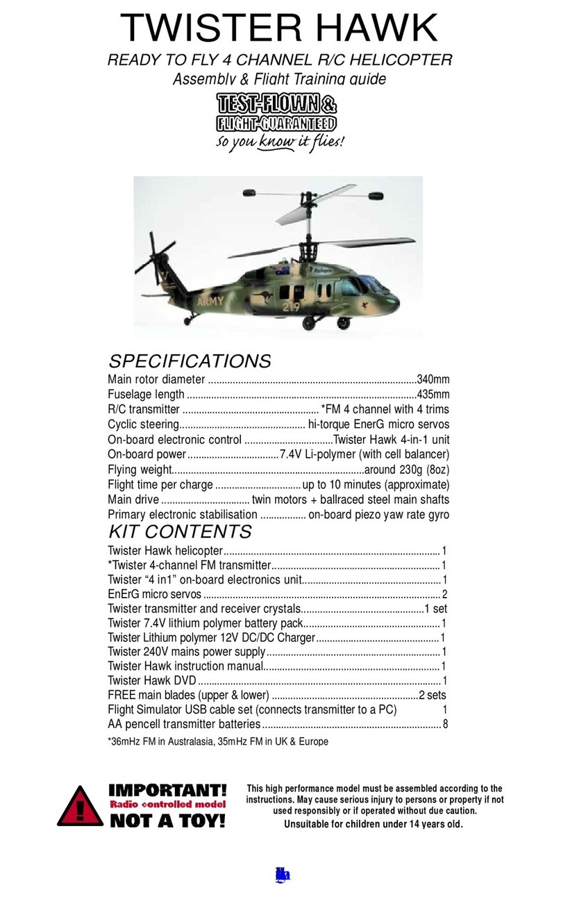
J. Perkins Twister Hawk Setup guide

J. Perkins

J. Perkins Twister Hawk Setup guide

J. Perkins TWISTER BELL 47 User manual

J. Perkins

J. Perkins TWISTER BELL 47 User manual

J. Perkins Twister 3D Storm User manual

J. Perkins

J. Perkins Twister 3D Storm User manual

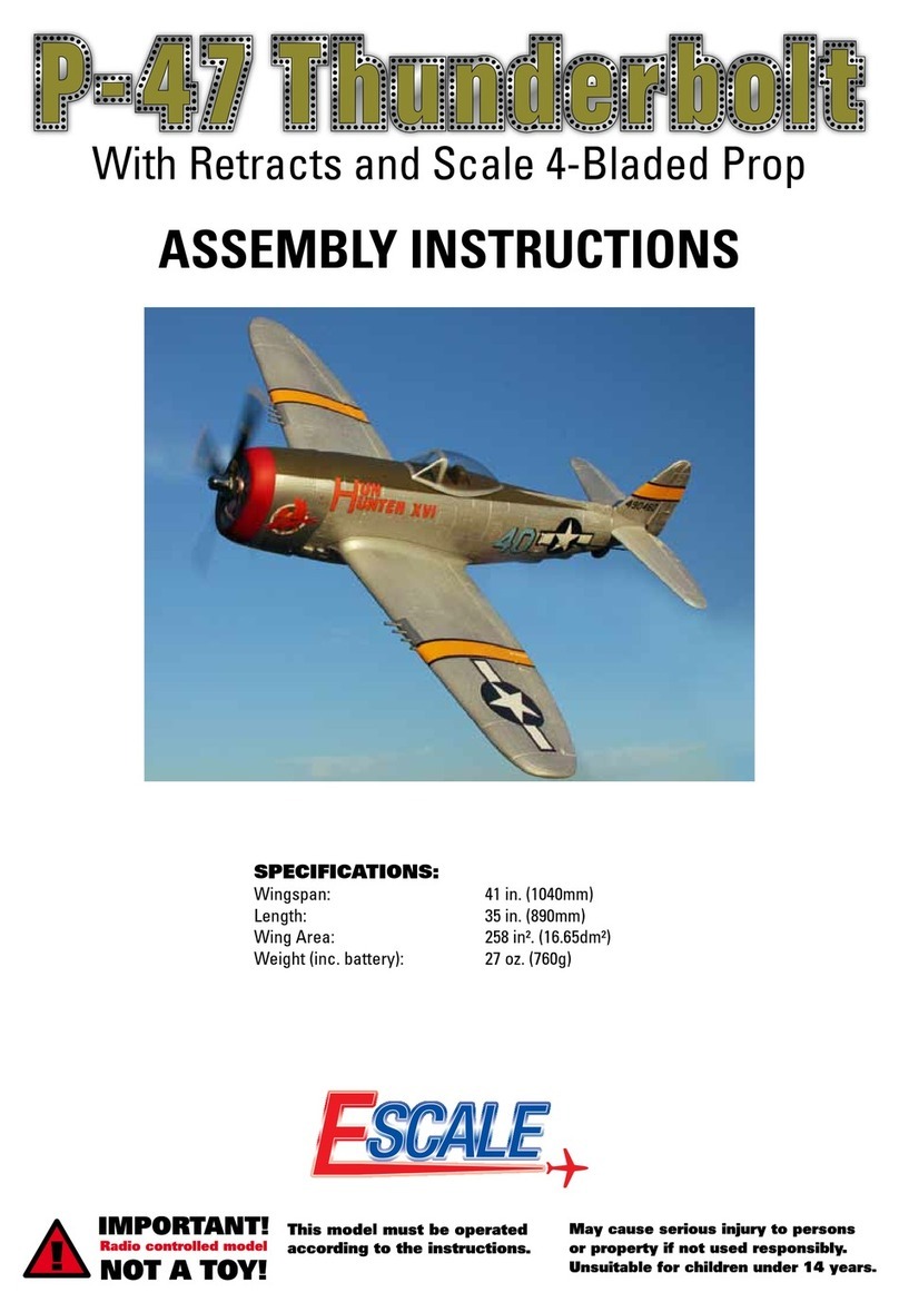
J. Perkins P-47 Thunderbolt User manual

J. Perkins

J. Perkins P-47 Thunderbolt User manual

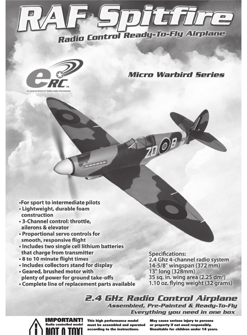
J. Perkins raf spitfire User manual

J. Perkins

J. Perkins raf spitfire User manual

J. Perkins Twister CP V2.1 User manual

J. Perkins

J. Perkins Twister CP V2.1 User manual

J. Perkins F9F Panther User manual

J. Perkins

J. Perkins F9F Panther User manual

J. Perkins Mini Twister Cam User manual

J. Perkins

J. Perkins Mini Twister Cam User manual

J. Perkins TWISTER SKYLIFT Setup guide

J. Perkins

J. Perkins TWISTER SKYLIFT Setup guide

J. Perkins TWISTER CP GOLD User manual

J. Perkins

J. Perkins TWISTER CP GOLD User manual

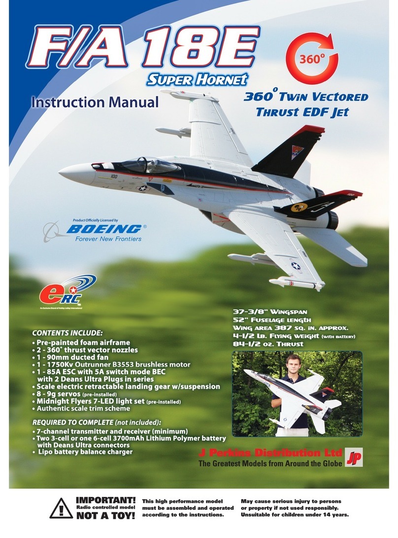
J. Perkins F/A 18E Super Hornet User manual

J. Perkins

J. Perkins F/A 18E Super Hornet User manual

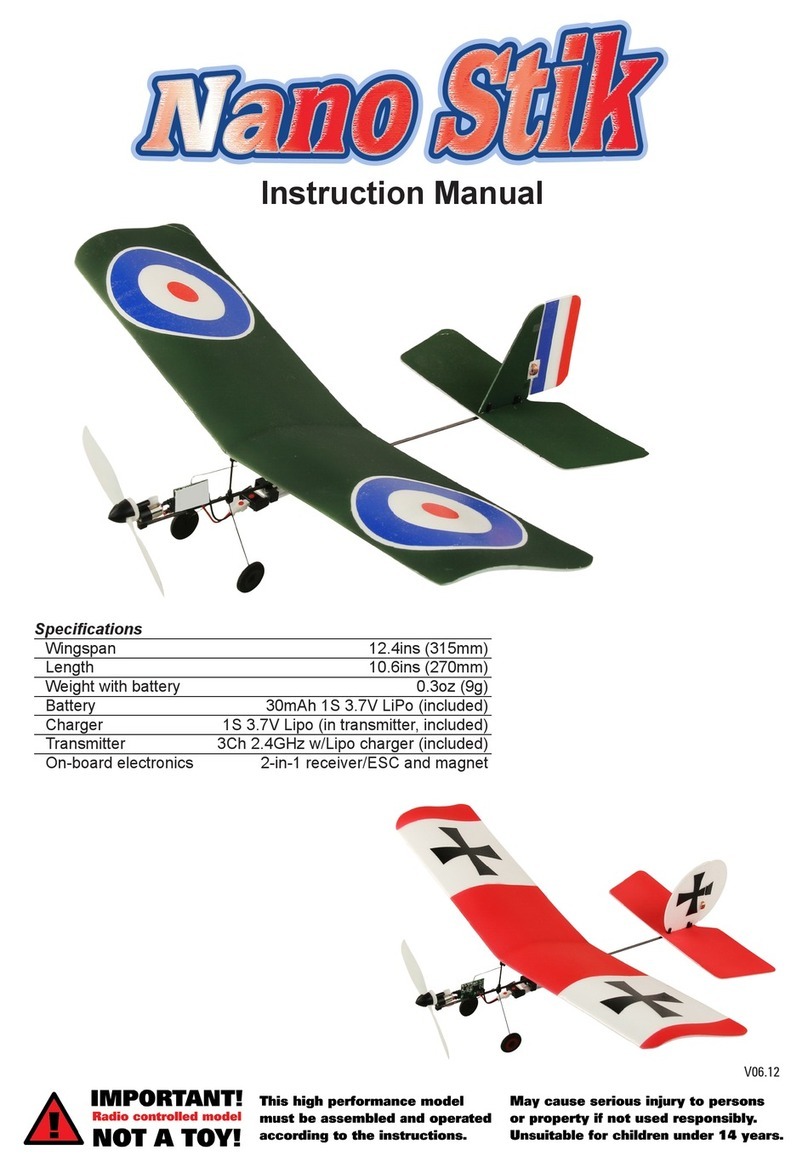
J. Perkins Nano Stik User manual

J. Perkins

J. Perkins Nano Stik User manual

Popular Toy manuals by other brands

Trix Minitrix BD D 220 operating instructions

Trix

Trix Minitrix BD D 220 operating instructions

MGA Entertainment Mooshka Goodnight Starlight Dasha manual

MGA Entertainment

MGA Entertainment Mooshka Goodnight Starlight Dasha manual

Fisher-Price THiNK & LEARN Code-a-pillar DKT39 instruction sheet

Fisher-Price

Fisher-Price THiNK & LEARN Code-a-pillar DKT39 instruction sheet

KM H-K1 instruction manual

KM

KM H-K1 instruction manual

LEGO LEGOLAND 40081 Instructions for use

LEGO

LEGO LEGOLAND 40081 Instructions for use

Robodyssey Mini Roach Assembly instructions

Robodyssey

Robodyssey Mini Roach Assembly instructions

PLAYTIVE AB-5276 Instructions for use

PLAYTIVE

PLAYTIVE AB-5276 Instructions for use

Electrotren E2592 Service sheet

Electrotren

Electrotren E2592 Service sheet

Fisher-Price P7680 instruction sheet

Fisher-Price

Fisher-Price P7680 instruction sheet

3D Hobby Shop YAK55 Assembly manual

3D Hobby Shop

3D Hobby Shop YAK55 Assembly manual

Hasbro Smokescreen 7051 instruction manual

Hasbro

Hasbro Smokescreen 7051 instruction manual

Mattel Barbie CHF54 instructions

Mattel

Mattel Barbie CHF54 instructions

TILLIG BAHN Sleeping car manual

TILLIG BAHN

TILLIG BAHN Sleeping car manual

Trix BR 74 manual

Trix

Trix BR 74 manual

Harbor Freight Tools 95641 Assembly and operation instructions

Harbor Freight Tools

Harbor Freight Tools 95641 Assembly and operation instructions

Faller 130443 manual

Faller

Faller 130443 manual

Bestway Funspeakers 34151 owner's manual

Bestway

Bestway Funspeakers 34151 owner's manual

Plantraco Sky Buddy manual

Plantraco

Plantraco Sky Buddy manual

manuals.online logo
manuals.online logoBrands
  • About & Mission
  • Contact us
  • Privacy Policy
  • Terms and Conditions

Copyright 2025 Manuals.Online. All Rights Reserved.