User manual
AKKUTEC 2412 VdS
Document page 1 / 16
0812G01B02-160422.docx
J. Schneider Elektrotechnik GmbH
Helmholtzstraße13, 77652 Offenburg · Postfach 2327, 77613 Offenburg · Werner-von-Siemens-Straße 12, 77656 Offenburg
Tel
+49
(0)
781
206
0
·
Fax
+49
(0)
781
253
18
·
[email protected] · www.j-schneider.de · Amtsgericht Freiburg HRB 470458 Geschäftsführer: Dipl.-Betriebswirtin (BA) Bettina Schneider · Dipl.-Wirt,-Ing. (FH) Rolf Anti · UST-Ident-Nr. DE142532740
DC-USV
NBPA0812G01***
VdS-Nummer G209169
0786-CPD-20873
page
1. General......................................................................................................................2
1.1 General safety notes
1.2 Short description
2Transportation and storage.....................................................................................3
3Installation and connection.....................................................................................3
3.1 Installation
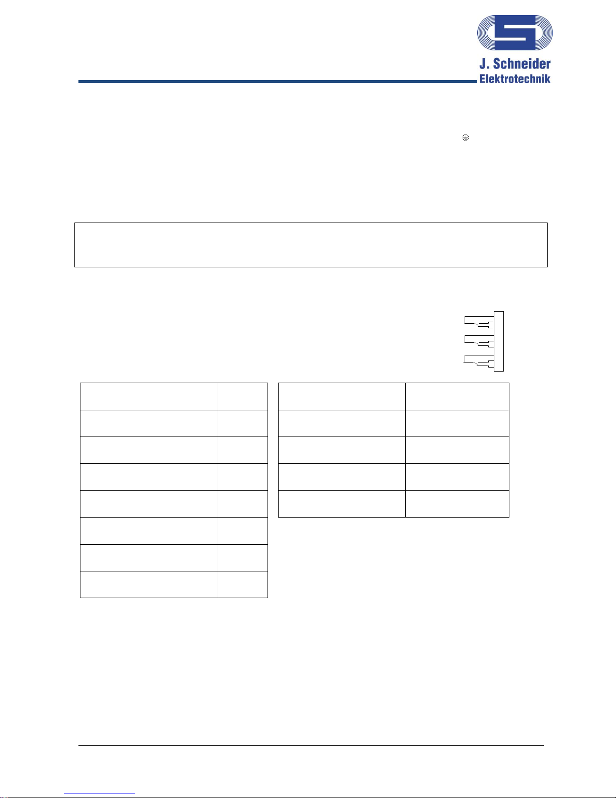
3.2 Connection
3.3 Connection lead accumulator
3.4 Connection of mains voltage
3.5 Connection load
3.6 Signal contacts
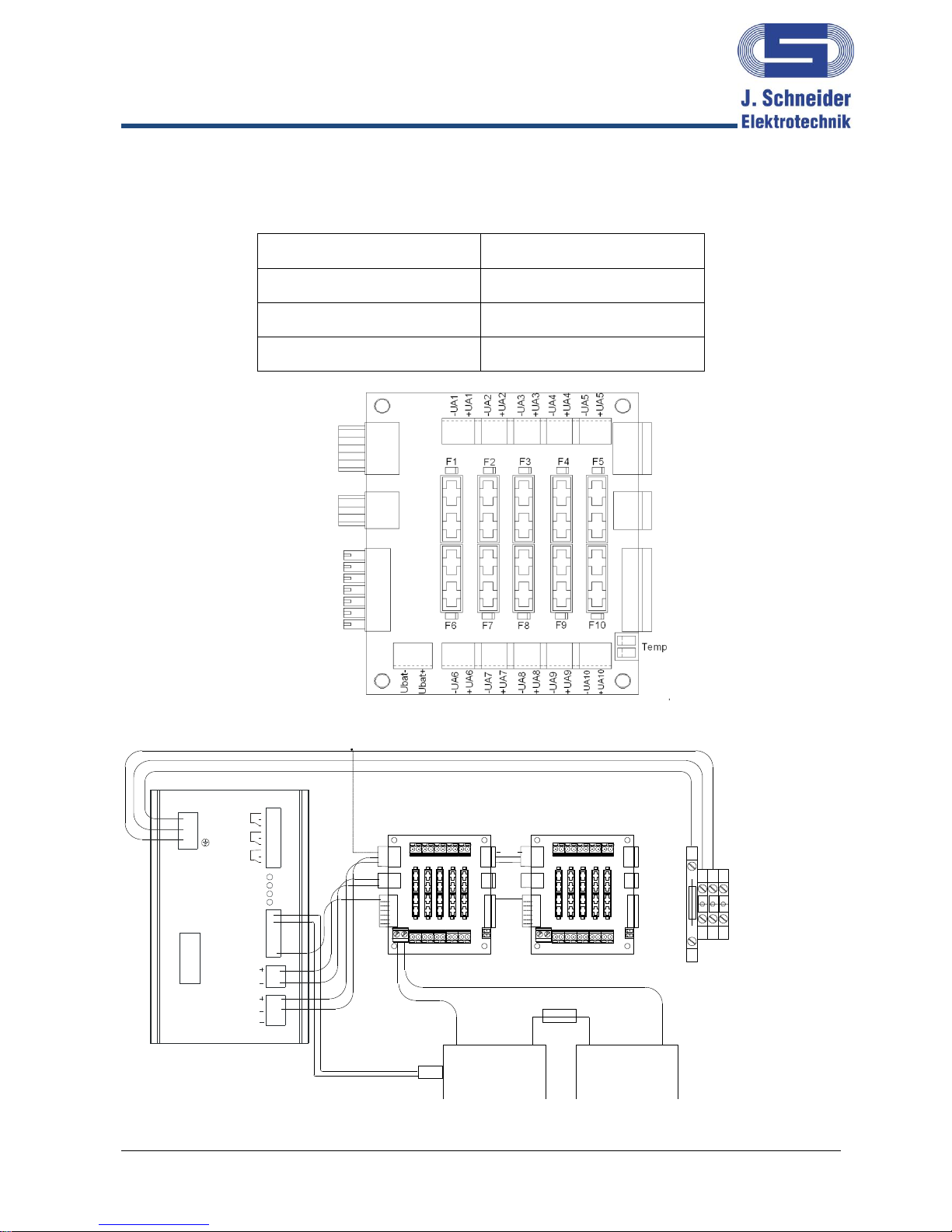
3.7 Circuit diagram
4Start-Up .....................................................................................................................9
4.1 Display and messages
5Operation ..................................................................................................................9
5.1 Mains operation
5.2 Back-up operation
5.3 Deep discharge protection
5.4 Accumulator circuit monitoring
5.5 Accumulator test
5.6 Temperature tracking (optional)
5.7 Shut-Down
5.8 Acoustic alarm transmitter (optional)
6Master/Slave-operation at parallel connection .....................................................11
6.1 Connection at Master/ Slave-operation
6.2 Signalisation at Master/Slave-operation:
6.3 Shutdown at Master/Slave-operation
6.4 Configuration Master/Slave
7Servicing ..................................................................................................................13
7.1 Testing the lead accumulators
7.2 Exchanging the lead accumulators
8Decommissioning....................................................................................................14
9Disposal ...................................................................................................................14
10 Norms and regulations ...........................................................................................14
11 Technical Data.........................................................................................................15
12 Accessories .............................................................................................................16