manuals.online logo
Brands
  1. Home
  2. •
  3. Brands
  4. •
  5. J. Strong
  6. •
  7. Automobile Accessories
  8. •
  9. J. Strong JST506BT User manual

J. Strong JST506BT User manual

FIGURE 1
Step – 1
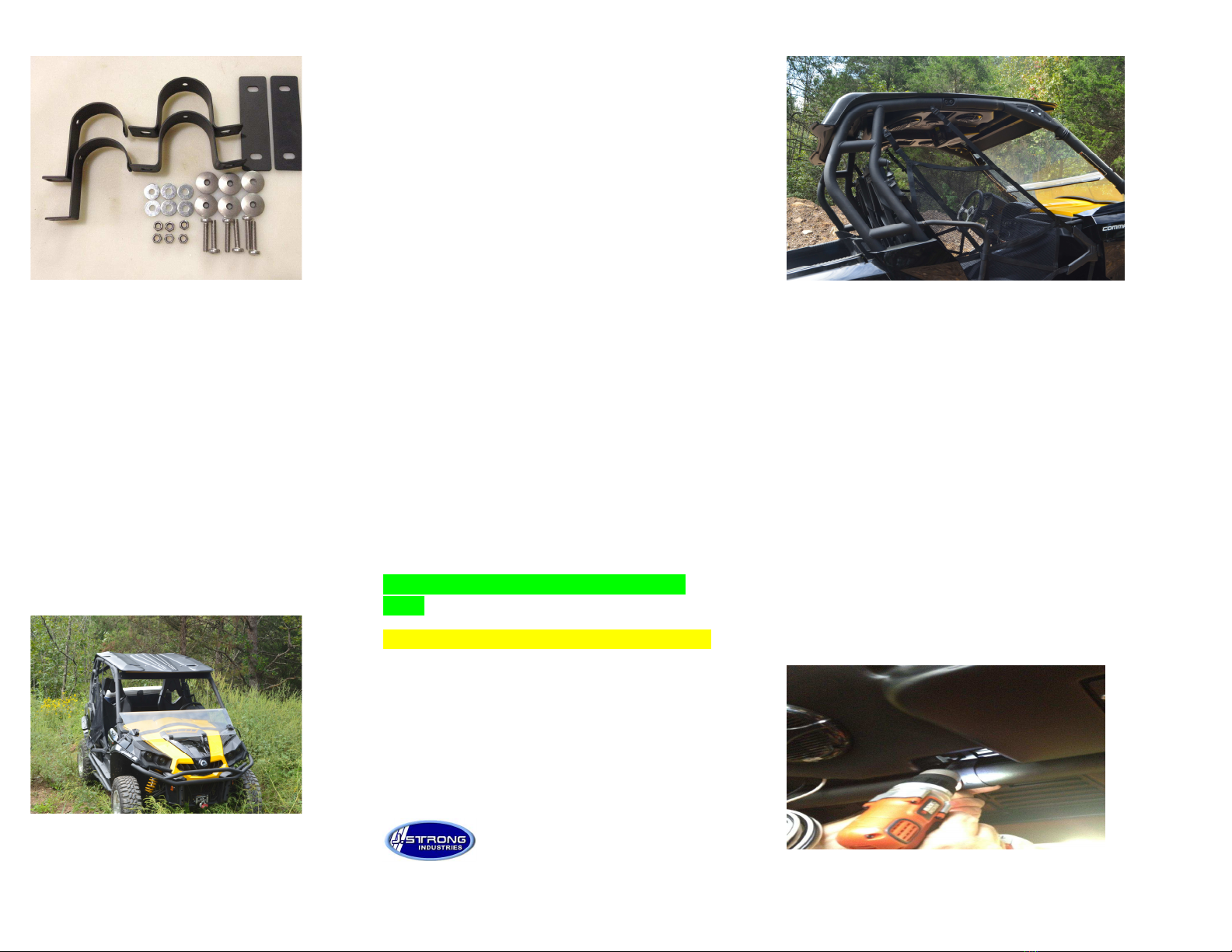
Remove Top and Hardware Pack
from Box. Inspect top and hardware
pack to confirm no missing
/
damaged
parts. (If any parts are
missing or damaged Please call -
877-444-4 47) (See Figure 1)
Step – 2
Place Top on Roll Cage and Center
Left to Right. As seen in Figure 2
FIGURE 2
JST506BT
Installation Instructions
Hardware Included
6 – M6 X 30 SS Bolt (QM2550030A20000)
6 – M6- .0 Locknut ( L2550000A20000)
6 – M6 X 8 MOD Fender Washer ( 38403)
6 – ¼ X ” SS Bonded Washer ( 2305-02035)
2 – 2” J Clamps Rear Bracket (929-973)
2 – 2” U Clamps Front Bracket (929-972)
2 – Tie Plates (929-974)
Tools Required
Drill
Phillips Head (4way) Screw Driver / Bit
3/8” Drill Bit
0mm Socket (Small Extension May be
required)
**- STEP-6 IS FOR CAN-AM COMMANDER
ONLY
** - STEP 7 IS FOR CAN-AM MAVERICK ONLY
J. STRO G I DUSTRIES
-877-444-4 47
FIGURE 3
Step – 3
Slide top forward to allow proper fitment to the roll
cage as seen in Figure 3
NOTE: Temporarily Clamp the Top to the Roll cage.
Step-4
Mount Front U-
Brackets by drilling through the top
with a 3/8 drill bit. Refer to Figure 4
for bracket
Location.
FIGURE 4
FIGURE 5
Step-5
Mount Rear J-
Brackets by drilling
through the top with a 3/8 drill bit.
Refer to Figure 5 for bracket Location
** Step-6 Commander Only
(Maveric S ip to Step 7)
Tighten all Bolts and run wiring to the
battery. White wire is (+) Positive.
Black wire is (-) Negative.
AFTER COMPLETING ALL STEPS TURN
ON THE MUSIC AND HAVE FUN.
IF IT’S NOT J.STRONG IT’S NOT STRONG
ENOUGH.
Any questions or comments please
contact us at 877-444-4 47 or visit our
website at
http://www.jstrongindustries.com
FIGURE 6
**Step-7 (Maveric Only)
Using a 3/8 drill bit, drill 2 holes in the
Top
Beside Left Rear Speaker as seen in
Figure
6
. Remove left front and rear speakers. ull
White (+) and Black (-
) wires into the top
and reroute the wiring to the two
newly
drilled holes. lace 2 snap bushings into
the
n newly drilled holes, place the two
plugs into the front snap bushings where
wires were previously ran, as seen in
Figure
7.
FIGURE 7

Popular Automobile Accessories manuals by other brands

Westin 46-23785 instructions

Westin

Westin 46-23785 instructions

Yakima EASY-OFF installation instructions

Yakima

Yakima EASY-OFF installation instructions

Prorack K998 Fitting instructions

Prorack

Prorack K998 Fitting instructions

Crux SWRVL-54 manual

Crux

Crux SWRVL-54 manual

Directed Directechs HYUNDAI1 installation guide

Directed

Directed Directechs HYUNDAI1 installation guide

Kuda-Phonebase 041160 Installation instruction

Kuda-Phonebase

Kuda-Phonebase 041160 Installation instruction

Jotto Desk 425-5005 quick guide

Jotto Desk

Jotto Desk 425-5005 quick guide

Metra Electronics Axxess CLASSII-100 installation instructions

Metra Electronics

Metra Electronics Axxess CLASSII-100 installation instructions

Innova OBD2 owner's manual

Innova

Innova OBD2 owner's manual

Yakima K668 instructions

Yakima

Yakima K668 instructions

DLS DLS POWER CAPS owner's manual

DLS

DLS DLS POWER CAPS owner's manual

Nachfolger Travel Kit user guide

Nachfolger

Nachfolger Travel Kit user guide

InPOWER ITM-133 manual

InPOWER

InPOWER ITM-133 manual

Over Armour Offroad AC-TRAIL-DRW01 Instructions for Installation and Care

Over Armour Offroad

Over Armour Offroad AC-TRAIL-DRW01 Instructions for Installation and Care

GReddy TYPE-RS BRS-610 GDB instruction manual

GReddy

GReddy TYPE-RS BRS-610 GDB instruction manual

Aldor Automotive FOR2TRSU Assembly manual

Aldor Automotive

Aldor Automotive FOR2TRSU Assembly manual

Thule 1649 instructions

Thule

Thule 1649 instructions

Saris SENTINEL user manual

Saris

Saris SENTINEL user manual

manuals.online logo
manuals.online logoBrands
  • About & Mission
  • Contact us
  • Privacy Policy
  • Terms and Conditions

Copyright 2025 Manuals.Online. All Rights Reserved.