J-Tech Digital JTD-669 User manual

1
JTD-669 | JTECH-4KM44A
4x4 HDMI 2.0 matrix

2
Thank you for purchasing this product. For optimum performance and
safety, please read these instructions carefully before connecting,
operating or adjusting this product. Please keep this manual for future
reference.
SURGE PROTECTION DEVICE RECOMMENDED
This product contains sensitive electrical components that may be
damaged by electrical spikes, surges, electric shock, lightning strikes,
etc. Use of surge protection systems is highly recommended in order to
protect and extend the life of your equipment.

3
Table of Contents
Features............................................................................................................. 4
Package Contents............................................................................................. 4
Specifications ................................................................................................... 4
Panel Descriptions ........................................................................................... 5
Connecting and Operating............................................................................... 6
Application Diagram......................................................................................... 7
Remote Control Description ............................................................................ 7
Panel Control Description................................................................................ 8
Video Switch Operation:............................................................................................. 8
Video Control: ............................................................................................................ 9
Video Switching ...................................................................................................... 9
Output Switch Control ........................................................................................... 10
Audio Control Menu: ................................................................................................ 11
Switch Output Audio.............................................................................................. 12
Audio Extraction Control........................................................................................ 12
EDID Setting Menu: ................................................................................................. 12
Preset Application: ................................................................................................... 14
Setup Interface:........................................................................................................ 15
Baud Rate Setting ................................................................................................. 15
DHCP ................................................................................................................... 16
Reboot .................................................................................................................. 16
Factory Reset........................................................................................................ 17
Query Information Interface:..................................................................................... 18
RS232 Control................................................................................................. 20
Open CommUart Assistant
....................................................................................... 20
Comport Settings: .................................................................................................... 20
Sending Port Commands: ........................................................................................ 20
Command List:......................................................................................................... 20
Web Control .................................................................................................... 21
Change IP Address of PC:..................................................................................... 21
Log in via Browser:................................................................................................... 22
Video Interface:........................................................................................................ 22
Audio Interface:........................................................................................................ 23
EDID Interface: ........................................................................................................ 24
Network Interface:.................................................................................................... 25
System Setting Interface:.......................................................................................... 26
Firmware Upgrade .......................................................................................... 27
MCU Application Layer Upgrade:.............................................................................. 27
Web Upgrade........................................................................................................... 28
WARRANTY..................................................................................................... 29

4
Dear Customer
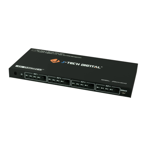
Thank you for purchasing the J-Tech Digital JTECH-4KM44A 4x4 Matrix Switcher. For
optimum performance and safety, please read these instructions carefully before
connecting, operating or adjusting this product. Please keep this manual for future
reference.
Features
HDMI 2.0 | HDCP 1.4/2.2 Compliant
Bandwidth up to 18 Gbps
Support HDR10 | HLG | Dolby Vision
4 x HDMI Input | 4 x HDMI Output | 4 x Coaxial S/PDIF Audio Out | 4 x Analog Audio Out
Control via IR Remote | RS232 | Web GUI | TCP/IP
Support PCM 2.0 | Dolby True HD | DTS-HD Master Audio | LPCM7.1 | Audio
Sampling Rate up to 192KHZ
Supports Analog and S/PDIF Audio Extraction
Supports EDID management and EDID Copy
Firmware Updates via USB
Package Contents
1).
1x JTECH-4KM44A Matrix Switcher
2).
1x 12V/2A DC Power Supply
3).
1x Remote Control
4).
1x IR Ext RX Cable
5).
5x Phoenix Connectors
6).
1x CD for Control Software & User Manual
Specifications
Operating Temperature
32°F - 104°F
Operating Humidity 5% - 90% RH (No Condensation)
Max Resolution
4K@ 60hz YUV4:4:4
HDCP Compliant HDCP 1.4 | HDCP 2.2
Output Video HDMI 1.4 | HDMI 2.0
Audio Format Supported PCM 2.0 | Dolby True HD | DTS-HD Master Audio | LPCM 7.1
RS-232 Serial Port 3-Pin Phoenix Connector
Ethernet Port (IP Control) RJ45 (Female)
IR Ext port 3.5mm (TRS Female)
USB port Micro-USB Female
Bandwidth 18 Gbps
Default IP Address 192.168.1.168
Rack-Mountable Rack ears included
Dimensions (LxWxH) 8.51” x 5.06” x 1.33”
Net Weight 1.04 lbs.
Power Consumption 14W (Max)

5
2
3
Panel Descriptions
IR Receiver Sensor
Output 1 - 4: Short press to choose output (press again to cancel); long press to
choose all outputs (long press again to cancel).
Input 1 - 4: Short press to choose input (user must choose output first); long press to
choose one input for all outputs.
PRESET: Access Presets
UP: Navigate Up through menu
LOCK: Long press to enable button lock (long press to unlock). *Note – All buttons are
non-functional except for ‘Lock’ button when lock function is enabled.
MENU: Access main menu or return to the previous menu interface
DOWN: Navigate Down through menu
ENTER: Short press to confirm selection
LCD Screen
*Note: LCD screen will enter power saving mode if a selection has not been made within
60 seconds.
1
4
5
6
7
8
9
10
Front Panel

6
Rear Panel
①Analog Audio Out (Phoenix)
②S/PDIF Audio Out (Coaxial)
③
RS232(Phoenix)
④IR-Ext
⑤Ethernet Port
⑥
DC12V/2A Power Adapter Port
⑦HDMI Output Ports
⑧HDMI Input Ports
Connecting and Operating
1.
Connect source devices to input ports via HDMI cable.
2.
Connect HDMI output ports to TV or other HDMI sink devices via HDMI cable.
3.
Optional: Connect RS232 cable from PC to RS232 port.
4.
Optional: Connect an Ethernet cable from the TCP/IP port on the matrix to
a local area network.
5.
Connect 12V Power Supply to DC/12V power port.
6.
Power on the matrix, HDMI sources and displays.

7
7
Application Diagram
Remote Control Description
Power On / Standby
M:Mute HDMI Output Audio
W: Lock Remote Control
Output 1-4 (press output 1-4 then input 1-4 for
routing)
All Outputs Show 1 Input
a. Press “ALL” Button
b. Press Desired Input Button (1-4). Desired
Input will be sent to all outputs
Turn Off Output Port
PTP button: Mirror All Inputs and Outputs
(Ex. Input 1 to output 1, input 2 to output 2, etc)
Input 1-4 (press output 1-4 then input 1-4 for
routing)
Cycle through Input Ports
Left | Up | Down | Right
1
2
3
4
5
6
8
9
10

8
***Note:
Power On / Standby: Short press for standby mode; LCD screen will show ”System
Shutdown” and TV will not display an image. Short press again to wake up from standby
mode, HDMI output returns to normal
Video switch: Output + Input (ex: Output1 + Input2 switches Output 1 to Input 2)
Mute HDMI Output Audio: Output + M (ex: Output1+M mutes Output 1 audio)
Lock Remote Control: Short press ”W” to lock remote buttons | Short press again to unlock
Turn Off Output Port: Output + X (ex: Output1 + X disables Output 1 Port | Output + X
again to enable Output Port)
Cycle Through Input Ports: Output + “<” or “>”; (ex: All + “<” cycles backwards through
source signals on ALL connected displays. Function automatically skips input port if no input
signal is detected)
Panel Control Description
Video Switch Operation:
Signal routing includes 4 input and 4 output channels that can be configured according to
the desired effect to form a 1×4 through 4×4 matrix. Users can route any input signal to any
output port or all output ports.
Operation Format - "Output Port" + "Input Port"
Examples:
1.
Route Input 4 to Output 1
Operation: Press Output 1 + Input 4
2.
Route Input 2 to Output 1, 2 & 3
Operation: Press Output 2, Output 1, Output 3 + Input 2
3.
Route Input 4 to All Outputs
Operation: Press ALL + Long Press Input 4

9
Video Control:
There are 2 sub-menus in the Video Menu: Switching | On/Off
Video Switching
Operation:
①
Select "Video" in the main menu & press "ENTER" button
②Press “Up and Down” buttons to highlight “Switching” sub-menu
③Press "ENTER" to enter the “Switching” sub-menu
④
Press “Up and Down” buttons to select “Output 1 – Output 4” or “All”. Your current
selection will be highlighted in white
⑤Press "ENTER" to enter the next sub-menu
⑥Press the “Up and Down” buttons to select the desired input. Your current
selection will be highlighted in white.
⑦Press "ENTER" button to complete video switching

10
Output Switch Control
You can enable or disable any output port or all output ports. Output ports are enabled by
default. Operation:
①In the main menu, select "Video" and press "ENTER" button
②Press “Up and Down” buttons to select “On/Off”
③Press "ENTER" button to enter the next sub-menu
④Press “Up and Down” buttons to select “Output 1-4”
⑤Press "ENTER" to enter the next sub-menu
⑦Press the “Up and Down” buttons to select “Off” or “On”
⑧Press "ENTER" button to apply your selection

11
Audio Control Menu:
There are 2 sub-menus in Audio Control menu: Line Out | De-Embed

12
Switch Output Audio
“Line out” function allows users to enable or disable HDMI Output audio while
maintaining HDMI Output video.
Operation:
①Select “Audio” in main menu and press the “ENTER” button.
②Press “Up and Down” buttons to select “Line Out” and press the “ENTER” button. Select
“Output 1-4” or “All” via “Up and Down” buttons. Press “ENTER” to choose ”On” (audio
enabled) or “Off” (audio disabled).
③Example: Mute audio of TV connected to HDMI Output 1
Operation: “Audio” + “ENTER” > “Line Out” > “Output1” > “Off” + “ENTER”
Audio Extraction Control
“De -Embed” function allows users to enable or disable Analog and Digital Audio Output
ports.
Operation:
①Select “Audio” in main menu and press the “ENTER” button.
②Press “Up and Down” buttons to select “De -Embed” and press the “ENTER” button.
Select “Output 1-4” or “All” via “Up and Down” buttons. Press “ENTER” to choose ”On”
(audio enabled) or “Off” (audio disabled).
③Example: Disable audio extraction of HDMI Output 1
Operation: “Audio” + “ENTER” > “De-Embed” > “Output 1” > “Off” + “ENTER”
EDID Setting Menu:
EDID Management: User EDID | Built-in EDID | Copy EDID Function
*Note - The default EDID profile is “Default1”
Default1 4K60 444-LPCM: 2.0, HDR: HLG Default2 4K60 420-LPCM: 2.0, HDR: None
Default3 4K30 444-LPCM: 2.0, HDR: None
Default4 1080P60 444-LPCM: 2.0, HDR: None

13
Example: Apply EDID profile “Default 1” to HDMI Input 1
Operation:
①Select “EDID” in the main menu and press the “ENTER” button
②Press the “Up and Down” buttons to select “Input 1”
③Press the "ENTER" button to enter the next sub-menu
④Press the “Up and Down” buttons to select “Default1” and press “ENTER” to apply
the EDID profile
⑤EDID Profile settings (max resolution | audio format | HDR) will be shown when the
EDID profile is highlighted.

14
Preset Application:
“Preset” function allows users to save the current audio video routing, EDID settings and
system settings. The JTECH-4KM44A supports 8 presets that can be set via web GUI, RS232
commands or front panel buttons.
Preset Control Interface has three sub-menus:
Call Scene | Save Scene | Clear Scene
Operation:
①Select “Preset” in the main menu and press the ”ENTER” button
②Save Preset: Select Save > Highlight desired Preset (Preset 1 through 8) > “ENTER”
③Call Preset:Select Call > Highlight desired Preset (Preset 1 through 8) > “ENTER”
④Clear Preset: Select Clear > Highlight any of the previously saved Presets (Preset 1
through 8) > “ENTER”

15
Setup Interface:
The Setup interface allows users to set serial port baud rate, enable DHCP, reboot the device and
apply a factory reset.
Baud Rate Setting
4 Baud Rate Settings: 9600 | 19200 | 57600 | 115200 (default)
Example: Setting Baud Rate to 9600
Operation:
①Select “Setup” in the main menu and press the “ENTER” button
②Press the “Up and Down” buttons to select “Baud”
③Press “ENTER” to enter the next sub-menu
④Press the “Up and Down” buttons to select “9600”
⑤Press “ENTER” to apply the setting change

16
DHCP
DHCP On: Dynamic IP address
DHCP Off(default):Static IP address
DHCP Operation:
Select “Setup” in main menu and press the “ENTER” button
②Press the “Up and Down” buttons to select “DHCP” setting
③Press “ENTER” to enter the next sub-menu
④Press “Up and Down” buttons to select “On”
⑤Press “ENTER” to enable DHCP & to allocate IP address automatically
Reboot
Reboot device
Operation:
①Select “Setup” in main menu and press the ”ENTER” button
②Press the “Up and Down” buttons to select ”Reboot”
③Press “ENTER” to enter the next sub-menu
④Press the “Up and Down” buttons to select “Yes”
⑤Press “ENTER” to begin rebooting the device

17
Factory Reset
“Factory Reset” is a function that allows the JTECH-4KM44A to revert back to its initial factory
settings. There are two factory settings:
1. Factory Common: Factory reset for AV routing, EDID, audio line out and de-embed
settings and device setting (IP address can’t be reset with the “Factory Common” reset).
2. Factory All: Factory reset for AV routing, EDID, audio line out and de-embed
settings, device settings, presets and device name.
Example: Factory All Reset
①Select “Setup” in the main menu and press the ”ENTER” button
②Press the “Up and Down” buttons to select “Factory”
③Press “ENTER” to enter the next sub-menu
④Press the “Up and Down” buttons to select “ALL” and press the “ENTER” button
⑤Press the “Up and Down” buttons to select “Yes” and press the “ENTER” button

18
Query Information Interface:
Query IP and System Information
System Interface: Query company name, device name and version
information
IP Interface: Query device IP address, MAC address and DHCP status
Operation:
①Select “INFO” in the main menu and press the ”ENTER” button
②Press the “Up and Down” buttons to select “System” or “IP”
③Press “ENTER” to enter the next sub-menu here system or IP information is available

19

20
RS232 Control
Open CommUart Assistant
Comport Settings:
Choose correct COM port that connects to the PC in the parameter configuration area
Baud Rate:
115200 bps (Default)
Parity:
None
Data Bit:
8 bit
Stop Bit:
1 bit
Sending Port Commands:
Command List:
1). All commands start with “#”
2). “_” the underline cannot be omitted.
3) Command head, Parameter and target need to have one “SPACE”.
The following table is only an example. Please refer to the list of instructions.
Type Format Value Regulation
Command head #cmd without
Explain Can be used to search command, after receiving command, the system will
feedback all open command format fields
Example1 #cmd
Search all open command
This manual suits for next models
1
Table of contents
Other J-Tech Digital Switch manuals

J-Tech Digital
J-Tech Digital JTD-2996 User manual

J-Tech Digital
J-Tech Digital JTD-3003 User manual

J-Tech Digital
J-Tech Digital JTD-2887 User manual

J-Tech Digital
J-Tech Digital JTD-3004 User manual

J-Tech Digital
J-Tech Digital JTECH-NS24 User manual

J-Tech Digital
J-Tech Digital JTD-2886 User manual

J-Tech Digital
J-Tech Digital JTECH-4KPIP0401 User manual

J-Tech Digital
J-Tech Digital JTECH-BS31 User manual

J-Tech Digital
J-Tech Digital JTD-2874 User manual

J-Tech Digital
J-Tech Digital JTD-BT-Plug1x1 User manual