j3 competition kosmic Manual

By:
8233 Oliver Road – Erie, PA 16509
P – 814.864.1846
F – 814.866.2697
E – Info@J3Competition.com
W – J3Competition.com
2008
V.0108
KNOWLEDGE PACKET

J3 Competition Inc. – Kosmic Owner’s Knowledge Packet 2 | P a g e
Index
1. Seat Installation
2. Front-Track Adjustments
3. Rear-Track Adjustments
4. Caster/Camber Adjustments
5. Front-Ride Height Adjustments
6. Ackerman and Steering Adjustment
7. Rear-Ride Height Adjustments
8. Tire Pressure
9. Axle Chart/Stiffness
10. Tuning Bars
11. Rear Hubs
12. Braking System
13. Basic Wet Weather
14. Conclusion

J3 Competition Inc. – Kosmic Owner’s Knowledge Packet 3 | P a g e
1. Seat Installation (100 and 125cc)
A (mm) Dimension………………………………..610mm
B (mm) Dimension………………………………..605mm
C (mm) Dimension………………………………..220mm
G (mm) Dimension………………………………..10cm
-If the driver is taller, measurements A and B can be increased by up to 10mm each,
while reducing dimension C by 5mm.
-If the track is very ‘Green’ lacking rubber all dimensions can be changed as well. Often
time dimensions A and B can be increased by 20-25mm in order to increase the effective
weight percentage on the rear of the chassis, thus increasing the chassis grip. This will
increases the chassis effectiveness when the driver is applying the power. In low grip
conditions the seat can also be raised higher by increasing dimension G from 10cm to 11-
11.5 cm. This change will effectively increase the chassis ‘Side Bite’ allowing the
chassis to work the tires more.
Part Number
Product Description
0037.FP
FLAT BOTTOM SEAT
-
FIBERGLASS
0037.00
STANDARD SEAT
-
FIBERGLASS
1A. Ballast (Weight Mounting)
J3 recommends using OTK weights, either 1 Kg (2.2 lbs) or 3 Kg (6.6 lbs). Part
Numbers for both items are: (PN 0275.03) and (PN 0275.01) When fastening the weights
to the seat use both provided holes on the weights with the proper hardware purchased
through J3 Competition. Check with the organization(s) you are competing with to
insure all rules are met. For general balance of the chassis depending upon how much if
any weight you need to mount, it should be placed opposite of the engine and below the
seat on the front edge that contours the driver’s legs. This will provide for a good starting
point.

J3 Competition Inc. – Kosmic Owner’s Knowledge Packet 4 | P a g e
1B. Rear Seat Struts
Each Kosmic Kart is supplied with two (2) supplemental seat struts, one (1) for each side.
The extra seat struts are designed to be fixed atop the rear axle cassette and then fastened
to the seat with the provided hardware. A good place to start is using one (1) on each
side. Many drivers prefer to use two (2) on each side, which will effectively force more
direct-pressure from the driver’s weight transfer on the rear tires. This will consequently
improve grip to the rear of the chassis.
By removing seat struts you allow for the rear of the chassis to release and spring off the
track easier. This can be an added benefit when attempting to improve the chassis
performance during corning. Be careful though, by removing seat struts, the initial
cornering may improve, but the potential to create an over-steer on exist will become
more prevalent as well as the overall balance of the chassis.
Part Number
Product Description
0006.280
SUPPLEMENTARY SEAT'S SUPPORT 280 mm
0006.300
SUPPLEMENTARY SEAT'S SUPPORT 300 mm
0006.320
SUPPLEMENTARY SEAT'S SUPPORT 320 mm
0006.340
SUPPLEMENTARY SEAT'S SUPPORT 340 mm
0006.380
SUPPLEMENTARY S
EAT'S SUPPORT 380 mm
0006.400
SUPPLEMENTARY SEAT'S SUPPORT 400 mm
0007.340
SUPPLEMENTARY BENT SEAT'S SUPPORT
340 mm
J3 has several lengths of seat struts, so don’t rush it, get the right size!

J3 Competition Inc. – Kosmic Owner’s Knowledge Packet 5 | P a g e
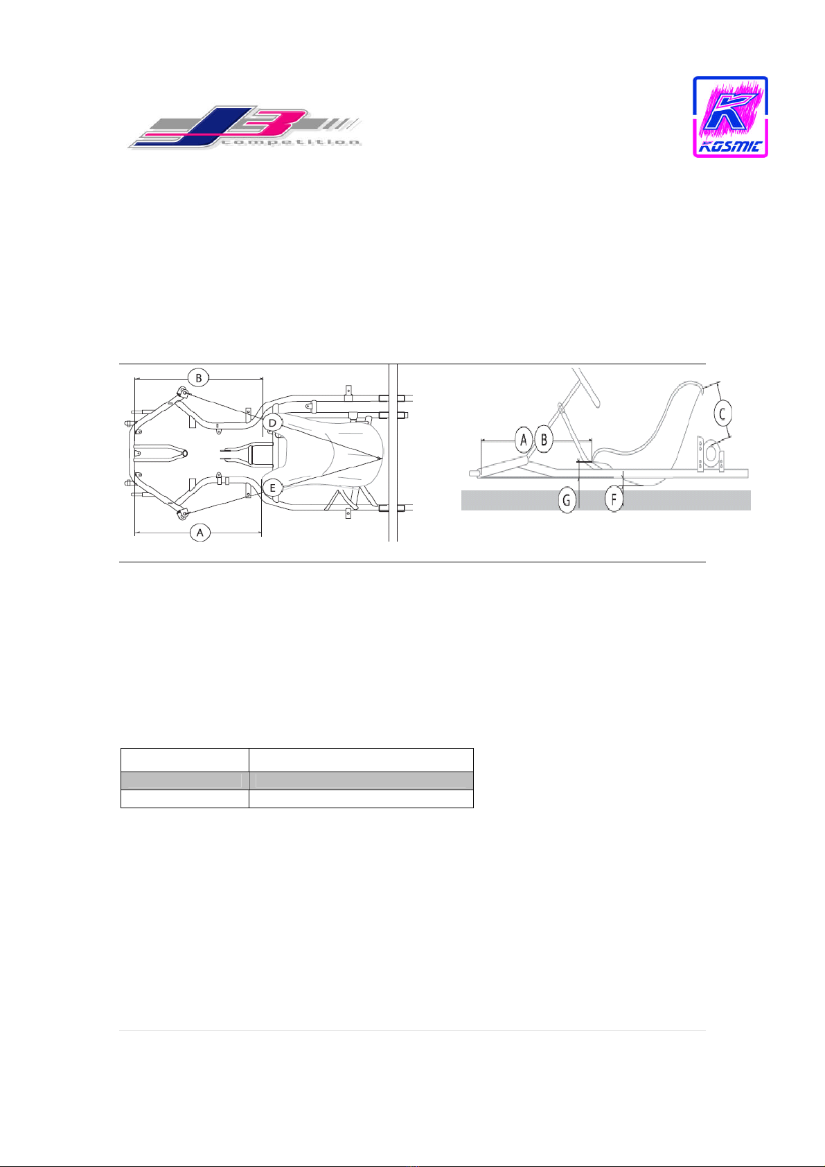
2. Front Track Adjustment
Nearly all Post-2005 Kosmic Racing Karts are sold with HST front stub axle, which has a
25mm stub in order increase the chassis front-end grip or effectiveness.
The recommended front width is to use 3-5mm spacers on the inside of the hub (Standard
90mm HST Hub). If the track has less grip a narrow front track will improve the chassis
initial reaction, however, this may cause the chassis to lose performance on longer
corners. A track with medium to high grip often times requires a wider front track width
in order to increase the chassis weight transfer. This also helps the chassis to be more
effective on longer corners when more driver input is often times required to keep the
speed up.
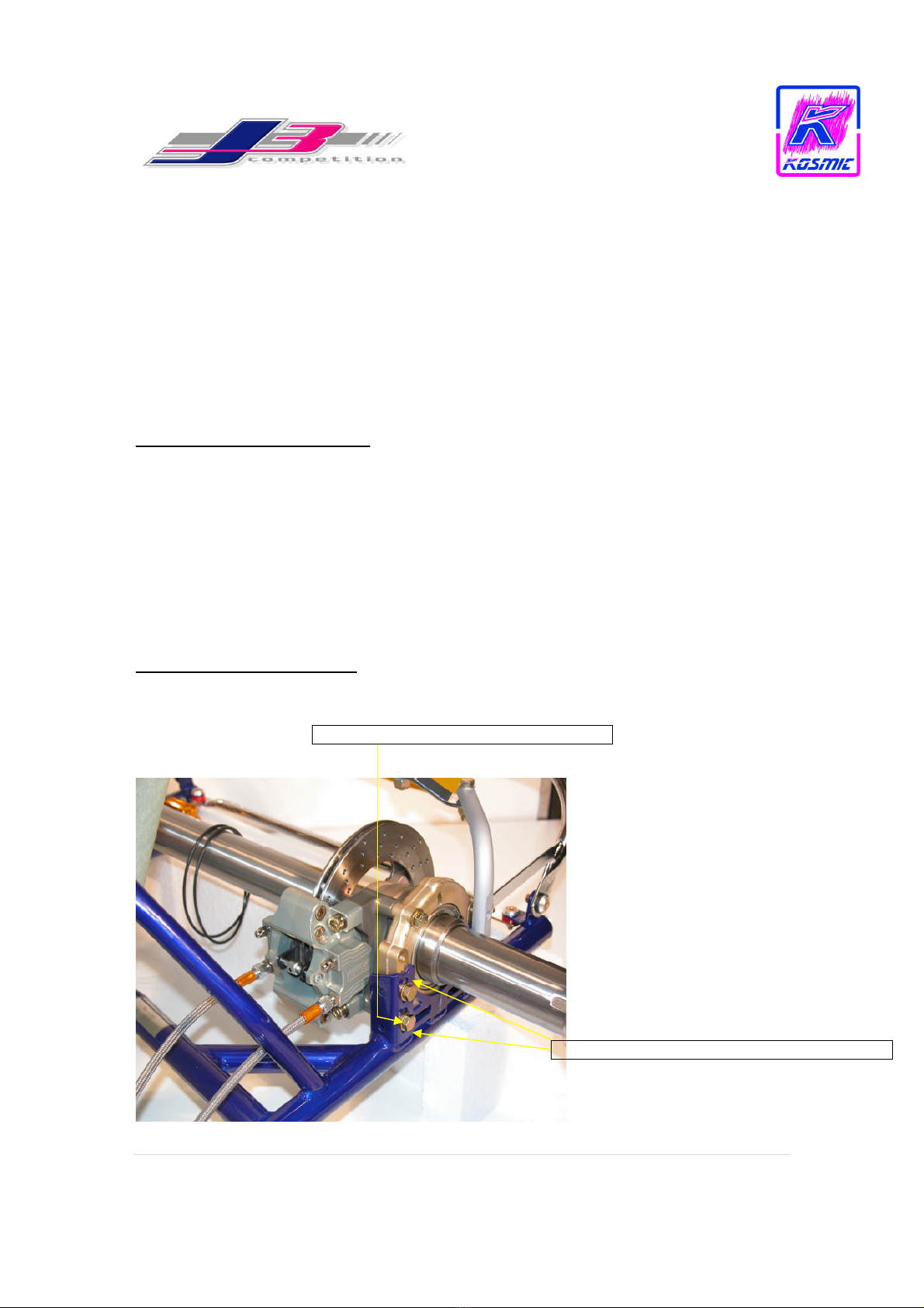
3. Rear Track Adjustment
We recommend always starting with the standard OTK 92mm rear hubs. Typically we
will start the rear track at the maximum.
- For the senior divisions this will be 55” and for the junior divisions this will be 53 ½”.
(Measured form outside rear wheel to outside rear wheel). From this point the only real
movement is to narrow the rear track.
- By narrowing the rear track of the chassis while leaving the front track untouched the
chassis will become more effective at releasing the inside rear tires during cornering.
This can initially improve the chassis performance as well as through the entire corner.
However, as grip levels change a narrow rear track can also create too much ‘Side Bite’
thus, giving the chassis too much grip in the middle of the corner and decreasing its
effectiveness. It is also recommended when the grip levels are low to test the rear track
width narrower due the potential increase in ‘Side Bite’ from the tire. Rear width can
sometimes be complicated in regards to the effects it has on the chassis performance,
therefore, make minuet changes when adjusting. And one of the major factors with rear
width is chassis balance ‘Feel’. Some drivers do not like to drive on a chassis with a
narrower rear track width, so know your driver.
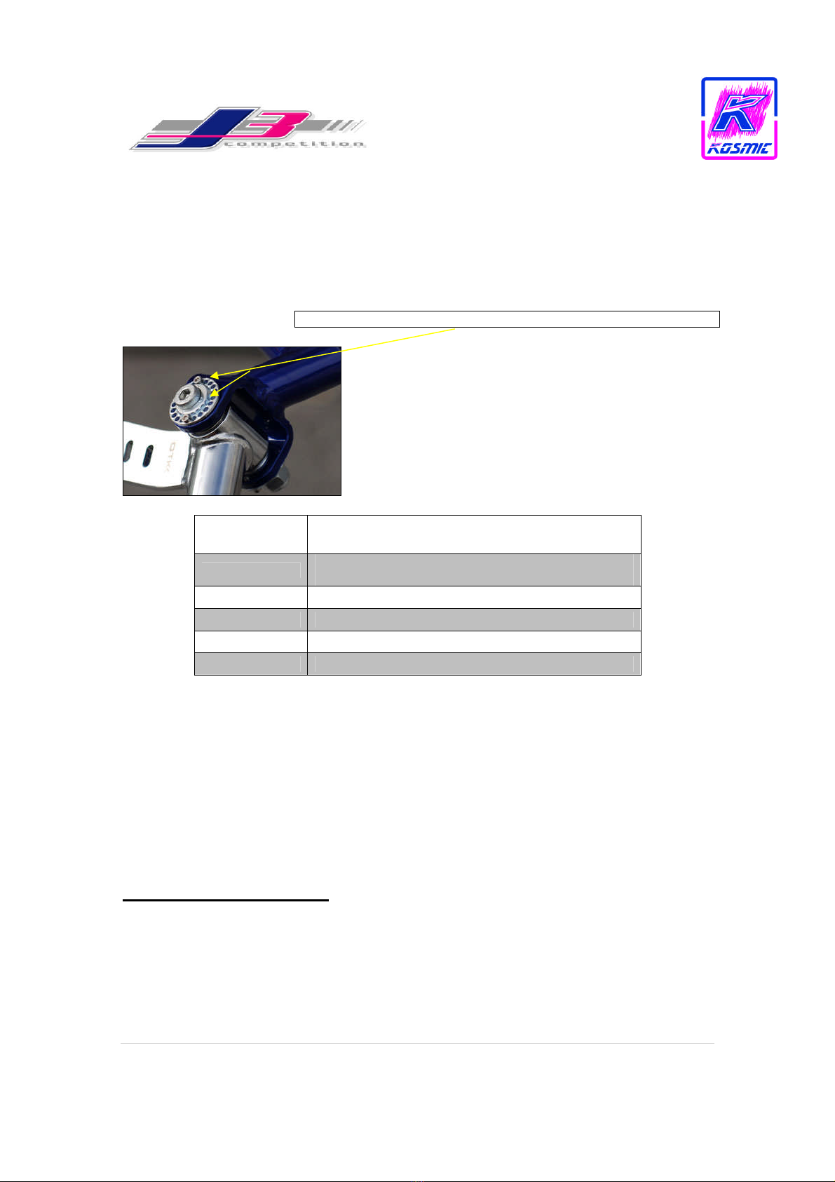
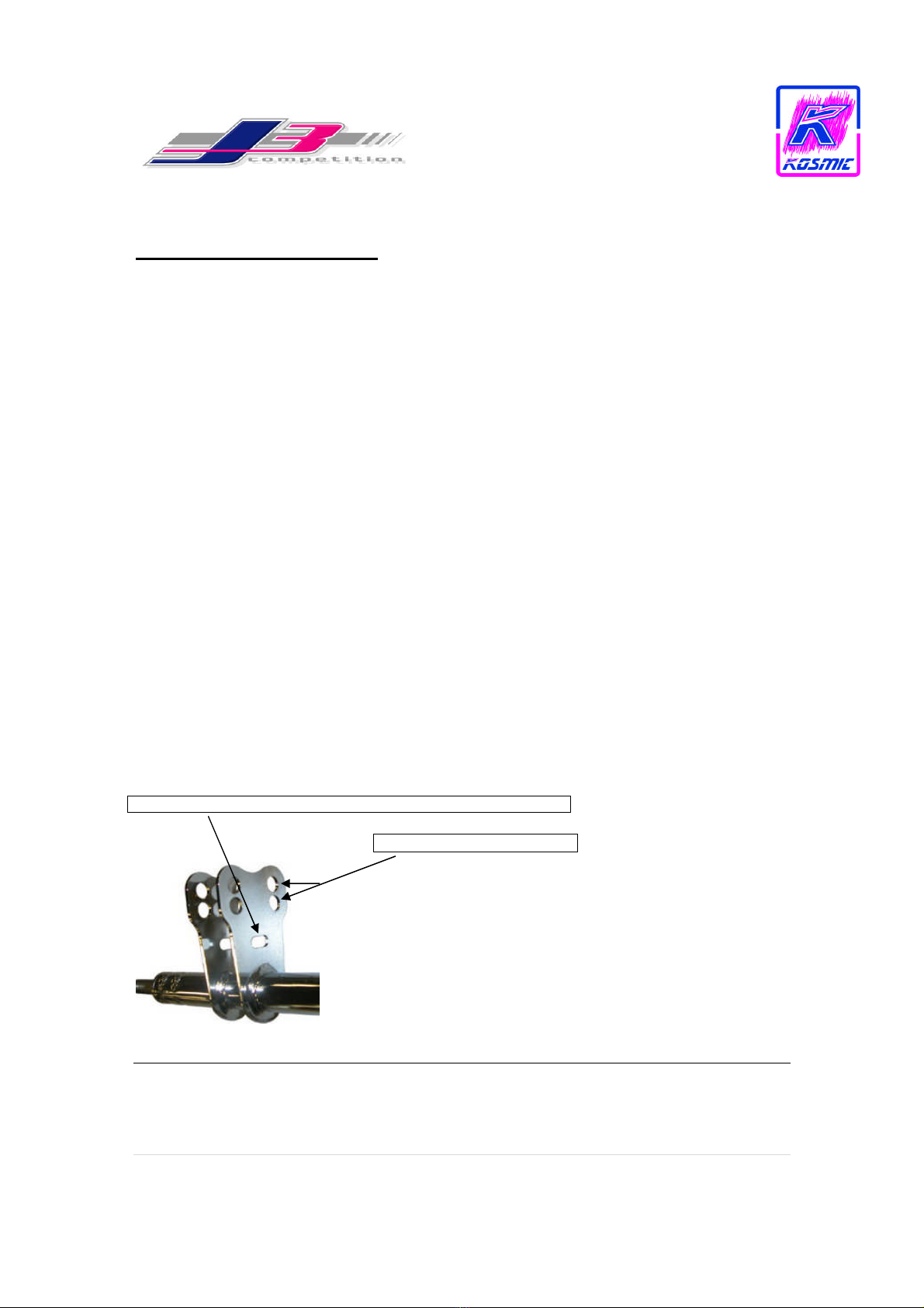
4. Caster / Camber adjustments
Caster and Camber can be adjusted at the front-end of the chassis. Depending on which
model Kosmic Racing Kart you have, there will be either 4-position ball bearing
adjustment, 4-position non-bearing eccentric either in D.8mm or D.10mm, or Post-2007
20-position ball bearing adjustment.
J3 recommends starting with full caster, which can be attained with the top eccentric
arrow facing forward and the bottom eccentric arrow facing backwards. This will give
the front-end maximum grip from a caster perspective and can possibly make the chassis
more difficult to turn as well. This is the most often setup regarding the caster position.

J3 Competition Inc. – Kosmic Owner’s Knowledge Packet 6 | P a g e
The eccentrics can be rotated to reduce the amount of caster, which will make the chassis
easier to steer and it will remove front-end grip as well. The Front-end geometry can
effect the chassis in many different ways as well depending upon the track conditions.
We recommend keeping it basic until you are familiar and comfortable making these
changes to your chassis.
2008 Kosmic Eccentric! Notice the Added Adjustment Holes!
Part
Number Product Description
0211.D0KIT
COMPLETE H
ST EXCENTRIC BUSH D.22
-
10 New
-
2008
0211.C0
INTEGRAL EXCENTRIC BUSH HST
0212.C0
INTEGRAL CONCENTRIC BUSH HST
0212.A0KIT
COMPLETE CONCENTRIC BUSH D.22
0211.A0KIT
COMPLETE EXCENTRIC BUSH D.22
5. Front-End Ride Height Adjustments
The Kosmic Racing Kart has three (3) washers that are placed between the stub axles and
the ‘C’ on the Front-end of the chassis. Two (2) of the washers are special 4mm thick
washers (PN 0215.00) and one (1) standard 1.5mm thick washer (PN RP 10x16x1.5). By
altering these washers you will be effectively changing the front ride height. The chassis
comes standard with one 4mm washer on top of the stub axle and the remaining washers
below the stub axle. This is a recommended starting position at all venues.
Raising the Front Ride Height
This is accomplished by placing washers from the bottom of the stub axle and placing
them on top of the stub axle. This has a positive effect on the entire chassis when the grip
levels increase and the chassis begins to understeer. Essentially the front ride height has
been increased so, when the steering wheel is turned the inside tire is pushed/forced

J3 Competition Inc. – Kosmic Owner’s Knowledge Packet 7 | P a g e
further into the track thus giving the driver a more positive feel (Front-Grip) and it will
result in a better handling chassis.
Lowering the Front Ride Height
The process for lowering the front ride height is the exact opposite as raising the front
ride height. The advantages here are that the front-end will feel ‘lighter’ while losing
some of its efficiencies. This can also sometimes be good on high grip tracks where the
driver has troubles driving on the higher grip.
*Front-End ride height adjustments can make a big difference if applied correctly; however, this adjustment
is best saved after other adjustments have been made to your Kosmic
6. Ackerman and Steering Adjustments
Kosmic Racing Kart’s have two (2) different types of steering columns both are 47cm.
The standard steering columns part number is (PN 0005.BA). The pitman arm or
mounting plate on the column has two (2) locations for fixing the tie rod tubes. The
standard and most often used fixing points are the lower set of holes, this gives maximum
Ackerman setting. When the tie rod tubes are located in the upper holes, Ackerman has
essentially reduced. Reducing the Ackerman will effectively make the steering lighter
and easier for driver physically; however, this will also reduce the radius at which the
front wheels turn making the front end less effective and responsive to input from the
driver throughout the turning process.
The second steering column available in 47cm is (PN 0005.F0). The pitman arm on this
column is longer, thus moving both sets of holed further away from the column, which
increases the grip and responsiveness of the chassis front-end.
! Notice the ‘Slot’! – This indicates the 47cm column with added Ackerman
! Notice the two sets of holes!

J3 Competition Inc. – Kosmic Owner’s Knowledge Packet 8 | P a g e
7. Rear Ride Height Adjustments
Kosmic Karts that have been produced from 2006 and beyond are equipped with a three
(3) position rear carriage adjustment. This is a nice feature with gives the owner ample
room to adjust the rear axle of their chassis. Each chassis comes standard with the axle
placed in the center position of holes. We highly recommend starting with the rear ride
height in the center and adjusting as needed once at the track. Typically the adjustments
here are not very frequent, however, when adjustments are made and in the right direction
positive gains will be found on the stopwatch.
Lowering the Rear Ride Height
This essentially means raising the axle to the top set of holes, which will conversely
lower the chassis position to the track surface. The typical reasoning behind this move is
to ‘free’ the back of the chassis, therefore, reducing the grip level. How does this work?
Essentially by doing so you have reduced the chassis effort to release or lift the inside
rear tire during cornering, which can be crucial in optimizing a racing Karts performance
(Note: Lifting the inside rear tire too much, will cause more negative problems than being a benefit)
The benefit of this move will be noticed under braking also, with the chassis closer to the
track surface, general braking will result in a less nervous chassis.
Raising the Rear Ride Height
This is an option than can yield effective results, but rarely. This change will increase the
chassis rear grip level. ! Notice the chassis is in the center position!
! Notice the additional holes for adjustment!

J3 Competition Inc. – Kosmic Owner’s Knowledge Packet 9 | P a g e
8. Tire Pressures
Class Compound/Make Cold Hot
Cadet Bridgestone YHC Vary 12.5psi / .85 Bar
100cc Junior Bridgestone YHC Vary 12.5psi / .85 Bar
TaG Senior Bridgestone YHC Vary 12.5psi / .85 Bar
ICA Bridgestone YJB Vary 11.5psi / .75-.8 Bar
125cc/KZ/ICC Bridgestone YJB Vary 11.5psi / .75 Bar
General rule: The higher the tire pressure is started out at, the quicker the tire will reach
its optimum pressure. This will also cause the tire to have a decreased window of
effectiveness. Therefore, in longer races it is better to start off at a lower pressure giving
the tire a longer window of optimum operating time.
9. Axle Chart and the effectiveness
Axles are very much talked about regarding tuning a Kart and rightfully so. OTK
produces six (6) axles for the 100cc category and five (5) for the 125cc gearbox category.
OTK Type ‘N’ is the standard axle and medium stiffness for the entire range. This axle is
also what each chassis comes standard with from the factory.
Which is the best axle to use when? Generally the consensus is that a softer axle (Type
U) will free the chassis letting it operate more freely around the track. This may be true
in some instances but typically not with the OTK material. Typically it is recommended
to use a harder axle (Type H or HH) when the grip levels increase. Softer axles are
recommended more for use when the grip levels are low. Why is this true? This holds
true mainly due to the fact the chassis are made of soft 30mm tubular steel. With a soft
chassis and a softer axle you will essential create the tire to work more creating “Side
Bite” or the sidewall of the tire to rollover. This will cause the chassis to ‘Hop’ and
therefore lose its effectiveness throughout the race. Keep with the ‘N’ axle; we use this
axle 80% of the time and as the grip level increase the ‘H’ will work for your needs.
Remember that the axle doesn’t simply work outside the chassis, it also creates balance
between the frame rails, and therefore, increased stiffness on your axle selection will give
the chassis more balance as well.
*Axle Chart provided on the following page

J3 Competition Inc. – Kosmic Owner’s Knowledge Packet 10 | P a g e
Axle Chart
Type
Size
Model
SOFT
HARDNESS
HARD
Code
E50x1030 DD 0054.G0E
U50x1030 DD 0054.G0U
Q50x1030 DD 0054.G0Q
N50x1030 DD 0054.G0N
H50x1030 DD 0054.G0H
HH 50x1030 DD 0054.G0HH
U50x1030 GB 0054.H0U
Q50x1030 GB 0054.H0Q
N50x1030 GB 0054.H0N
H50x1030 GB 0054.H0H
HH 50x1030 GB 0054.H0HH
10. Tuning Bars (Front Torsion Bars)
Each chassis is supplied with a ‘Flat’ steel front torsion bar. This bar can be replaced
with three (3) additional round 30mm bars made of different wall thicknesses. The added
torsion bars come with a 1.0mm, 1.5mm, 2.0mm wall thickness. Each bar improves the
front-end effectiveness during changing track conditions. The 2.0mm is the stiffest,
which effectively allows the front-end to work better during high-grip levels; however, it
will require increased input and strength from the driver as well.
Many J3 Team Drivers prefer the 1.0mm bar
Part Numbers Provided in the Picture

J3 Competition Inc. – Kosmic Owner’s Knowledge Packet 11 | P a g e
10A. Tuning Bars (Rear Torsion Bar)
Kosmic Racing Karts are provided with only one (1) style rear torsion bar. The bar is
made of steel and measures 470mm (PN 0235.GA). The bar is round on each end at
30mm with the center being flattened to resemble a ‘Blade’. Since the rear torsion bar is
manufactured in a ‘Blade’ configuration we also suggest using it in the horizontal
position, thus the blade laying flat. In typical dry conditions we recommend to NOT use
the rear bar. The rear bar will make the chassis more stable; however, it can cause the
chassis to work the tires too much, which will result in poor tire wear and a large
possibility of an understeer.
*Note: This is a good option if you are looking for added grip
When should you use the rear torsion bar? The rear torsion bar has its main advantages
in longer sweeping corners. If the track layout is made of sweeping corners try the rear
bar, but only do this on applications where the Hp is greater than 100cc application.
11. Rear Hubs
The possible options for rear hubs on the Kosmic Kart are very large. They range from
different lengths to different material stiffness. All Kosmic (Racing Edition) Karts come
outfitted with magnesium rear hubs where Kosmic (Competition Edition) Karts come
outfitted with aluminum rear hubs. We recommend the magnesium hubs since they are
stiffer than the optional soft aluminum hubs. This creates added consistency as well as
improved handling and driver feel as well. Below is a breakdown of the different
options:
OTK
–
Part Number
Description
Material Type
0046.KE
WHEEL'S BOSS AL D. 50 X 56
Aluminum
0053.KE
WHE
EL'S BOSS AL D. 50 X 92
Aluminum
0046.E0
WHEEL'S BOSS MG D. 50 X 56
Magnesium
0053.E0
WHEEL'S BOSS MG D. 50 X 92
Magnesium
0053.F0
WHEEL'S BOSS MG D. 50 X 148
Magnesium
Each Kosmic Kart comes standard with either 50 x 92 rear hub. This hub is
recommended for primary use. Using either the 56mm or 148mm rear hubs are great
options as well. The 56mm rear hub will allow the wheel and tire to flex more creating
the potential for a better outcome on lower Hp applications. The largest hub, 148mm, is
only used and recommended for use in gearbox applications. This hub adds more rear
grip and stability, which are often times required by larger Hp applications.
“This Hub is the best option nearly all the time” – J3

J3 Competition Inc. – Kosmic Owner’s Knowledge Packet 12 | P a g e
12. Braking Systems (Rear)
Depending on the year of production, your Kosmic Racing Kart may have several
different baking systems. All braking systems are equipped with highest of quality
standards as well has CIK/FIA Homologated. Typically any chassis purchased later than
2006 will come fully equipped with the BS6 rear caliper and for gearbox applications the
BS6 with its counterpart the BS5 system.
In order to simplify the situation we have provided an estimated time line detail the
braking system you may have:
*Brake Fluid requirements are as follows:
Fluid System
Dot 4 BS1-2
Dot 4 BS 4
Dot 5 BS 5/6
Production
Year
Part
Number Product Description System Type
2000 - 2003 0082.KA COMPLETE HYDRAULIC REAR BRAKE CALIPER BS 1-2
2003-2005 0082.DA
COMPLETE HYDRAULIC SELF
-
ADJUSTING REAR
BRAKE CALIPER BS 4
2005-2008 0082.EA
COMPLETE HYDRAULIC SELF
-
ADJUSTING REAR
BRAKE CALIPER BS 6
BS 1-2 BS 4 BS 6

J3 Competition Inc. – Kosmic Owner’s Knowledge Packet 13 | P a g e
12b. Braking Systems (Front)
Depending on the year of production, your Kosmic Racing Kart may have several
different baking systems. All braking systems are equipped with highest of quality
standards as well has CIK/FIA Homologated. Typically any chassis purchased later than
2006 will come fully equipped with the BS6 rear caliper and for gearbox applications the
BS6 with its counterpart the BS5 system.
In order to simplify the situation we have provided an estimated time line detail the
braking system you may have:
Production
Year
Part
Number Product Description System Type
2000 - 2003 0100.BA COMPLETE HYDRAULIC FRONT BRAKE CALIPER BS 1-2
2003-2005 0100.DA
COMPLETE HYDRAULIC SELF
-
ADJUSTING
FRONT
BRAKE CALIPER BS 3
2005-2008 0100.EA
COMPLETE HYDRAULIC SELF
-
ADJUSTING
FRONT
BRAKE CALIPER BS 5
BS 5BS 1-2 BS 3

J3 Competition Inc. – Kosmic Owner’s Knowledge Packet 14 | P a g e
12c. Brake Pad Identification
With the several different braking system options, there are corresponding brake pads for
each system. The unique advantages to the OTK braking systems are that the BS3/4 and
BS 5/6 all require the same brake pad for the front and rear. The BS 1-2 system is the
only system that calls for separate rear and front brake pads.
Part
Number Product Description
System
Type
0082.B4 REAR BRAKE PAD BS 1-2
0100.B4 FRONT BRAKE PAD BS 1-2
0082.D4 REAR/FRONT BRAKE PAD BS 3/4/5/6
0082.D4A
REAR/FRONT BRAKE PAD
SINTERED BS 3/4/5/6
BS 3/4/5/6 BS 1-2 (FRONT)BS 1-2 (REAR)
Sintered Pad

J3 Competition Inc. – Kosmic Owner’s Knowledge Packet 15 | P a g e
12d. Brake Bleeding
When bleeding your make sure have the proper OTK brake bleed kit (PN 0156.00). This
tool enables for and effective and efficient job. Here are the steps required.
1. Take a 5mm Allen wrench and remove the braking pumps discharge plug
2. Insert your OTK Bleeding Kit by carefully begin screwing it into the fitting.
3. Once secure, remove the top cap on the Bleeding Kit and turn the valve to the
‘On’ Position’
4. Now, move to the rear caliper and underneath the bleeding screws place a rag (in
order to absorb any residue and spillage).
5. Once complete remove the bleeding screw and let the bleeding kit force all the air
out of the brake line
6. Once the air appears to be gone, insert the bleeding screw.
7. Repeat this step for each brake pump on the chassis
8. When finished make sure that you have securely tightened the discharge plugs.
*Highlighted are the Bleeding Screws on the various caliper models
3mm Allen 8mm Wrench
8mm Wrench
Pump’s Discharge Plug (5 mm Allen)

J3 Competition Inc. – Kosmic Owner’s Knowledge Packet 16 | P a g e
13. Basic Wet Weather Tips
Most of the time, the dreaded rain comes and the change over from dry to wet setup is
rushed with only a 15-25 minute window to make the changes. What can be done is such
a short window of time? Actually, a lot, almost everything you will need to do.
Wet Conditions
-Wide the front hubs as far as possible
-Narrow the rear track width so the center line of the rear tire matches the center line of
the front tire
-Loosen the extra seat struts, you can keep them on, but make sure they are loose with the
nut barely attached (so it will not fall off)
-Remove the front torsion bar (and rear if you were running it in the wet)
-Loosen the floor tray bolts
-Adjust the front-end geometry to 4mm open toe-in
*This will be a very good starting point
Very Wet Conditions
-Wide the front hubs as far as possible (Install Longer Front Hubs if Possible)
-Narrow the rear track width so the center line of the rear tire matches the center line of
the front tire (Use shorter rear hubs 56mm)
-Loosen the extra seat struts, you can keep them on, but make sure they are loose with the
nut barely attached (so it will not fall off)
-Remove the front torsion bar (and rear if you were running it in the wet)
-Loosen the floor tray bolts
-Adjust the front-end geometry to 4mm open toe-in
-Raise the front ride height
-Install a softer axle or try raising the rear axle
-Remember if the track has sweeping corners, try the rear bar. It will lose efficiency in
the slower corners, but the gains in the long sweeping corners may offset the difference?
-Try to also raise the seat in an attempt to bring the driver’s center of gravity higher
*This will be a very good starting point
! Notice the Longer Front Hub for added Grip!

J3 Competition Inc. – Kosmic Owner’s Knowledge Packet 17 | P a g e
14. Conclusion
J3 Competition is committed to making all Kosmic Racing Kart owner’s champions and
race winners. We hope this informative ‘Knowledge Packet’ will further help our
customer’s understand the basic workings of their chassis. J3 Competition’s technical
line is always available for any clarification(s) or added understandings regarding the
material found in this packet or additional information required.
The information in this packet is ‘general knowledge’ and may not apply to all owners or
track conditions encountered. Keep in mind that trial and error is still a great means of
understanding the Kosmic material. Our aim is lessen the learning curve and instill our
knowledge and assets to help our customers reach their desired results at a greater rate!
The J3 Competition’s technical department will be releasing monthly updates on certain
products both new and current to keep the entire customer base up to Speed!
Thanks Again

www.conerel.com
Tonykart
Chassis Setup Manual
Sprint Setup
Chapter 1: Weight Distribution
•1.1 Introduction
•1.2 Seat Placement/Adjustment
•1. Factors to check during weight distribution analysis
•1.4 Adjusting Kart Weight
Chapter 2: Front End
•2.1 Introduction to the Front End
•2.2 Toe Adjustment
•2. Spindle Height
•2.4 Castor
•2.5 Wheel Spacers
•2.6 Camber
Chapter : Rear End
•.1 Introduction to the Rear End
•.2 Wheel Hub length
•. Rear Track
•.4 Rear Ride Height
•.5 Axle Stiffness
•.6 Seat Strut
Chapter 4: Miscellaneous Adjustments
•4.1 Center Torsion Bar
•4.2 Tire Pressures
•4. Front Bumper
•4.4 Side Pods
Chapter 5: Troubleshooting
Chapter 6: Recommended Dry Setup
Chapter 7: Recommended Rain Setup
Chapter 1: Weight Distribution
1.1 Introduction
The most important handling adjustment is made before the kart reaches the track. The kart must be scaled and adjusted to
ensure optimum performance. The desired wieght distribution is achieved by scaling and adjusting the chassis and moving
around weights. Improper weight distribution can cause front end push (understeer), excessive or insufficient load on any one
tire, chassis binding, and lack of side bite in cornering among many other problems. An improper weight distribution can also
lead to incorrect diagnosis of handling problems at the track. For Tonykarts, the following weight distributions are
recommended:

www.conerel.com
4 % Front Weight
57% Rear Weight
50%:50% Left/Right Weight
These are just recommended starting points. Weight can be moved around at the track to change the handling characteristics
of the chassis. Moving weight to the front of the kart will provide more front end grip while moving weight to the rear of the
kart will provide more rear grip. Weight can also be moved vertically up or down. Moving the weight vertically upwards will
provide more grip in the location of the weight while lowering the vertical position of the weight will have the opposite effect.
Keep the side to side weight distribution as close to 50%:50% as possible.
1.2 Seat Place ent/Adjust ent
The seat placement is the single most important weight adjustment on the kart and is done before weight distribution
analysis. Perfect seat placement may result in almost perfect weight distribution before any weight is even added to the kart.
Tonykart provides a set of specifications for seat placement that should be followed as closely as possible. Consult your local
Tonykart Dealer for specifications for your specific model.
1.3 Factors to Check Prior to Perfor ing Weight Distribution Analysis
The following processes are all very important to ensuring accurate weight distribution analysis.
1. Ensure that the floor is level.
This can be done by purchasing a 5-6 ft. level and checking the floor where the centerlines of the front and rear axles will rest. The floor
should also be checked along both sides of the kart across the width of the wheel base.
Compensate for an unlevel floor by placing shims
under the appropriate corner scales.
. Set toe and center the steering wheel.
If the wheels are not centered during weighing, the geometry of the kart, mostly the castor, will cause the corners of the kart
to be loaded incorrectly. The readings on your scales will then be false
. Set castor and camber
4. Set spindle heights at desired height.
5. Check tires to make sure they are at race settings.
6. Add weight in appropriate places to approximate fuel and/or oil.
Remember, however, that fuel and oil weights are dynamic. They will change during a race.
7. Replicate racing conditions.
When the driver is in the kart, it's critical they maintain a normal driving position as movements will effect readings. Wear full
race gear during weighing to have the highest level of accuracy possible.
8. Zero all scales.
1.4: Adjusting Kart Weight
Kart weights are usually not at the desired specifications after the first weighing. If distribution is off, and weight is needed,
begin to place the appropriate amounts in the appropriate places. By following Tonykart's seat specifications, you should be
able to obtain 50/50% side to side distribution. If you are way off on your side to side weight distribution than recheck your
factors effecting weight distribution. You might have to move the seat just a little bit to obtain the correct weight distribution.
If you are at the limit of your specific weight class than you might have to live with weight distribution that is not perfect.
However, your Tonykart seat specifications should put your distribution pretty close. If you are under your specific class
weight limit, add weight to the appropriate locations. Do not place any lead shot inside the frame. The weight will shift during
cornering and cause handling problems.
Although overall side to side weight distribution may be correct, individual front or rear side to side distribution may be
sligthly skewed. Your front wheels should weigh within 5 lbs. of each other while the same applies to the rear wheels. If this is
not the case, recheck all of the factors effecting weight distribution given above and reweigh. If the problem still exists, you

www.conerel.com
may have a chassis problem.
Once final weight placement is determined, secure all weight properly. Preference is Grade 5 or better with 5/16 bolts of
appropriate length. Be sure to cross drill and safety wire or safety clip each one. Most sanctioning bodies require double
nutting of ballast as well. Be sure to consult your rule book. If your weight is not secure, this can cause serious problems for
other drivers at the track if your weight comes loose. Not only does this have the potential to cause injury and equipment
damage, it is basis for disqualification during a race.
Chapter 2: Front End
2.1: Introduction to the Front End
Many important and easy handling adjustments can be made to the front end of the kart. Most handling problems that occur
during the entrance of the corner are probably results of improper front end adjustment. Turn in, front end bite, and steering
response can all be corrected by simple adjustments to the front of the kart.
2.2: Toe Adjust ent
The toe settings on a kart can effect weight distribution, top speed, and cornering response. The more the kart is toed in or
out, the slower the top speed becomes due to excessive drag by the tires. Increasing toe out will increase initial cornering
response. If the kart feels touchy and the back end gets loose at the entrance of the corner than you probably have too much
toe out. Neutral toe adjustment is recommended for Tonykart chassis. The toe should only be changed as a last resort. Look
to other adjustments first to correct handling problems before changing your toe settings.
IMPORTANT: When making adjustment to toe, make sure that the toe is equal on each side. Twist the tie rods until they are
completely in or out, and mark them. Turn them back in from there, measuring toe and counting turns until the desired point
is reached.
2.3 Castor
Castor effects the bite of the front and rear end and also changes apparent weight of the steering. It does this by transferring
wieght to the opposite rear wheel during cornering. The less castor in a kart, the less road-fell the driver will receive. Castor
adds feel and bite to the front end. On Tonykarts, there are two pills used to adjust the castor giving you three possibilities:
12 degrees
Neutral (14 degrees)
16 degrees
For most applications, use the neutral castor pill. Too much castor slows the cornering speed of the kart due to unneccessary
grip. However, on cold days, or when the use of harder compound tires are required, adding castor can help prevent
understeer and make the kart more driveable. Although the use of 12 degrees castor in Tonykarts is uncommon, it may
be necessary under sticky track conditions to free up the kart.
2.4: Spindle Height
By rearranging the two spindle spacers, the spindle height of each side of the kart may be changed. Keep both sides the
same height. By moving both spindle spacers to the top of the spindle, you are raising the front end of the chassis. Raising the
chassis height creates more leverage in which to transfer side weight to the opposing tire and thus results in more front end
bite at the entrance of the corner. Lowering the chassis, or moving both spindle spacers to the bottom of the spindle, has the
opposite effect and creates less front end bite at the entrance of the corner.
2.5: Wheel Spacers
The most common and easiest adjustment to make to the front end of the kart is to change the front track, or front end
width. Widening the front track will create more flex in
the front end of the kart and result in more front end grip and quicker
turn in. Narrowing the front track will have the opposite effect and result in slower turn in and less front end bite.
2.6: Ca ber
Chapter 3: Rear End Adjust ent
This manual suits for next models
1
Table of contents