jablotron CA-1803BT Athos User manual

GSM pager CA-1803BT „Athos“ 1/6 MHF56801
Installation manual: CA-1803BT “Athos” – mode 3
GSM pager for cars with an installed car alarm
Main features for this mode:
• Sending SMS messages automatically after the inputs have been
activated and sending information SMS messages to up to 4
mobile phones.
• Dialling pre-programmed phone numbers after input activation
and giving an acoustic warning signal.
• Monitoring the vehicle‘s movement via GPS (Global Positioning
System).
• Passing data to the central monitoring station.
• Remote immobilization (blocking the circuit) via SMS instructions.
• Remote control and programming of the CA-1803BT from a mobile
phone.
• Hands-free calling and remotely listening-in to a space (receiving of
any incoming calls and dialling up to 4 pre-programmed phone
numbers).
• Extension of functions via the CR-11A module, for example, operating
an independent car appliance via SMS (12V only).
• Internet access and configuration from the www.GSMLink.cz web site.
1 Before installation
The CA-1803BT GSM pager should only be installed by a professional
installer. It is designed to be installed inside a car. A voltage supply of 12V
or 24V is required with a negative ground connection. During the first
power-up, the value of supply voltage is read and the inputs are set to
default settings.
Disconnect the car battery before starting installation. For airbag-
equipped cars, no person is allowed to stay inside the car while handling
the battery. Disconnecting the battery can cause a reset of some of the
car’s devices (e.g. clock, default settings etc.). Avoid drilling into the metal
parts of the car body. The manufacturer is not responsible for damage
caused by any incorrect or unsuitable application of the product.
For crimping, special purpose tools should be used. If you do not use
some of the cables, cut them off at a distance of 10cm from the connector,
insulate them properly and tie them into a bunch.
For cars with a voltage supply of 24V, the following restrictions
apply to car alarm installation:
1. It is not possible to connect a hands-free set of type HF-03.
2. When used for acoustic signalling, the SIR output is switched to the
power supply voltage. Consequently, this output switches to 24V, so it
is necessary to use a siren of type SA-606-24V (instead of the SA-530
which is supplied in the standard package).
2 The wiring
• Yellow – output siren – switches to +12V (24 V) / max. 1.3 A for 30
seconds after input activation (optional).
• Grey – instant activation. It reacts to connection or disconnection
from ground The reaction time is 70ms.
• White – input INP. It reacts to a connection or a disconnection from
the ground The reaction time is 3 seconds.
• Blue – signals that the ignition key is turned on. Reacts to +12V
(24V). When you are installing it inside a car, make sure that a voltage
is present in the connecting wire while starting. The activation of input
INP is blocked during the ignition key input activation and, if installed, a
hands free set can be used.
• Green – LED indicator – should be installed in a visible place on the
dashboard.
• Black – ground – connect to the original grounding point.
• Red – power supply +12V (24V) - connect directly to the battery. The
power should be turned on only after a thorough check of the whole
installation has been made!
• Orange – back-up battery – connects to a back-up battery of type BB-
02 (capacity 450 mAh, consumption up to 20 mA.). This feature is
optional.
• 2x Brown – immobilization circuit (max. 8A constantly, 12A
intermittently).
• Pink – output AUX – bus communication for modules CR-11A
It is possible to attach a hands-free set of type HF-03 1. Using this you are
able to phone via the GSM pager, and also to remotely listen-in after the
immobilization circuit has been blocked. The HF set connects to the RJ
connector on the front side of the car alarm unit.
3 SIM card insertion
1. Make sure, that the PIN number on the SIM is disabled. If the SIM
card does not allow you to switch the PIN off, set the PIN to 0000.
Remember (note down) the phone number of your SIM card. It is
recommended to delete all original records in the SIM card’s phone
directory.
2. Insertion of the SIM card: using a thin object, press the yellow peg
in order to pull out the SIM card holder (the front side of the unit),
1these accessories are optional
insert the SIM card into the casing with the conducting contacts facing up
and push the casing back carefully up to the sticking point.
3. Install and attach the GSM antenna– (the GSM pager must not be
connected to a power supply unless a GSM antenna is connected !!!). The
antenna is equipped with an adhesive tape and has to be stuck onto the car’s
window. The antenna must not be installed to metal parts. The antenna should
not be installed close to the pager or near other electronic devices. It is
recommended to install the antenna in a place where it is not easily visible (like,
for instance, on a tinted part of the window). Clear and dry the spot carefully.
4. Install provided GPS antenna - place the antenna so that it will not be
shielded by metal parts of the car. It can be installed just under the top part of a
dashboard (turned with the black plastic cover upward) (the antenna can be
shielded by plastic materials). Wrap both connectors using plastic sticky tape as
they are connected to GND.
5. Check the wiring and connect the power supply. A flash of the indicator and
a beep of the siren (if connected) indicate connecting to the GSM network. Wait
until the indicator turns off (up to 1 minute). After that the CA-1803BT is logged
in to the GSM network.
If the flash does not disappear within 1 minute, it means that the login
process failed. If such a case occurs, turn off the power supply, pull out the
SIM card, ensure that the SIM contacts are clean, insert the card into a
mobile phone and check, whether a connection can be established in that
particular place. Also make sure that the SIM card‘s PIN is turned off (or that
it is set to 0000). If the mobile phone connection check is successful, return
the SIM card to the GSM pager and repeat the whole procedure. At least 10
unused positions for phone numbers are required in the SIM card memory.
4 After turning the power supply on
In order to use the functionality of the GSM pager according to your needs you first
have to set up its logic and behaviour by the RESET command. Subsequently,
phone numbers and other optional parameters should be set up and an RC-8x key
fob can be enrolled. The set-up can be done in the following ways:
• ·by editing a record in the SIM card phone directory (it is the simplest
setting method but limited to some functions only, see table 5.1). These settings
(which determine the devices‘ behaviour) are read from the SIM card after each
powering up of the car alarm. After the initial powering up of the new car alarm
with a new (blank) SIM card, configuration records (names) are created in the
SIM card’s phone directory and the default values set. But in the case that the
alarm had been set before and a new (blank) SIM card is inserted then the
stored parameters are copied from the internal memory to the SIM card. This
will help you after SIM card changing. You can perform basic settings of some of
the car alarm’s functions by pulling the SIM card out of the alarm (after the
power supply has been disconnected) and subsequently inserting it into a
mobile phone where you assign numbers to the names of functions displayed in
the phone directory from the SIM. See table 5.1 for setting the car alarm’s
optional parameters. Settings from the SIM card are read after its insertion and
powering up.
• via the Internet page www.GSMLink.cz which is the most convenient
way. To register there you need the registration code printed on the
warranty card and the master code (factory default is MASTER). For more
information, see chapter 10.
• by sending command SMS messages via a mobile phone, see table 5.1.
Using the CA-1803BT as a GSM pager, it is necessary to set RESET EN 3.
You can perform it by an SMS instruction “MASTER RESET EN 3” which
has to be sent to the GSM pager’s SIM card number. Performing a RESET
is indicated by 4 beeps. The factory default is RESET 0 without any function
assigned, except that the immobilization relay switches on after the ignition
key has been turned on. It is possible to put the GSM pager to RESET 0
mode also in the case, that its functionality should be cancelled entirely.
By carrying out a RESET, you delete all the GSM pager settings as well as
all the previously enrolled remote controllers and wireless sensors.

GSM pager CA-1803BT „Athos“ 2/6 MHF56801
5 Enrollment of remote controls
Up to 4 RC-8x remote controllers can be enrolled. This mode only allows
the controllers to operate the HF-03 hands-free set.
Steps to enroll controllers:
1. Turn the ignition on (power supply assumed).
2. Send the SMS instruction MASTER LEARN RC
3. The GSM pager beeps 3 times (if a siren is connected) and an LED
starts to flash.
4. The RC-8x controller is enrolled by pressing buttons and
simultaneously for approx. 3 seconds (at first, the LED has to flash quickly,
then a single long flash should appear). A siren chirp confirms the enrollment.
By enrolling the first remote control all other remote controls previously enrolled
will be erased (so enroll all the controllers intended for use, one by one).
5. Exit enrollment by turning the ignition off. The GSM pager confirms the
enrollment by sending an SMS message to authorized phones TEL1 to
TEL4.
If no siren has been connected, it is necessary that after finishing the enrollment
you verify that all key fobs are enrolled. Pressing any button on the RC-8x
controller causes a LED of the GSM pager to flash.
Fig. 1: Wiring the alarm in RESET 3 mode. Wiring the alarm this way makes it possible to control the car’s central locking.

GSM pager CA-1803BT „Athos“ 3/6 MHF56801
5.1 Configuration table - be careful to put spaces between words in SMSes (e.g. MASTER RESET EN 3).
SIM entry* SMS instruction Text Description
RESET EN 3
(After which, the
entry is erased
from the SIM)
MASTER RESET EN 3 Mode setting. RESET 3 = GSM pager for cars with an installed car alarm. Performing the RESET
instruction is indicated by 4 beeps. Consequently, all settings, enrolled remote controllers and wireless
detectors will be erased.
Not applicable MASTER UC uuuu
User code setting – the code allows you to operate the GSM pager remotely via SMS from
unauthorized phones. uuuu is a new user code, 4 to 8 letters (A–Z & 0–9, case insensitive). Factory
default user code is USER
Not applicable MASTER MC xxxx Master code setting –xxxx is a new master code (A–Z & 0–9, case insensitive). The code allows you
to change the maintenance settings for the GSM pager. Factory default master code is MASTER
TEL1 xx...x MASTER TEL1 xx...x
TEL2 xx...x MASTER TEL2 xx...x
TEL3 xx...x MASTER TEL3 xx...x
TEL4 xx...x MASTER TEL4 xx...x
Setting of phone numbers to report alarms to (these phones will also be authorized to control the
alarm via SMS without a user password)
E.g.: MASTER TEL2 +420602123456 will enter the phone number into memory TEL2
MASTER TEL3 0 will erase the memory TEL3.
DIAL1 xx...x MASTER DIAL1 xx...x
DIAL2 xx...x MASTER DIAL2 xx...x
DIALA xx...x MASTER DIALA xx...x
DIALB xx...x MASTER DIALB xx...x
Setting the phone numbers to dial using Hands free.
E.g.: MASTER DIAL2 +420602123456 will assign the number to the button of the remote
controller. MASTER DIAL2 0 will erase the number assigned to the button.
Not applicable MASTER LEARN RC Enrollment of RC-8x controllers - up to 4 controllers can be enrolled, turn the ignition key on before
sending the instruction. To enroll controllers, press and hold buttons and together for 3
seconds. After you have enrolled all remote controls, turn the ignition key off. By enrolling the first
controller all other controllers previously enrolled will be erased. All the desired controllers should be enrolled in
a single enrollment session.
DIP abcdefghij MASTER DIP
abcdefghij DIP parameter entry – see the DIP table
SET abcdefghij MASTER SET
abcdefghij SET parameter entry – see the SET table
TELU xx...x MASTER TELU xx...x SIM card validity maintenance call setting (for pre-paid cards) 1x month the xx..x number is called,
call duration 10 s to maintain the validity of SIM cards requiring this.
Not applicable MASTER TXT 01,text Modifying SMS messages and instructions (see chapter 9.1). The maximum length of a single text
is 30 characters. Information texts (with indices starting at 27) can be modified using the user code
USER (optional). To change instruction texts (indexed by 01 to 26) the MASTER installation code is
always necessary.
* It is not possible to modify access codes or SMS texts, or to enroll controllers or detectors by storing numbers in the SIM card phone directory
Always use CAPITAL letters when writing into the SIM card!!!
6 DIP parameters
Parameters A to J correspond to DIP switches. Setting is performed by
the SMS command: MASTER DIP ABCDEFGHIJ
Description
DIP 0 1
A Not applicable for this mode (a “0” can be entered).
B Silent alarm Audible alarm
C SMS alarm report only SMS alarm report and siren sound
phone call
D SMS remote control not
confirmed by SMS reply SMS remote control instructions
confirmed by SMS reply
E Not applicable for this mode (a “0” can be entered).
F Not applicable for this mode (a “0” can be entered).
G User can not change SMS
Texts User can change SMS texts by TXT
Sequence
H Not applicable for this mode (a “0” can be entered).
I Enter 2 for the immobilization by an SMS. No other option is
available for a GSM pager.
J Self-location disabled The car’s location will be sent by
SMS after an IMO instruction has
been performed.
Factory default setting is DIP 1111000000 (bold letters in the text).
7 SET parameters
Parameters A to J correspond to SET switches. Setting is performed by
the SMS command: MASTER SET ABCDEFGHIJ
Description
SET 0 1
A Not applicable for this mode (a “0” can be entered).
B Not applicable for this mode (a “0” can be entered).
C Not applicable for this mode (a “0” can be entered).
D
Instant activation input:
1 = activated by falling edge (grounding)
2 = activated by rising edge (disconnecting from GND)
E INP1 logic:
1 = activated by falling edge (grounding)
2 = activated by rising edge (disconnecting from GND)
F Not applicable for this mode (a “0” can be entered).
G Not applicable for this mode (a “0” can be entered).
H Not applicable for this mode (a “0” can be entered).
I Do not turn off the GSM
module automatically.
Turn the GSM module off after
30 minutes of inactivity.
J 0 = AUX output is a bus for communication with CR-11A modules
1 = AUX output provides power for external sensors
Factory default setting is DIP 1001111101 (bold letters in the text).
If you want to change only particular DIP or SET parameters, enter x for the others.
8 Controlling the alarm
8.1 Use of the original remote control
The Athos is active (armed) when the car is locked using the original remote
control and disarmed when the car is unlocked using the original keyfob. If
the door lock is opened using the key an alarm is triggered. For interrupting
the alarm, the car must then be unlocked using the original keyfob. In some
car types, the car must be locked again, first using the key and then unlocked
using the original keyfob to interrupt this alarm.
8.2 SMS control from an authorized phone
The SMS commands AM and DM can be used but they do not change
the door lock status. They just change the Athos status.
Text SMS Description
IMO STOP (immobilize) the vehicle (after turning ignition key off)
UNIMO Unblock (mobilize) the vehicle
STATUS Reply with status information, e.g. GSM pager reports:
Time: 27.01.04 13:04, Status: Armed, Unblocked, Ignition
of“.
HELP The car alarm will reply with a brief list of SMS instructions.
UC xxxx
To change the user code. xxxx is the new user code, 4 to 8
characters (A –Z & 0 – 9). Factory default user code is
USER
CREDIT
parameter To obtain the balance of a prepaid SIM card if used. See
12.5 for details (13.3)

GSM pager CA-1803BT „Athos“ 4/6 MHF56801
AUX
parameter To operate CR-11A output relays as well as the appliances
or circuits that are connected to these relays (see par.
13)(14)
HF abcdef Hands-free set adjustment:
a – enable calls (0= disabled, 1=enabled)
b – auto answer incoming calls (0= disabled, 1=enabled)
c – microphone sensitivity 0 to 9, (5)
d – speaker volume 0 to 9, (5)
e - ringing tone volume 0=mute to 9= max., (5)
f – ringing sound 0 to 9, (1)
GPS Sends information about the latest detected location using
GPS coordinates (Global Position System)
SIREN To activate the siren for 30 seconds
• The instruction must contain spaces (e.g. HF 105551).
• If an SMS instruction is sent from an unauthorized phone, it is
necessary to put a user code before the instruction (default is USER).
Again, a space is necessary. Example: USER IMO
• SMS instructions are not case-sensitive. Only basic ASCII can be used
in the SMS instruction texts.
• If the SMS text contains the % sign, then the following text will be
ignored. Characters %% in the message stop processing the
following text. Using these characters is suitable when sending an
SMS from an internet gateway which adds more text –
advertisements etc. When using the % character it is always
necessary to insert the Master or User code followed by a space
before the command itself.
• SMS instructions can be renamed. Example: It is possible to replace
“IMO“ by “BLOCK“.
• The parameters in bold are factory defaults.
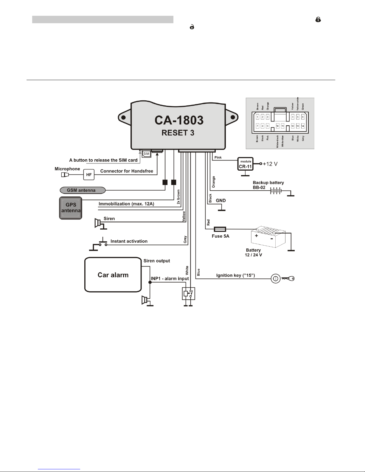
8.3 Phone calls by handsfree set (HF-03)
If the HF-03 hands free set is installed, it is possible to receive calls and
to dial pre-programmed phone numbers DIAL x. When the ignition key
is on, an RC-8x allows you to operate the hands free set. A voltage of
+12V is required on the ignition key input when a call starts or ends. The
call is done via the car alarm’s SIM, the handsfree set is not usable for
other phones.
Incoming calls – to answer them, press any button on the RC-8x
remote control. By pressing any button again, the call will be terminated.
Calls can be automatically answered, see the HF instruction manual.
Outgoing calls – when the ignition key is on (i.e. when a voltage of
+12V is present on its input), the RC-8x allows you to call up to 4 pre-
programmed numbers (see the configuration table).
If the ignition key is off (i.e. no voltage of +12V is present on its input), all
incoming calls are automatically rejected. If the car is immobilized all calls are
automatically answered (it is possible to listen in).
8.4 Alarm
When an alarm is triggered, the siren output will be switched for 30 sec.,
warning SMS messages will be sent to all phones (TEL1 to TEL4).
Subsequently, these phones will also be called by the GSM pager. If
automatic location is turned on, a request for location detection is sent.
The LED indicates the alarm for 2 minutes. To activate inputs subsequently,
an interval of at least two minutes is required.
To stop the alarm, disarm the alarm by pressing the button on the
remote control.
Example of an alarm SMS:
Your car reports: Alarm, INP activation, Time 10.12.04 01:45
9 Editing SMS texts
The SMS texts (alarm information and instructions) are factory pre-
programmed. However, it is possible to change these texts using a
mobile phone or via the www.GSMLink.cz internet page. This makes
communication convenient for the user.
To change text by mobile phone, send an SMS as below. A single SMS
enables you to specify changes to several texts. Terminate each text
with a comma:
MASTER TXT zz,text,zz,text,…
where: zz is the text index (see following table)
text is your new text – up to 30 characters, full stop (dot) or
comma cannot be used in the text, spaces are allowed
Example: MASTER TXT 03,BLOCK PLEASE
Text numbers 01 to 26 are instructions requiring a MASTER code for
their modification. If you modify these texts, you change the instructions
which the GSM pager will respond to. For example, replacing “STATUS”
with “STATE PASSWORD” will cause state detection to be only
obtainable by “STATE PASSWORD”. This way you can insert a
“password” into the texts which prevents misuse. All other texts are of
informational character and correspond to particular events, states and
input names. This allows you to adjust the names to a form which suits
you well. For example, “INP 1” can be replaced with “bonnet” etc. Texts
can be replaced using the MASTER code as well as the USER code
(optional).
A convenient way for text modification is to use the GSMLink web
page, see paragraph 11. (11)
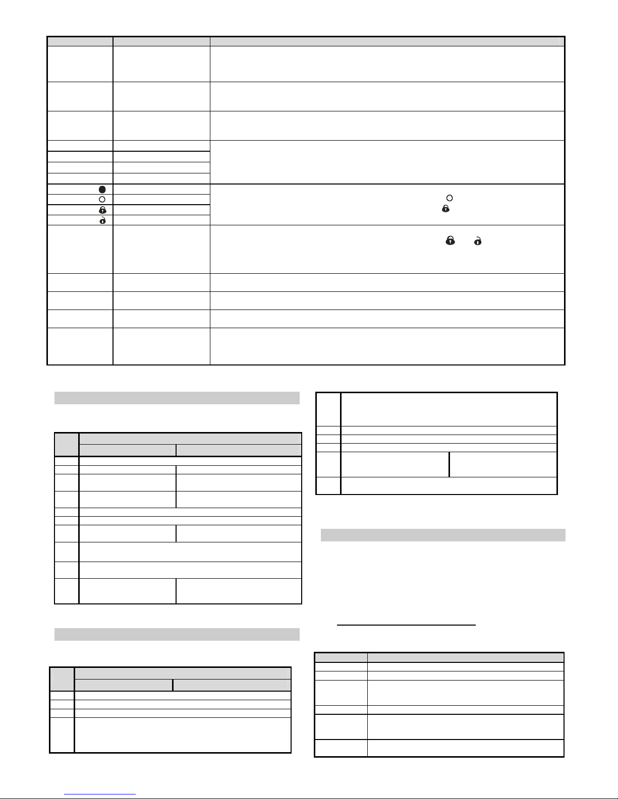
9.1 SMS text table
zz Factory default text zz Factory default text
SMS commands: 48 Telephone 4
01 AM 49 Telephone - UC
02 DM 50 Telephone - MC
03 IMO 51 Wireless detector 1
04 UNIMO 52 Wireless detector 2
05 STATUS 53 Wireless detector 3
06 HELP 54 Wireless detector 4
07 CREDIT 55 Wireless detector 5
08 DIAL 56 Wireless detector 6
09 HF 57 Wireless detector 7
10 LOCATOR 58 Wireless detector 8
11 MC 59 Wireless controller 1
12 UC 60 Wireless controller 2
13 DIP 61 Wireless controller 3
14 TEL 62 Wireless controller 4
15 LEARN 63 Vehicle in move
16 SIREN Status information:
17 SET 64 Car alarm reports
18 AUXA 65 Status:
19 AUXB 66 Armed
20 GPS 67 Disarmed
21 TIME 68 Ignition key ON
25 ON 69 Ignition key OFF
26 OFF 70 Engine is blocked
Events: 71 Engine is unblocked
30 Alarm 72 No alarm
31 Alarm cancelled by a user 73 Alarm timeout
32 Fire alarm 74 Low battery voltage
33 Tamper alarm 75 Power failure
34 Disarming 76 Power recovery
35 Arming 77 Time
36 Low battery voltage 78 Low back-up battery voltage
37 Engine is blocked 79 Partially
38 Engine is unblocked 80 Location
Source: Confirmation SMS:
40 Ignition key 81 Command accepted
41 Door contact 82 Command syntax error
42 INP1 activation 83 New MC code:
43 INP2 activation 84 New UC code:
44 Low battery voltage sensor 85 Reset
45 Telephone 1 86 Registered phone number:
46 Telephone 2 87 Credit:
47 Telephone 3 88 LEARN mode, enrolled
The grey-tinted items are not available for RESET 3 mode. Use only
ASCII character set during the text edition.
10 Functions related to GPS
An integrated GPS (Global Position System) allows the car alarm to
provide information about car location with a high precision. The location
can be obtained upon an SMS request or via the GSMLink internet web
page. A service for regularly sent location information is also available.
The car alarm is capable of recording all the car’s locations into internal
memory while the car is being used (optional).
Records can be used for statistics about car use (route listing etc.). The
information is also partially available via the GSMLink internet page.
Fully-fledged use is possible using a special service only. In that case, a
central monitoring station is required with information being automatically
downloaded. For more information, consult the manufacturer or visit the
http://www.jablotron.com/web page.
10.1 Location detection using GPS
Using a GPS instruction, you can instantly detect the car’s location. The
car alarm responds with the coordinates of the latest known location. If
the current location is not available at the time of reception of the
instruction, or if the car alarm does not change its global position for a
while, the latest location stored in internal memory is sent. Therefore,
messages are supplemented with GMT (Greenwich Mean Time). The
value corresponds to the time of detection related to the prime meridian.
In addition, information about altitude, velocity and local time of the GSM
network is provided. To monitor the car temporarily, you can use the
GPS ON instruction which makes the alarm send information about

GSM pager CA-1803BT „Athos“ 5/6 MHF56801
location after every 1km of distance moved (limited to 15 messages). In
addition, information about location can be sent automatically after an
alarm has been triggered (see the DIP switches description).
An example of an instruction sent from an authorized phone: GPS ON
An example of response: Car alarm reports: Location: (GMT:3.12.10:35)
50*43.495N;15*11.253E;515;50, Time:3.12.05 11:35
(GMT:3.12.10:35) Greenwich Mean Time (prime meridian)
50*43.495N;15*11.253E latitude and longitude
515 altitude (approximated)
50 current velocity
TimeCas:3.12.05 11:35 current local time
10.2 Time zone setting
To adjust the time information to local time, time zone setting is possible.
The car alarm adds/subtracts the time shift, expressed in hours, to the
GMT time (for middle Europe: +2 hours in summer time, +1 hour in
winter time). This instruction is only available with the MASTER code.
Instruction: MASTER TIME ±xy
xy is the time shift in hours -3,-2 …+1,+2 relative to GMT
`
MASTER TIME GSM
turns on automatic setting via incoming SMS.
10.3 Integrated Bluetooth module (BT)
A Bluetooth module is supplied as a built-in part of the CA-1803BT car alarm.
The module allows the car alarm to communicate with nearby devices
equipped with Bluetooth connectivity. For devices like PDAs, MBAs or
mobile phones, such communication can make use of navigation software
running on these devices. When disarmed and with the ignition key on, the
car alarm sends GPS coordinates via the BT which can be used for
navigation. The car alarm authorization code for device-pairing is 0000. The
ignition key must be on during the pairing process.
If the car stands still for more than 10 minutes, GPS data transmission
may start with a delay of up to 1 minute.
11 Internet remote access
The web site www.GSMLink.cz enables remote control (to users) and
setting (to installers) of the GSM pager.
To get internet access to an installed and powered car alarm you will
first be asked to register your car alarm on the first page. You will find a
unique registration code for your car alarm on the warranty card.
12 Central monitoring station communication
The GSM communicator allows central monitoring via GPRS data protocol.
The central monitoring station (CMS) gets arming, disarming and alarm
information. It also regularly checks the communication link to the car after it
is armed. So if anyone tries to tamper with GSM communications, it will
indicate an alarm at the CMS.
13 Additional features
13.1 Remote siren activation
You can operate the siren remotely by the SIREN instructions. These
instructions are accepted from all authorized (stored) phone numbers.
Commands are also accepted from any unknown phone number if they start
with the USER code.
Instruction Status
SIREN ON activates SIR output permanently
SIREN OFF deactivate SIR output
SIREN activates SIR output for 30 sec.
SIREN xxM
or
SIREN xxxS
xxM – is a numeric value of the
duration of SIR output activation, in
minutes
xxxS – as above, but in seconds.
13.2 LED indicator signals
LED state Meaning
OFF Disarmed
permanently ON Connecting to a GSM network or a phone call
Regular fast flashing Alarm or an alarm memory or learn
modePoplach, po poplachu nebo učící režim
Interrupted light Car was stopped (immobilization)
Flashing after ignition off GSM network is not available
Flashes after ignition on Number of enrolled remote controls
13.3 Pre-paid SIM card balance
It is recommended not to use prepaid cards in the car alarm. If you have
no other choice than prepaid cards, you can enable the CREDIT
instruction by the following sequence:
MASTER CREDIT uuu..u xx yyy zz
where: uuu…u is the provider’s code to obtain the balance
xx is the time period (in days) for regular checking
yyy is the threshold level below which the balance is
reported to the user (TEL1)
zz is the position of the first digit of the balance in the reply
SMS from the provider
• After this sequence has been sent once, the GSM pager will check
the balance automatically every xx days and if the balance is lower
than yyy the user will be notified (TEL1)
• If the CREDIT instruction is enabled in the above way, the user
can also obtain the current balance by the instruction CREDIT
• To disable the automatic balance checking set the time period “xx”
to 00.
13.4 Roaming
If you travel abroad and your SIM card supports roaming, the pager will
work there too except for the LOCATOR and CREDIT functions and the
GPRS data communication which will not be available.
13.5 Reset GSM
If you need to disconnect and then reconnect the GSM module to the GSM
network, then use the command “MASTER RESET GSM”.
This does not affect any settings and is typically used for GPRS activation or
charging up credit. This command always requires the Master code.
13.6 Service instruction
The DINFO instruction allows you to obtain current settings, information
about the quality of the GSM signal, the registration code for GSMLink
devices and some other parameters. This command always requires the
Master code.
Example of instruction: MASTER DINFO
Example of response: Car alarm reports: CA-1803A, SN:123456, SV:01,
LV:03, RK:ABCDE-12345-FG67, R:01, GSM:25, GPS:5, Time:3.2.06
11:35
CA-1803A car alarm version
SN:123456 identification number of the product
SV:01 software version
LV:03 language version
RK: ABCDE-12345-FG67 registration code for GSMLink
R:01 current Reset mode of the device
GSM:25 instant quality of GSM signal (ranging from 0 to 32 (best))
GPS:5 number of visible satelites (0-16)
14 AUX output
AUX output can be set to the following mode.
AUX bus – this mode allows you to connect up to four CR-11A modules
to the bus. This enables you to extend car alarm functionality via the
power output. There are two outputs available: A and B. They can be
operated by pressing two buttons together on the key fob RC-8x (see
instructions to CR-11A), or using SMS instructions. This allows you to
operate independent heating, refrigerators, flashing lights etc.). The car
must not be immobilized by use of this module, because the output
reacts to incoming SMS instructions in every state of the car alarm, in
particular, while the car is on the run, thus possibly not under the user’s
control which could cause a traffic accident.
Instruction Status
AUXA (B) Relay switches on for 1 second
AUXA ON (OFF)
AUXB ON (OFF)
ON - Switch on permanently*
OFF – Switch off permanently*
AUXA xxM in xxxS
AUXB xxM in xxxS
xxM – numeric value of requested
duration of the relay to be switched
on, in minutes
xxxS – as above, in seconds
Example of an instruction to switch B relay on for 30 seconds:
AUXB 30S
* Maximum switch-on time is 60 minutes.
* If a relay (A or B) is switched on while arming, it will be switched off. In
addition, the A relay, when switched on, will also be switched off while
disarming.
15 The back-up battery and voltage monitoring
To handle an absence of supply voltage in the car (disconnecting the
main battery, deliberate damage etc.) the car alarm is equipped with a
BB-02 backup battery. The battery supplies the car alarm when no
supply voltage is present (for 5 hours minimum). Except for the acoustic
siren, the BB-02 backs-up all the functions of the car alarm. The car

GSM pager CA-1803BT „Athos“ 6/6 MHF56801
alarm is supplied with a small current from the BB-02. Fully charging a
fully discharged battery requires 5 days. In the case of a supply voltage
outage, the BB-02 starts to generate a voltage either for the outage
duration or until it is completely discharged. While testing it or being
handled, it is possible to protect the backup battery from being
completely discharged by briefly shorting the BB-02’s terminals (the BB-
02 has to be disconnected from the power supply). This causes
disconnection of the electronics inside the back-up battery. In the case of
switch-over to BB-02 operation (after a voltage drop under 8.5V or after
complete disconnection of the battery), an SMS will be sent with
information about backup battery operation. An SMS will also be sent
after the recovery of the main power supply voltage (at least 10
minutes).
16 Emergency RESET
In the case of an emergency, when no installation MASTER code is
available, it is possible to perform an emergency RESET of the car alarm
even without the code. Such a reset causes the car alarm to be set to
factory defaults, including access codes (stated in the manual). Caution:
all pre-programmed numbers, Locator parameters, DIP and SET
parameters will be deleted. You perform an emergency reset as follows:
Turn the power supply (including back-up battery, if any) off. Pull the SIM
card out of the car alarm and insert it into a phone, enter “RESET” as a
name into the SIM card’s phone directory, and enter “0” for the
corresponding phone number. Insert the SIM card back into the car
alarm and turn the power supply on. The reset is indicated by 4 beeps.
Please contact us by phoning +420 483 559 987 or +420 606 652 997.
You can also e-mail us your suggestions to improve our services and
17 Specification
Power supply 12/24V DC (8-32V)
Stand-by consumption max. 20 mA
Max. consumption (during GSM communication) 1 A
GSM band E-GSM / GPRS 900/1800MHz
Transmitted power 2 W for GSM900, 1 W for GSM1800
Frequency 868.5MHz
Operational temperature -20°C to +70°C
Output SIR +12V (24V), max. load 1.3A
Immobilization 8A permanently, 12A intermittently
Central locking outputs max. 200mA, to GND
pulses 0.5s, 4s or 60s (optional)
Complies with ECE Regulation No. 97.00
Can be operated according to ERC/DEC98(20,21),ERC REC 70-03
Safety EN 60950
EMC EN 55022, EN 50130-4
Radio interference ETSI EN 301419-1, EN 301511,
ETSI EN 300220, ETSI EN300 328
JABLOTRON ALARMS a.s. hereby declares that the CA-1803BT is in
compliance with the essential requirements and other relevant provisions of
Directive 1999/5/EC The original of the conformity assessment can be
found at www.jablotron.com, Technical Support section
Note: Although this product does not contain any harmful materials we
suggest you return the product to the dealer or directly to the producer after
use.
97RAI-01 4532
E
8
Table of contents
Other jablotron Pager manuals