Jack Sealey sm1311 User manual

INSTRUCTIONS FOR
PLANER/THICKNESSER 200 X 120MM
MODEL NO: SM1311
Thank you for purchasing a Sealey product. Manufactured to a high standard, this product will, if used according to these instructions,
and properly maintained, give you years of trouble free performance.
IMPORTANT: PLEASE READ THESE INSTRUCTIONS CAREFULLY. NOTE THE SAFE OPERATIONAL REQUIREMENTS, WARNINGS & CAUTIONS. USE
THE PRODUCT CORRECTLY AND WITH CARE FOR THE PURPOSE FOR WHICH IT IS INTENDED. FAILURE TO DO SO MAY CAUSE DAMAGE AND/OR
PERSONAL INJURY AND WILL INVALIDATE THE WARRANTY. KEEP THESE INSTRUCTIONS SAFE FOR FUTURE USE.
1. SAFETY
1.1. ELECTRICAL SAFETY
WARNING! It is the user’s responsibility to check the following:
Check all electrical equipment and appliances to ensure that they are safe before using. Inspect power supply leads, plugs and
all electrical connections for wear and damage. Sealey recommend that an RCD (Residual Current Device) is used with all electrical
products. You may obtain an RCD by contacting your local Sealey dealer.
If the product is used in the course of business duties, it must be maintained in a safe condition and routinely PAT (Portable
Appliance Test) tested.
Electrical safety information, it is important that the following information is read and understood.
1.1.1. Ensure that the insulation on all cables and on the appliance is safe before connecting it to the power supply.
1.1.2. Regularly inspect power supply cables and plugs for wear or damage and check all connections to ensure that they are secure.
1.1.3. Important: Ensure that the voltage rating on the appliance suits the power supply to be used and that the plug is tted with the
correct fuse - see fuse rating in these instructions.
8DO NOT pull or carry the appliance by the power cable.
8DO NOT pull the plug from the socket by the cable.
8DO NOT use worn or damaged cables, plugs or connectors. Ensure that any faulty item is repaired or is
replaced immediately by a qualied electrician.
1.1.4. This product is tted with a BS1363/A 13 Amp 3 pin plug.
If the cable or plug is damaged during use, switch off the electricity supply and remove from use.
Ensure that repairs are carried out by a qualied electrician.
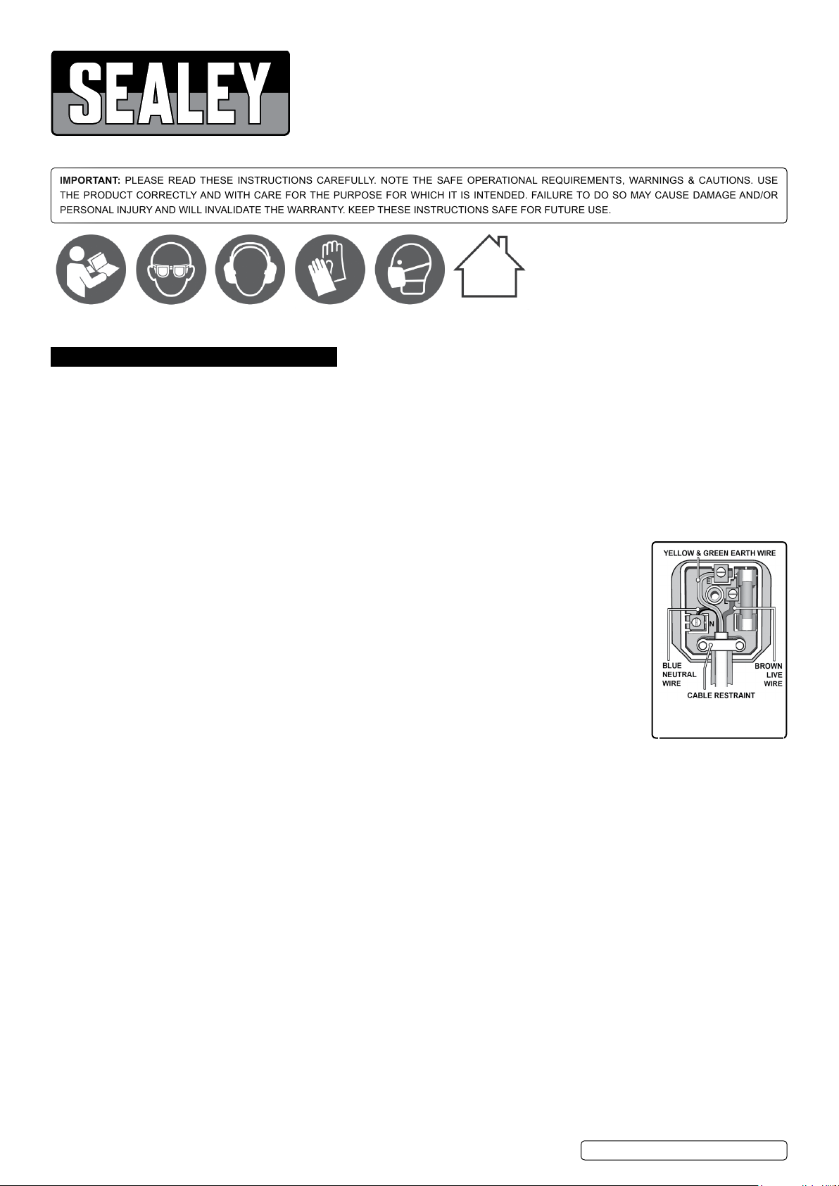
Replace a damaged plug with a BS1363/A 13 Amp 3 pin plug. If in doubt contact a qualied electrician.
a) Connect the GREEN/YELLOW earth wire to the earth terminal ‘E’.
b) Connect the BROWN live wire to the live terminal ‘L’.
c) Connect the BLUE neutral wire to the neutral terminal ‘N’.
Ensure that the cable outer sheath extends inside the cable restraint and that the restraint is tight.
Sealey recommend that repairs are carried out by a qualied electrician.
1.2. GENERAL SAFETY
WARNING! Disconnect the SM1311 from the mains power before changing accessories, servicing or performing any maintenance.
9Locate the machine in a suitable working area. Use the planer on a strong flat working surface. Keep area clean and tidy and free from
unrelated materials and ensure there is adequate lighting.
9Maintain in good condition (use an authorised service agent).
9Replace or repair damaged parts. Use genuine parts only. Unauthorised parts may be dangerous and will invalidate the warranty.
9Keep the SM1311 clean for best and safest performance and check moving parts alignment regularly.
9 Wear an approved mask and eye, gloves, ear protection.
9Handle loose blades with gloves or cloth as they are very sharp, but DO remove gloves and/or cloth before operating the SM1311.
9Keep your hands and fingers away from the blade when operating.
9Remove ill fitting clothing. Remove ties, watches, rings and other loose jewellery, and contain long hair.
9Maintain correct balance and footing. Ensure the floor is not slippery and wear non-slip shoes.
9Ensure there are no foreign objects in the workpiece i.e. nails or screws.
8DO NOT start with the workpiece touching the blade.
8DO NOT use the SM1311 for a task it is not designed to perform.
8DO NOT allow untrained persons to operate the SM1311, keep children and unauthorised persons away from the working area.
8DO NOT get the SM1311 wet or use in damp or wet locations or areas where there is condensation.
8DO NOT use SM1311 where there are flammable liquids, solids or gases such as paint solvents, waste wiping or cleaning rags etc.
8DO NOT operate if any parts are damaged or missing as this may cause failure and/or possible personal injury.
8DO NOT leave the SM1311 operating unattended.
8DO NOT operate the SM1311 when you are tired or under the influence of alcohol, drugs or intoxicating medication.
8DO NOT use without the appropriate guard in place and ensure it is correctly adjusted.
8DO NOT use blades, which are blunt as this increases the danger of kickback.
9Any portion of the cutter block not being used for planning shall be guarded.
9When planing or thicknessing short workpieces, a push-stick should be used.
SM1311 | Issue:2 (H,F) 06/02/18
Original Language Version
© Jack Sealey Limited
Refer to
instruction
manual
Wear eye
protection
Wear ear
protection
Wear
protective
gloves
Wear a mask Indoor use
only
Recommended fuse rating
13 Amp

fig.2
9Check for alignment of moving parts, binding of moving parts, mounting and any other conditions that may affect it's operation.
9If a guard or other part is damaged it should be properly repaired or replaced by an authorized service centre unless otherwise indicated
in this instruction manual.
9Stay alert - Watch what you are doing, use common sense and do not operate the tool when you are tired.
9 When not in use switch off the SM1311 and remove plug from the power supply.
NOTE! Max. allowable blade projection over cutterblock 1.0mm/0.004 inch +10%.
2. INTRODUCTION
Compact and portable power planer/thicknesser with heavy-duty cast base for accurate and smooth operation. Accurate fence tilts between 45° and 90°.
Fitted with two blades capable of handling timber up to 200mm wide. Easy conversion from planer to thicknesser. Thicknesser fitted with feed rollers. No-volt
release switch prevents uncontrolled re-start after power interruption. Includes dust extraction port.
3. SPECIFICATION
Model no: .................................................................. SM1311
Motor power: ................................................... 1250W - 230V
Max. cutting width x depth:................................... 200 x 2mm
Max. thicknesser capacity: ......................................... 120mm
Feed rate:................................................................. 7mtr/min
Cutter head speed:................................................... 8000rpm
Fence angle: .............................................................. 45°-90°
Working table size:............................................737 x 210mm
Weight:........................................................................... 29kg
4. CONTENTS
4.1. ASSEMBLY
WARNING! DO NOT plug the planer into the mains power supply until completely assembled.
4.1.1. The machine is shipped nearly complete in one carton. Additional parts which need to be fastened to machine should be located and
accounted for before assembling. (fig. 1).
A. Planer and Thicknesser
B. Angle fence
C. 4mm Hex wrench
D. Handle assembly
E. Hex bolt
F. 5mm lock washer
G. 5mm flat washer
H. Dust chute
5. INSTALLATION
5.1. The planner/thicknesser weighs 29kg. The surface it is installed on must:
- be capable of withstanding its own weight and that of any workpiece.
- be installed in a place with ample lighting and correct power supply.
- have enough room to move the workpiece through the entire cut.
- be enough room that operators or bystanders will NOT have to stand in line with the wood while using the tool.
5.2. The planner/thicknesser can be installed on a workbench using bolts, lock washers and hex nuts (not supplied).
5.3. Ensure the surface is level, does not rock and that the tables are level. Refer to g.2. for xing dimensions in millimetres.
6. OPERATIONAL SAFETY
9Regularly check that blades and lock bars are locked tight in cutterblock.
9 Max. allowable blade projection over cutterblock 1.0mm/0.004 inch +10%.
8DO NOT remove any of the machine’s safety guards other than for servicing and repair work. Keep guards operational at all times.
9Set and secure safety guards in position before operating machine.
9 When operating machine in enclosed spaces connect to a dust collector.
9 Regularly check anti-kickback ngers for proper operation.
9Always wear eye protection.
9Rebating, tenoning, moulding and recessing may not be undertaken without the use of special guards.
8DO NOT make jointing or planning cut deeper than 2 mm.
7. OPERATION
WARNING! Make sure that the switch is in off position before adjusting the cutting depth, replacing or adjusting the blades. Make sure
the blade screws are securely tightened.
7.1. SETTING ANGLE FENCE Refer to g.3.
7.1.1. Insert screw into the slot A, then locate the fence on screw D. Securely tighten screw A rst, then screw C.
7.1.2. Angle adjustment is made by means of wing screw C in accordance with scale B .
7.1.3. Angle fence (optional accessory) has to be placed into the groove of the right side plate and screwed on to the rear table by means of
the socket head screw provided.
7.2. OVERLOAD PROTECTION
7.2.1. If the overload protection activates, the motor is overloaded. The cause must be located and the fault eliminated.
7.2.2. The motor will switch off automatically and cannot be switched on again until the motor has cooled down or the power supply restored.
fig.1
SM1311 | Issue:2 (H,F) 06/02/18
Original Language Version
© Jack Sealey Limited

7.3. CHIP EXTRACTION
7.3.1. To ensure trouble free operation on enclosed premises, the machine must be connected to an extractor unit at the dust shute.
7.3.2. Dust shute connection when planing
WARNING! Disconnect power supply and turn planner/thicknesser power switch off.
7.4. DUST CHUTE CONNECTIONWHILST THICKNESSING
WARNING! Disconnect power supply and turn planner/thicknesser power switch off.
SM1311 | Issue:2 (H,F) 06/02/18
Original Language Version
© Jack Sealey Limited
fig.3
fig.4.1 fig.4.2
fig.4.3
fig.4.4 fig.4.5 fig.4.6
fig.5.1 fig.5.2 fig.5.3
Set the thicknessing working table at its
lowest position.
Insert dust chute under the working
table at an angle.
The edges of the dust chute to be in
line with the edges of the working table.
Pull the keys out from both sides of the
dust chute and locate the dust chute
with its edges in line with the edges of
the working table
Carefully insert the dust chute. Position chute so that 2 keys on
each side can be aligned with the 2
rectangular holes on the side of the
table. Ensure the keys are fully inserted
Remove the screw on the fence seat. Undo this set screw. Remove the fence assembly.

7.5. SETTING OF GUARD
7.5.1. Height adjustment is made with the lever mounted on the left side of the machine. After lifting the lock lever the blade cover can be
slide ways to set the required stock width for jointing. Push lock lever down to lock guard extrusion in position g.7.
7.6. PLANING
7.6.1. The cutting depth is set by handle L, at the front table plate N, by means of the scale for cutting depth M. Set cutting depth between
0.5 and 1.5 mm (1/64~1/16 in.). This will produce the best surface.
WARNING: The part of the cutter head not used has to be covered by the knife guard.
7.6.2. Take up a working position so that you are always on one side of the machine away from the area directly in front of or behind the
cutterhead. Place both hands on the workpiece with the ngers. DO NOT hold on to the workpiece edges. Only workpieces that rest
rmly on the machine and can be safely guided, should be planed g.8.
7.7. THICKNESSING
7.7.1. Set the desired height with handle assembly at spindle with reference to scale. 1 turn =3mm
7.7.2. Slide in narrow wood in the middle.
7.7.3. When thicknessing the table must be lubricated regularly with lubricant.
7.7.4. After having worked for a long period or when planing wet wood it may occur that the workpiece stops while pulling in.
WARNING: Switch off the machine immediately in case of failure.
8DO NOT remove chips and splinters from the tables while the machine is running.
7.7.5. Short workpieces should not be planed.
7.8. REPLACING BLADES
WARNING! Disconnect from mains power before performing any maintenance.
7.8.1. Unplug from mains and turn On/off switch off.
7.8.2. Block the blade guard from closing down.
7.8.3. Loosen and remove three blade lock screws securing blade and blade clamp.
7.8.4. Lift blade and blade clamp from cutterhead.
7.8.5. Clean any sawdust and resin buildup from cutterhead and blade clamp.
7.8.6. Place blade clamp against the replacement blade and replace in cutterhead.
7.8.7. Secure blade and blade clamp using three blade lock screws. DO NOT over-tighten blade lock screws rst.
Note: Check blade height at both ends of the blade.
7.8.8. Tighten blade lock screws.
7.8.9. Recheck blade adjustment and make sure blade is still level with outfeed table.
7.8.10. Repeat the procedure to replace the other blade.
7.8.11. Remove the scrap wood and release blade guard.
7.8.12. Make sure all the blade lock screws are tight and snug.
fig.7
SM1311 | Issue:2 (H,F) 06/02/18
Original Language Version
© Jack Sealey Limited
fig.5.4 fig.5.5 fig.5.6
fig.5.7 fig.5.8
Ret the set screw. Move the guard to the other end of the
working table.
Set the safety guard at its top position.
Fasten the set screw.
Locate the 2 keys on the dust chute to align the with the rectangular holes on both sides of the working table and insert the keys.
fig.8

SM1311 | Issue:2 (H,F) 06/02/18
Original Language Version
© Jack Sealey Limited
Sealey Group, Kempson Way, Suffolk Business Park, Bury St Edmunds, Suffolk. IP32 7AR
01284 757500 01284 703534 sales@sealey.co.uk www.sealey.co.uk
ENVIRONMENT PROTECTION
Recycle unwanted materials instead of disposing of them as waste. All tools, accessories and packaging should be sorted, taken to
a recycling centre and disposed of in a manner which is compatible with the environment. When the product becomes completely
unserviceable and requires disposal, drain any fluids (if applicable) into approved containers and dispose of the product and fluids
according to local regulations.
WEEE REGULATIONS
Dispose of this product at the end of its working life in compliance with the EU Directive on Waste Electrical and Electronic Equipment
(WEEE). When the product is no longer required, it must be disposed of in an environmentally protective way. Contact your local solid
waste authority for recycling information.
Note: It is our policy to continually improve products and as such we reserve the right to alter data, specifications and component parts without prior
notice.
Important: No Liability is accepted for incorrect use of this product.
Warranty: Guarantee is 12 months from purchase date, proof of which is required for any claim.
Note: The blades which used with the tool may be replaced or re-sharpened. Blades should not be more than 3 times by 0.05mm max.
each time.
7.8.13. The blades used in this tool can not be used to rebate.
Table of contents
Popular Planer manuals by other brands

Metabo
Metabo 602082840 Original instructions

Magnum Industrial
Magnum Industrial MI-31550 operating manual

KRAUSMANN
KRAUSMANN 9727 Operation manual

General International
General International 30-300 M1 Operating and maintenance instructions

Heinrich König
Heinrich König 161 700 manual

Makita
Makita BKP180RFJ instruction manual