Tables:
1.1.1
Table 1-1: Revision History......................................................................................................8
10.1.5 Table 1: Reader Power Settings
...............................................................................................35
10.1.6 Table 2: Gen2 Protocol Settings
...............................................................................................37
10.1.7 Table 3: General Network Settings:
..........................................................................................38
10.1.8
Table 4: Ethernet Interface Settings......................................................................................38
10.1.10
Table 5: Boot Option Settings................................................................................................40
16.1.1
Table 6: Authorized Antennas................................................................................................57
19.1.1
Table 7: Common Problems and Solutions..........................................................................59
Figures:
3.1.1 Figure 1: Assembled Development Kit and Reader
.................................................................10
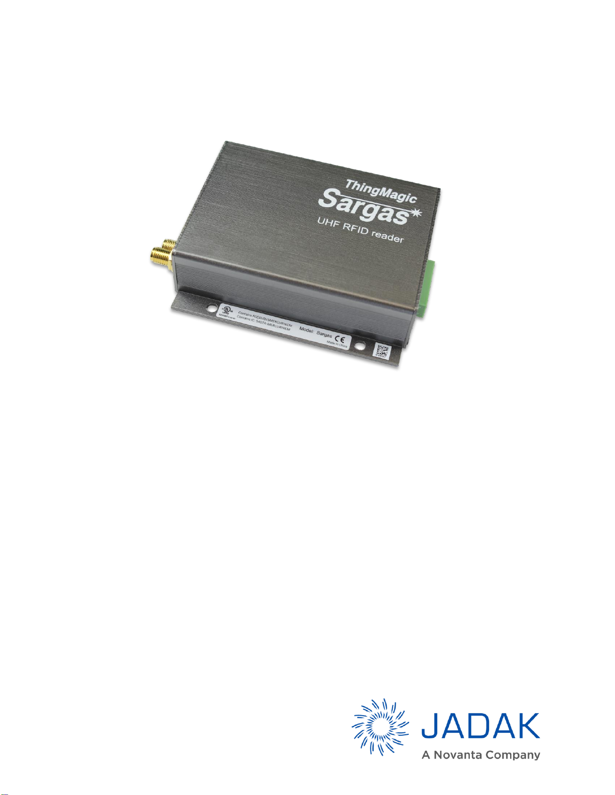
3.1.2 Figure 2: Power, LAN, and RF Connections to the Reader
......................................................10
3.1.3 Figure 3: Green Status LED (lower left)
....................................................................................11
3.1.4 Figure 4: Disabling Proxy Settings In PCʼs IP Profile
................................................................11
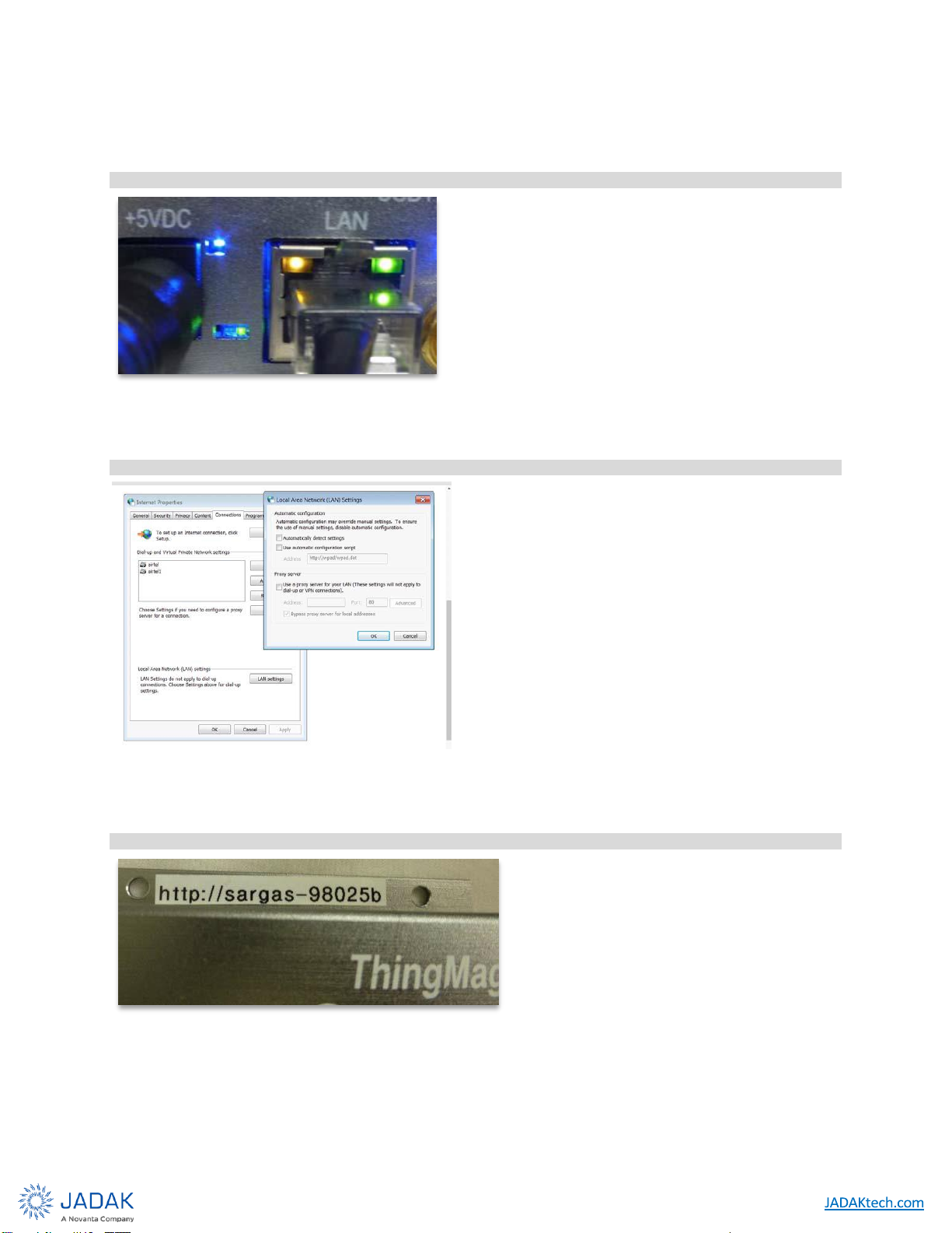
3.1.5 Figure 5: Host Name on Reader
..............................................................................................11
3.1.6 Figure 6: Entering Host Name as URL
.....................................................................................12
3.1.7 Figure 7: InitialWeb Interface Screen
......................................................................................12
3.1.8
Figure 8: Selecting the Active Antenna Port
.............................................................................12
4.1.2 Figure 9: Sargas RFID Antenna Ports
......................................................................................14
4.1.3 Figure 10: Sargas Digital and Power Connectors
.....................................................................15
6.2.1
Figure 11: Sargas Reader Interfaces
.......................................................................................18
6.2.2 Figure 12: Local Area Connection Status Window
...................................................................20
6.2.3 Figure 13: Local Area Connection Properties Window
.............................................................21
6.2.4 Figure 14: Internet Protocol TCP/IP Properties Window
..........................................................21
6.2.5 Figure 15: Typical Browser Proxy Settings
...............................................................................22
6.2.6 Figure 16: Sargas Status Page
................................................................................................23
7.2.2 Figure 17: Internet Protocol (TCP/IP) Properties Window
........................................................26
8.1.1 Figure 18: Sargas ConsoleLogin Prompt
................................................................................28
9.4.1
Figure 19: Schematic Diagram of GPIO Circuitry
.....................................................................32
10.1.2 Figure 20: Status Page
.............................................................................................................34
10.1.3 Figure 21: Settings Page
..........................................................................................................34
10.1.4 Figure 22: Reader Power, Antenna, and Protocol Settings
......................................................35
10.1.9
Figure 23: Miscellaneous Screen ..........................................................................................39
10.1.11
Figure 24: Diagnostics Page..................................................................................................40
10.1.12
Figure 25: Sargas Firmware Update Page ...........................................................................42
12.1.1
Figure 26: Typical Heat Sinks................................................................................................47
17.1.1
Figure 27: Sargas Dimension ................................................................................................58
Misc.
10.2.1
ISO-18000-6C Protocol Options............................................................................................43
10.4.1
Tag Read Meta Data..............................................................................................................44