JAGER PRO M.I.N.E. User manual

1

2
This Operations Manual contains important instructions, warnings, and
safety procedures that must be understood BEFORE assembling or
using the M.I.N.E.™ Trapping System. Failure to review and understand
the ENTIRE MANUAL prior to assembly or use could result in serious
injury or death to you or someone else.
CRUSH HAZARD: This device uses a wireless transmitter to remotely
trigger a HEAVY DROP GATE, which can cause serious injury or
death. ALWAYS secure the drop gate with the Gate Safety Clip before
conducting any work on or around the gate.
ALWAYS ensure that gate area is clear BEFORE pushing the transmitter
button, connecting wires inside the control box, or replacing the
transmitter battery.
CHILD SAFETY HAZARD: This product can cause serious injury or
death. Keep children away from equipment at all times.
At least TWO PEOPLE are required to assemble and install the
M.I.N.E.™ Trapping System. Assembly and installation without the
assistance of another person may result in injury.
ALWAYS wear appropriate protective equipment when applicable,
including eye and ear protection.
ALWAYS disconnect battery from control box when trapping system is
not in use. Reciever is constantly in use and will drain the battery.
NEVER transport M.I.N.E.™ Gate with the battery inside the control
box. Transporting the gate with battery installed will cause severe and
permanent damage to both the battery and the control box electronics.
Keep control box clean and protected from moisture in order to prevent
damage and to ensure proper operation of the trapping system.

3
Important Safety Information.....................................................................2
Equipment Inventory and Identication ....................................................4
Installation Tools and Supplies.......................................................................5
Material List of Equipment Not Included ..................................................6
Adjusting Trigger Assembly .....................................................................7
Installing Connecting Rod and Clevis ......................................................8
Installing Control Box ...............................................................................9
Attaching Connecting Rod to Latch ........................................................10
Mounting Antenna to Control Box ..........................................................11
Building the Enclosure ...........................................................................12
Installing M.I.N.E.™ Post Clips ..............................................................12
Installing M.I.N.E.™ Gate .......................................................................13
Installing 18-60™ Panels and Posts ......................................................14
Installing 18-60™ Rigid Panels................................................................16
Installing T-Post Camera Mount .............................................................17
Mounting Booster Antenna .....................................................................18
Testing Gate Operation ..........................................................................19
Feeder Modications ..............................................................................20
Replacing Long Range Transmitter Battery ...........................................21
Warranty .................................................................................................22

4
Gate with Frame Trigger Assembly Control Box
Receiver Self Tapping Screws Connecting Rod & Clevis
Rod Adapter Long Range Transmitter 12 volt Battery
Safety Pin Antenna Tube

5
Drill 20’ Tape Measure Hand Pick T-Post Driver
Mini Bolt Cutter 3/8” Nut Driver 1/2” Socket
with Wrench
9/16” Wrench
Pliers Screwdriver 3/32” Allen Wrench Multi-meter
11 Gauge Steel
Galvanized Wire
8” Zip Ties Shovel T-Post Puller

6
Items available for purchase from JAGER PRO™ authorized distributors
16 ft. 18-60™ Flex Panels (6 ea)
M.I.N.E.™ Camera7ft. T-Posts (24 ea)
M.I.N.E.™ Post Clips M.I.N.E.™ Clip Socket
Booster AntennaI.C.E.™ Camera
Booster Antenna Pole T-Post Camera Mount 6v Battery Box
Feeder with Dinnerbell
and Digital Timer
8 ft. 18-60™ Rigid Panels (12 ea)

7
Adjust the trigger assembly left or right
until the trigger square stock is sitting on
the outside edge of the trip arm. Then
tighten the trigger assembly nuts with a
9/16” wrench.
Lightly tighten the bolt and nut on the
trip arm using a 1/2” wrench and socket
so the trip arm stays in the “up” position
without falling, but can still easily move.
Work the trip arm up and down onto the
latch to ensure there is no binding.
It is important the trip
arm stays in the “up” position without
falling. This step allows the use of both
hands to raise the gate.
Loosen the trigger assembly nuts with a
9/16” wrench.
The trigger is set at the factory and should not require
adjustment. However, follow these steps if the trigger needs adjustment.
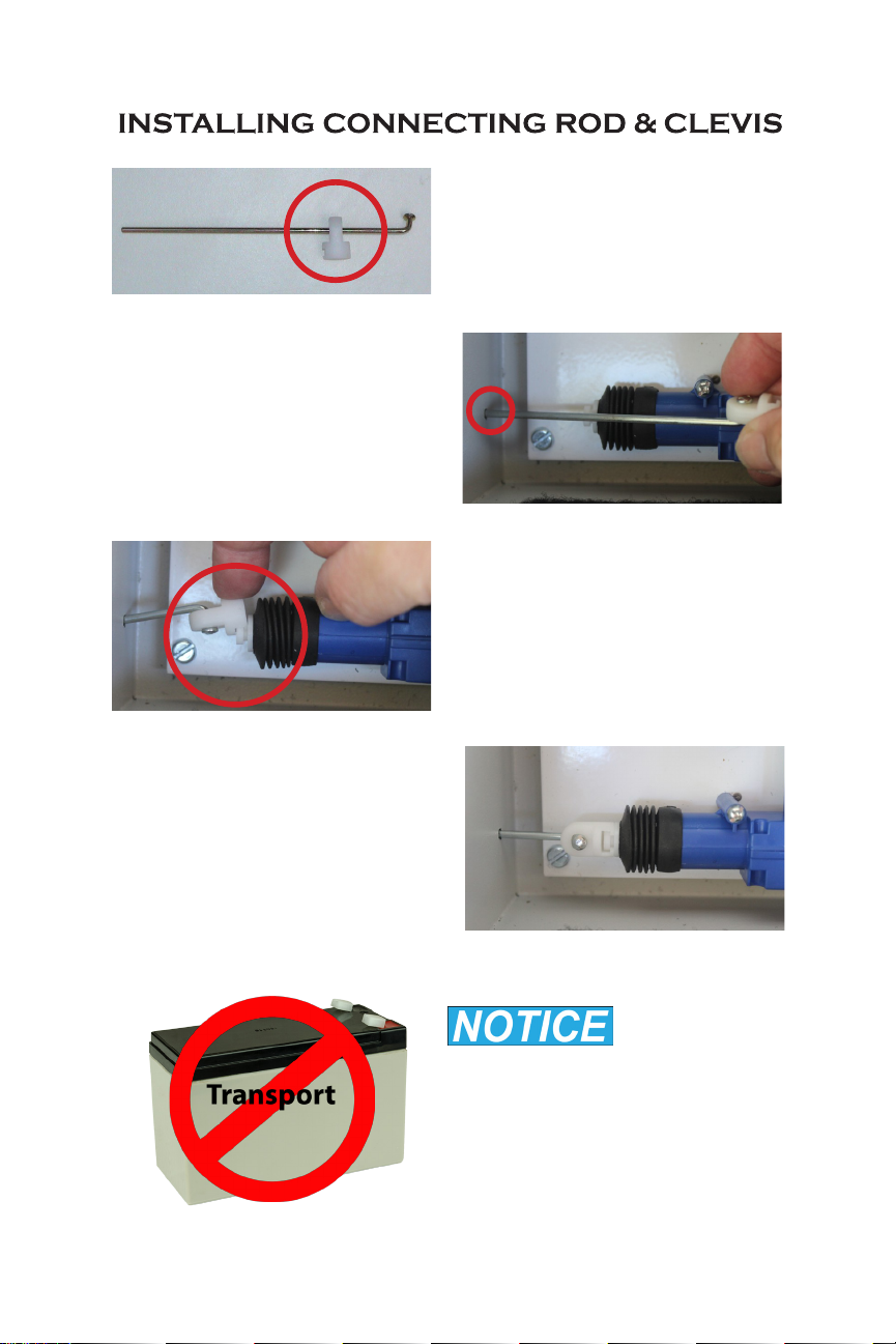
8
Rotate the connecting rod and
clevis to this position. Work the
rod back & forth to ensure there is
no binding.
Never transport
the M.I.N.E.™ Gate with battery
inside the control box or severe
damage to electronics and battery
will occur. Remove battery during
transport and always disconnect
when not in use.
Push the 1/8” connecting rod
through the plastic clevis.
Slide the connecting rod through
the actuator hole inside the control
box.
Align the slots and gently snap
the clevis onto the actuator arm.

9
Place the control box onto the frame in
this position.
Secure the rod adapter with pliers. Turn
the set screw with a 3/32 Allen wrench to
break the Loctite®seal at threads.
Place the rod adapter through the
latch arm. Guide the connecting rod
through the rod adapter while sliding the
control box into place. See “Attaching
Connecting Rod to Latch” on next page
before tightening rod adapter.
Ensure the control box is tight against the
trigger assembly. Using a 3/8” nut driver
and drill, secure the control box to the
frame with four #14 self tapping, 3/4” long
screws.

10
Notice the actuator arm has more than one inch of travel. The actuator
arm and connecting rod is shown below fully “IN” and fully “OUT”.
Do not secure the rod to the latch with the connecting arm all the way
out or it will hit the bracket on the latch assembly when triggered. The
illustrations below show the proper setting on the right side of the
bracket. Using a 3/32 Allen wrench, turn the set screw inside the rod
adapter to secure the connecting rod to the latch.
Erect feeder and secure each leg with
a T-post and 11 gauge galvanized steel
wire. Following the steps of our “Capture
Success Matrix”, build an enclosure only
after the hogs trust the area as a food
source for multiple days in succession.
Other manuals for M.I.N.E.
4
Popular Security System manuals by other brands


EDM
EDM Solution 6+6 Wireless-AE installation manual

Highway Safety Group
Highway Safety Group EA401 user manual

Siren
Siren LED GSM operating manual

Detection Systems
Detection Systems 7090i Installation and programming manual

Se-Kure Controls
Se-Kure Controls MicroMini SK-4841 instructions

Siemens
Siemens FDM273 manual