JAKA MiniCab Instructions for use

JAKA Robotics
Hardware User Manual
JAKA MiniCab
Original Instructions (en)
File Version: 1.2
Robot: Zu series, Pro series

II
Notice:
The definition of collaborative robots follows the ISO standards and relevant national standards to protect the
safety of operators. We do not recommend applying the robots directly to cases when the operating object is a
human. However, if there is a need for the robot to operate on a human, the robot needs to be equipped with a
safe, reliable, fully tested and certified safety protection system to protect the human, provided that the
personnel safety is fully assessed by the user or application developer.
The manual is the exclusive property of the JAKA Robotics Ltd. (hereinafter referred to as the “JAKA”) and
JAKA fully reserves its copyright and interpretation right. This manual and parts thereof must not be reproduced
or copied without JAKA’s written permission.
We will regularly revise the manual, and the content may be updated without notice. Please check the factual
product information carefully before reading this manual.
This manual is applicable to all products and/or services manufactured or provided by JAKA (hereinafter
referred to as the “products"). The information contained in the manual is provided "as is" and is subject to the
local laws. To the maximum extent permitted by law, this manual does not constitute any form of express or
implied representation or warranty of JAKA, neither constitute a guarantee of merchantability, suitability for
specific purposes, achievement of expected results, or non infringement of the products. JAKA assumes no
responsibility for any error or omission that may appear in this manual, or any accident or indirect injury arising
from the use of this manual and the products described therein. Before installing and operating the product,
read this manual carefully.
The pictures in this manual are for reference only.
If the robot body is transformed or disassembled, JAKA will not be responsible for after-sales services. JAKA
reminds users that they must use safety equipment when using and maintaining JAKA robots and must comply
with the safety terms.
Programmers of JAKA robots and designers and debugging personnel of robot systems must be familiar with
the way to program JAKA robots and install system applications.
Manual Instruction
This manual mainly includes precautions for safe use of robot controller, mechanical and electrical interfaces,
installation and maintenance.
Users of this manual shall have received basic mechanical and electrical training, which will be more helpful to
the installation and use of the robot.
More Information
For more information about our products, please scan the QR code on the
right to visit our official website: www.jakarobotics.com.

III
Contents
Chapter 1 Safety Specification...............................................................................................................7
1.1 Introduction .....................................................................................................................................7
1.2 Safety Warning Signs Description ..................................................................................................7
1.3 Safety Precautions ..........................................................................................................................7
1.4 Responsibility and Risk ...................................................................................................................8
1.5 Emergency ......................................................................................................................................9
1.6 Precautions for Transportation and Handling .................................................................................9
Chapter 2 Quick Start............................................................................................................................10
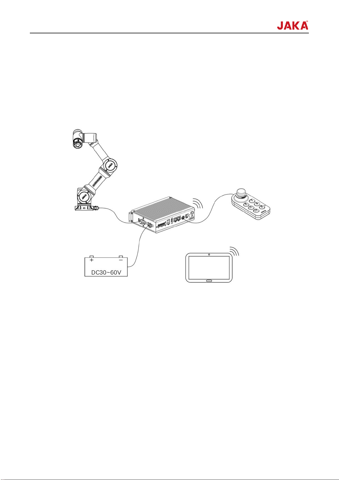
2.1 Typical Application Schematic Diagram........................................................................................10
2.2 Composite Robot Application........................................................................................................10
2.3 Operation Terminal........................................................................................................................11
2.4 Controller and Control Stick ..........................................................................................................11
Chapter 3 Mechanical Specification ....................................................................................................14
3.1 Outline Dimension.........................................................................................................................14
3.2 Specification..................................................................................................................................15
3.3 Installation .....................................................................................................................................15
3.2.1 Installation Method.................................................................................................................15
3.2.2 Installation Environment Requirements.................................................................................17
Chapter 4 Electrical Specification .......................................................................................................18
4.1 Introduction ...................................................................................................................................18
4.2 Absolute Limit Parameter..............................................................................................................18
4.3 Recommended Operating Conditions...........................................................................................18
4.4 Typical Power Consumption .........................................................................................................19
4.5 Computer Configuration................................................................................................................19
Chapter 5 Definition of Interface..........................................................................................................20
5.1 Front Panel Interface ....................................................................................................................20
5.1.1 Integrated Interface (I/O) .......................................................................................................20
5.1.2 Control stick Interface (STICK)..............................................................................................22
5.1.3 Emergency Stop Interface (E-STOP) ....................................................................................22
5.2 Side-panel Interface ......................................................................................................................23
5.2.1 Power Interface......................................................................................................................23
5.2.2 Robot Interface ......................................................................................................................24
Chapter 6 Detailed Introduction...........................................................................................................25
6.1 Overview .......................................................................................................................................25

IV
6.2 Function Application......................................................................................................................25
6.2.1 Electrical Service Requirements............................................................................................25
6.2.2 Emergency Stop ....................................................................................................................26
6.2.3 Switch-ON/OFF .....................................................................................................................26
6.2.4 LED State Indicator................................................................................................................28
6.2.5 Integrated UDIO.....................................................................................................................28
6.3 Braking Voltage Setting.................................................................................................................29
6.4 Network Settings ...........................................................................................................................30
6.4.1 Introduction to Network Interface...........................................................................................30
6.4.2 Wi-Fi.......................................................................................................................................30
6.4.3 Network Configuration ...........................................................................................................30
Chapter 7 Maintenance and Repair .....................................................................................................32
7.1 Safety Instructions ........................................................................................................................32
7.2 Recommended Inspection Activities .............................................................................................32
7.2.1 Preventive inspection activities..............................................................................................33
7.3 Replacement and Preservation of Components ...........................................................................33
7.3.1 Preservation of Components.................................................................................................34
Chapter 8 Warranties ............................................................................................................................36
8.1 Product Warranty ..........................................................................................................................36
8.2 Disclaimer .....................................................................................................................................36

File Version: 1.2 5 / 37 JAKA MiniCab Hardware User Manual
Preface
JAKA MiniCab is a new compact robot controller that can be used with the JAKA Zu series and JAKA Pro
series of collaborative robots.
JAKA robotics uses the control mode of mobile intelligent terminal and APP to connect with the robot. And one
mobile terminal can control several robots. Operators do not need to master professional programming
language and can easily complete the programming by manually controlling the robot. In this way, the
man-machine collaboration can be more leisurely, which greatly improves the production efficiency.
MiniCab is a compact robot controller based on wide voltage DC power supply. It can be seamlessly integrated
into the existing infrastructure and can provide powerful performance for more application scenarios. With
Wi-Fi hotspot, it can be widely used in AGV, composite robot and other mobile platforms, and support intensive
deployment.

File Version: 1.2 6 / 37 JAKA MiniCab Hardware User Manual
Product List
When you purchase a JAKA MiniCab robot controller separately, the product you receive is as follows:
Name
Quantity
JAKA MiniCab
1
Control stick
1
Power supply, emergency stop, IO terminals
3
Wi-Fi antennas
1
Brackets and matching screws
2
Guide rail installation assembly (Optional)
1

File Version: 1.2 7 / 37 JAKA MiniCab Hardware User Manual
Chapter 1Safety Specification
1.1 Introduction
This chapter mainly introduces the safety principles and specifications that shall be observed when using
robots or robot systems. Users shall carefully read the safety related contents in this manual and strictly follow
them. Operators shall be fully aware of the complexity and danger of the robot system and pay special attention
to the contents related to warning signs.
1.2 Safety Warning Signs Description
The following warning signs are used to describe the hazard levels stipulated in this manual. Please strictly
observe the safety contents.
Warning:
This sign indicates a potentially dangerous use of electricity, which, if
not avoided, can cause personal injury or serious damage to the
equipment.
Warning:
This sign indicates a potentially dangerous situation, which, if not
avoided, can cause personal injury or serious damage to the
equipment.
Warning:
This sign indicates a hot surface that may cause danger. If touched, it
may cause personal injury.
1.3 Safety Precautions
This chapter is intended to protect the operator and point out the related matters that need to be paid attention
to during the first installation. Users need to read the safety warnings in this manual carefully, but there are still
many possibilities, and many descriptions of them cannot be exhaustive. We have described various situations
as much as possible.
1. Professional personnel are required to install and commissioning
the MiniCab and the robot in accordance with the specifications.
2. The setting and modification of robot parameters shall be carried
out by authorized personnel and unauthorized personnel shall be
prevented from changing parameters.
3. If the operator uses his/her own controller, he/she shall bear the
risks.

File Version: 1.2 8 / 37 JAKA MiniCab Hardware User Manual
1. Do not connect safety devices to a normal I/O interface to avoid
injury.
2. Make sure that the correct installation settings (such as the robot
installation angle, mass in TCP, the TCP offset, the security-related
configuration) are performed, and the installation file is saved and
loaded into the program.
3. Tools and obstacles shall not have sharp corners or points. Make
sure all personnel are out of reach of robots.
4. Connecting different machines may aggravate the danger or
introduce new risks. A comprehensive risk assessment shall be
conducted throughout the installation at all times.
5. The controller uses DC voltage input. Please use the DC power
supply in a standard way. When using battery power, you need to
consider the related risks brought by the battery.
6. For the precautions of the robot, please refer to the specific model.
1. The robot and MiniCab will generate heat when they are working.
Do not touch the robot when it just stops and you can only touch it
after the power is off for about 1 hour.
2. MiniCab will generate heat and do not put your hand on the shell of
MiniCab.
1.4 Responsibility and Risk
Liability
This manual does not cover all applications of how to design, install and operate a robot, nor does it cover all
peripherals that may affect the safety of the robot system.
The integrator of JAKA bears the liability to ensure that the applicable laws and regulations of the relevant
country are followed to ensure that there is no significant risk in the complete robot application.
All safety information contained in this manual shall not be construed as a guarantee of JAKA, and injury or
damage caused by an operator may occur even if all safety instructions are complied with.
The JAKA product will consider the safety design and be adapted to the operation handle and the user
emergency stop interface for the safe operation in case of an emergency. Please use it in accordance with the
product requirements. The company will not be liable for the safety problems caused by the unauthorized
disassembly and modification of the emergency stop interface.
JAKA will keep improving the performance and reliability of our robots. We are not responsible for errors or
omissions in this manual and reserve the right of final interpretation of this manual.
Risk
When there is interaction between operators and the robot, there is inevitably direct or indirect physical contact.
When touching the robot, users must have sufficient awareness of self-protection. Users need to be cautious
when using the robots. Some possible hazards are as follows:
The robot drops and cause any injury when it is moved;
The fastening screws of the robot get loose and cause any injury;
During the operation, the robot pinches your fingers or collide with you;
The robot causes any injury due to lack of prompt repair of faults;
Potential danger when sharp-end actuators or sharp tool coupling ends are used;
Potential injury when the robot is operated in toxic or corrosive environments.
Use it in strong magnetic environment.

File Version: 1.2 9 / 37 JAKA MiniCab Hardware User Manual
1.5 Emergency
When an emergency occurs, press the E-STOP button to immediately stop all movements of the robot.
Emergency shutdowns shall not be used as a risk mitigation measure but may be considered as a secondary
protection.
1.6 Precautions for Transportation and Handling
The robot/controller needs to be fixed in its original packaging during transportation to ensure that the
equipment is stable and kept dry.
When the robot is hoisted, corresponding measures shall be taken to locate the robot to avoid damage caused
by accidental movement.
When moving the robot from its packaging to the mounting position, hold the robot until all the bolts on the base
of the robot are fastened.
Warning:
1. Make sure your back or other parts of your body are not overloaded when you are lifting the device. Use
suitable lifting equipment. JAKA is not liable for the damage caused during the transportation of the equipment.
2. Ensure that installation instructions are strictly followed during robot installation.

File Version: 1.2 10 / 37 JAKA MiniCab Hardware User Manual
Chapter 2Quick Start
Before reading this chapter, make sure that you have read and fully understood the Safety Specifications in
Chapter 1.
This chapter will provide a quick introduction to JAKA MiniCab's basic components and usage as a preliminary
understanding of the robot. For detailed mechanical and electrical specifications, please refer to other
chapters.
2.1 Typical Application Schematic Diagram
Figure 2-1 Typical MiniCab Application
As shown in Figure 2-1, the JAKA MiniCab adopts the mode of wireless interconnection and integrates the
function of Wi-Fi hotspot internally. It needs to include the following parts when in use:
Operation Terminal: The device for users to perform programming, setting, and other operations.
Robot arm: Main moving parts to achieve the desired action of the user. At the same time, the robot is
equipped with a ring indicator light indicating the status of the robot, buttons for dragging and programming,
and an I/O interface for connecting tools, namely the TIO interface.
Control stick: is equipped with user-friendly handle to control robot operation and emergency stop operation.
DC Power: The controller adopts DC voltage input, supports 30-60VDC wide voltage range, and can use 48V
battery or DC module power supply as input source.
2.2 Composite Robot Application

File Version: 1.2 11 / 37 JAKA MiniCab Hardware User Manual
Figure 2-2 Typical Application Diagram of Composite Robot
As shown in Figure 2-2, the JAKA MiniCab can be used with mobile platforms such as AGV, and the 48V
power battery inside the AGV can be used to provide power, which is compact in size with an easy and simple
integration.
2.3 Operation Terminal
JAKA provides JAKA Zu APP developed based on Android system, and the minimum operation hardware
configuration of this software is shown in Table 2-1:
Table 2-1 Operation Terminal Configuration Table
Terminal type
Pad
Computer
Operating system
Android 10.0 and above
Windows 7 32/64 bit and above
CPU
Snapdragon 835 and comparable
processors
intel CORE i3-6100 3.7GHz and
above
Video card
/
intel HD Graphics 530 and above
Storage
512MB available
1GB available
System memory
4GB
8GB
Network
communication
Wi-Fi
Wi-Fi or Ethernet
When purchasing JAKA Zu/Pro series collaborative robots, users can also request to purchase operation
terminals or use their own pad.
2.4 Controller and Control Stick
The controller provides a keypad handle that can be used to start the robot without using the APP when the
running program is written and loaded by default.
The handle sends control commands to the controller through the combination of keys. The function of the
combination of keys is described as follows:

File Version: 1.2 12 / 37 JAKA MiniCab Hardware User Manual
Table 2-2 Handle Function Description
1
Emergency
stop button
For emergency stop
Note: The emergency stop button is limited to emergencies and should not be
used as regular power-off equipment.
2
Power on/off
button
Power on: Press the power button for 1s and release. The buzzer beeps, and the
controller is switched on.
Power off: Hold down the power button for 3s or more. The control stick beeps
6-7 times, and the controller is switched off.
3
Enable button
Robot power-on: When the robot is powered off, press the enabled button,
waiting for the indicator of flange to turn blue, which means the robot is powered
on.
Robot power-off: When the robot is powered on, waiting for the indicator of flange
to go off, which means the robot is powered off.
Enable robot: When the robot is powered on, press and hold the lock button, and
then press the enable button at the same time until the indicator of flange to turn
green, which means the robot is enabled.
Disable robot: When the robot is enabled, press and hold the lock button, and
then press the enable button at the same time until the indicator of flange to turn
blue, which means the robot is disabled.
4
Start/Stop
button
Start the program: Press the button to start the default program, operate the
robot until it reaches the initial position of the program, and then execute the
default program.
Stop the program: Press the button to terminate the program when the robot runs
the program.
5
Reset button
Reset: After the robot is enabled, press and hold the reset button during the
process of the non-operation program to control the robot to return to safety
orientation set by the JAKA Zu APP. When the program runs to the default
position, press and hold the button, and the lock indicator is blue.
6
Pause/Resume
button
Pause: During the automatic operation of the robot, press the button to pause
program execution.
Resume: Press the button to resume program execution when the robot
movement is paused

File Version: 1.2 13 / 37 JAKA MiniCab Hardware User Manual
7
Lock button
Lock the control stick: Hold down the lock button for 3s, and the lock indicator is
orange.
Unlock the control stick: Hold down the lock button for 3s, and the lock indicator
goes out.
Combination function: Other buttons can be used with the lock button.
8
Lock indicator
Lock state: In the lock state, the indicator is orange, and all buttons except the lock
button and power button are disabled. The APP can control the robot.
Unlock state: In the unlock state, the lights go out, and the control stick can be
used. The APP interface is gray, and you cannot use the APP to control the robot.
9
Control stick
indicator
During the controller power-on process, the control stick indicator first flashes red,
blue and green alternately with three beeps, and then it turns orange, waiting for
the controller to start. The control stick indicator flashes blue when the controller
program is running normally. After the robot is enabled, the control stick light
flashes green.
Note:
Once the controller is powered on, the control stick will beep twice per second if any button is pressed.
When using the control stick to operate the robot, ensure that the robot you are operating is within your sight
and follow the relevant safety guidelines to avoid any harm to personnel or equipment near the robot.

File Version: 1.2 14 / 37 JAKA MiniCab Hardware User Manual
Chapter 3Mechanical Specification
MiniCab is compact in design, featured with small size and high integration. It is mainly used in conjunction with
the JAKA products and peripheral accessories.
Figure 3-1 Product Appearance Rendering
3.1 Outline Dimension
The dimensions of JAKA MiniCab are shown in Figure 3-2. Standard accessories include brackets, which
support panel mounting and base mounting. At the same time, if the guide rail installation is needed, the rail
installation component is optional.
Figure 3-2 Outline Dimensions and Installation Hole Bitmap

File Version: 1.2 15 / 37 JAKA MiniCab Hardware User Manual
3.2 Specification
Weight
1.1kg (2.43lb)
Dimensions (W × H × D)
180×46.6×128mm (7.09×1.84×5.04in)
Ambient Temperature
0-50°C (32-122°F)
Protective class
IP20
Materials
Aluminum alloy steel
Power
30~60VDC
Communication Ways
TCP/IP. Modbus TCP. Modbus RTU
I/O Port
7 segment I/O multiplexing
I/O Power Supply
24VDC
3.3 Installation
3.2.1 Installation Method
MiniCab shall be installed reliably before use. Here are three ways to install:
3.2.1.1 Bracket Mounting
Figure 3-3 Rear Lug Mounting Diagram
The upper and lower brackets are factory default configuration, and the installation method is shown in Figure
3-3. 4 M3 screws shall be selected for fixing parts, and the dimention of mounting holes is shown in Figure 3-2.
When the fixed plate is a moving platform, in order to reduce the impact of moving vibration on MiniCab, it is
recommended to add a rubber washer between the MiniCab and the fixed plate.

File Version: 1.2 16 / 37 JAKA MiniCab Hardware User Manual
3.2.1.2 Base Installation
Figure 3-4 Base Installation Schematic Diagram
MiniCab supports the bottom mounting and fixing mode, as shown in Figure 3-4. 4 M3 screws are selected for
fixing, and the dimention of the bottom mounting hole are shown in Figure 3-2. When the fixed plate is a moving
platform, in order to reduce the impact of moving vibration on MiniCab, it is recommended to add a rubber
washer between the MiniCab and the fixed plate.
3.2.1.3 Rear guide rail Installation
Figure 3-5 Rear rail Installation Diagram
MiniCab also supports rear installation of national standard guide rail, and the guide rail buckle is optional.
When there is a need for rear guide rail installation, please contact JAKA technical service personnel to
prepare before shipping or arrange a redelivery.

File Version: 1.2 17 / 37 JAKA MiniCab Hardware User Manual
3.2.2 Installation Environment Requirements
MiniCab needs to be installed in a dry place with good ventilation and cooled by natural convection; when
there is a large amount of heat generated in the use scenarios, such as high-speed running, heavy load or
frequent braking, an external fan is required to cool the MiniCab. In order to ensure the MiniCab can be cooled
by a fan and natural convection, please refer to Figure 3-6 for installation, and reserve a distance of more than
100mm(3.94in) between each MiniCab (heat dissipation requirement), and reserve a distance of more than
50mm(1.97in) on both sides of the longitudinal direction.
Figure 3-6 Installation with Space Reserved
Note:
⚫Do not install in damp or water spattering environment;
⚫Do not use the equipment in the enclosed environment, which will cause high temperature, shorten
service life and even damage the equipment;
⚫Keep away from heat sources such as stoves;
⚫Do not use the product near corrosive and flammable gases, combustibles, such as hydrogen sulfide,
chlorine, ammonia, sulfur, chlorinated gases, acids, bases, salts, etc.;
⚫This product is used at altitudes below 1000m(3280ft), and please de-rate if the altitude is above
1000m(3280ft).

File Version: 1.2 18 / 37 JAKA MiniCab Hardware User Manual
Chapter 4Electrical Specification
4.1 Introduction
This chapter mainly describes the absolute limit parameters of MiniCab and the recommended conditions of
use. When using the robot and MiniCab, users shall follow the recommended electric parameters, and reaching
or exceeding the limit parameters may cause damage to the controller hardware.
4.2 Absolute Limit Parameter
Table 4-1 Electric Limit Parameters
Minimum value
Maximum value (1) (2)
Unit
VL+
Logic power supply voltage
-0.3
70
V
VP+
Power supply voltage
-0.3
70
V
VUDIO_COM+
Integration interface common terminal
voltage
-0.3
30
V
IUDIO_24V
Integration interface output current
0
2.7
A
IUDIOx
Integration interface single channel output
current
0
2
A
VbusRS485
RS485 bus withstand voltage
-70
70
V
Note:
(1) Exceeding the values listed in the "Absolute Limit Parameters" may cause permanent damage to the
equipment. These represent limits and it is not recommended that the functional operation of the device be
performed under these conditions or any other conditions other than the "Recommended Conditions".
(2) All voltage values except bus voltage are related to the grounding.
4.3 Recommended Operating Conditions
Table 4-2 Recommended Operating Conditions
Minimum value
Typical value
Maximum value
Unit
VL+
Logic power supply voltage
18(1)
48
60
V
VP+
Power supply voltage
32(2)
48
58
V
IRMS
Average operating current
20
A
Ipeak
Output peak voltage
40
60(3)
A
IUDIOx
User interface single channel
output current
1
A
Ambient Temperature
0(32)
50(122)(4)
°C (°F)
Atmospheric
1
Bar

File Version: 1.2 19 / 37 JAKA MiniCab Hardware User Manual
Altitude
1000(3280)
m(ft)
Relative humidity
10
90
%RH
Note:
(1) The minimum logic voltage can enable the logic functions related to the controller, but the output value of
UDIO_24V depends on the logic supply voltage.
(2) The power supply mainly provides power to the robot. Generally, the robot will be protected when voltage is
less than or equal to 30V. Therefore, the anomaly caused by voltage loss and drop shall be considered when
the minimum value is input.
(3) The peak value of the output current is related to the model and working status of the adapted robot.
Derating is recommended when the MiniCab is used with Zu 12 and Zu 18.
(4) The surface of the controller is hot during operation, which is required to be used in well-ventilated and
heat-dissipating conditions.
4.4 Typical Power Consumption
Test condition: 25°C, 48V logic voltage, 48V robot power supply, robot and integrated interface not connected,
control stick connected.
Table 4-3 Typical Power Consumption
Parameter
Test operation
conditions
Minimum value
Typical value
Maximum value
Unit
Shutdown
consumption
0
W
Power on
11
14
W
Power on the robot
25
33
W
4.5 Computer Configuration
Table 4-4 Computer Configuration
CPU
The main frequency is 2GHz and the Turo frequency is 2.4GHz
RAM
DDR3L 2G
Hard drives
32GB (with larger memory options)
Computer interface
HDMI. USB3.0 x1. USB2.0 x1. Ethernet x2

File Version: 1.2 20 / 37 JAKA MiniCab Hardware User Manual
Chapter 5Definition of Interface
MiniCab has user interfaces on the front panel and side panel. The front panel includes 20PIN integrated I/O,
USB, HDMI, LAN, control stick and E-STOP interface, Wi-Fi status indicator and power button.
The side panel includes a power input interface, a robot connection cable interface, 2.4G Wi-Fi antenna, and
an internal integrated router reset button.
Table 5-1 Interface Definition Description
Interface Name
Quantity
Description
UDIO
7
7-channel digital interface, NPN type I/O can be configured
RS485
2
Master and Slave
USB
2
USB3.0*1. USB2.0*1
HDMI
1
Used for external display devices
LAN1
1
Internally integrated router interface, 100 MB Ethernet interface
LAN2
1
10M/100M/1000M adaptive Ethernet interface
DC_INPUT
1
Logic & power DC power input interface
COBOT
2
Robot power supply and CAN communication interface
5.1 Front Panel Interface
Figure 5-1 Diagram of Front Panel
5.1.1 Integrated Interface (I/O)
Figure 5-2 Diagram of Integration Interface
1357911 13 15 17 19
246810 12 14 16 18 20
Table of contents
Popular Network Hardware manuals by other brands

Keysight
Keysight ixia BreakingPoint 20 installation guide

ZyXEL Communications
ZyXEL Communications VMG4005-B50B Overview guide

Avalue Technology
Avalue Technology EPC-BYT2 Quick installation guide

Moxa Technologies
Moxa Technologies AWK-3252A Series Quick installation guide

XAG
XAG WM101 instruction manual

Siemens
Siemens SIMATIC NET CP 1515 manual