Null Mode Locating
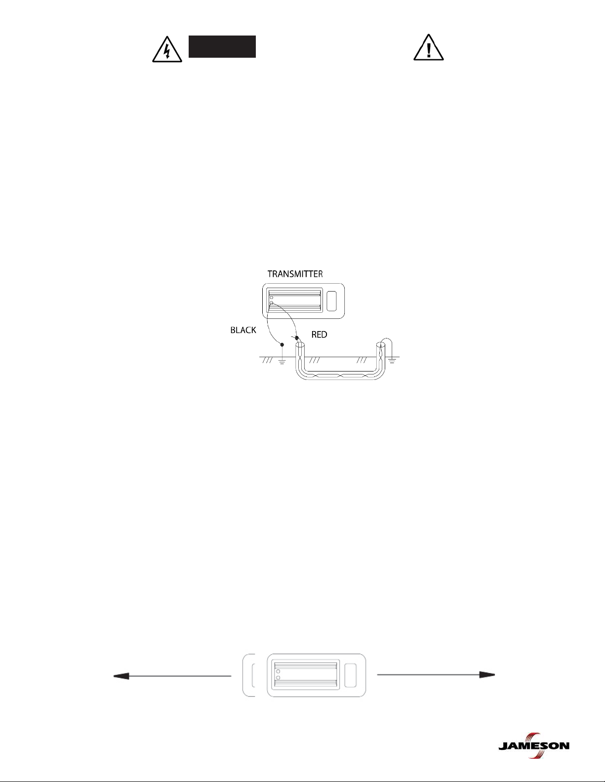
Move Receiver left to right across cable path. When Receiver is directly above cable or pipe, a
Null (lowest meter reading and lowest audio tone) will occur. When moving Receiver left or right
of Null point, meter reading will rise to a maximum point (Peak). The audio tone will also be at its
highest pitch. When Receiver is moved beyond Peak, meter reading will begin to fade.
Trace path by walking away from Transmitter at a moderate pace. Move Receiver to the left and right when
walking, following Null indications.
As you trace path, Peak meter reading may slowly fade as you move away from the Transmitter. Press and
release Gain buttons as needed to compensate for changes in signal level. If Peak meter readings suddenly
changes in level (higher or lower), one of the following may have occurred:
a) Junction where the signal divides and goes several directions.
b) Break in the cable or shield.
c) Change in the depth of the cable or pipe.
d) Insulated pipe fitting.
e) Slack loop of cable.
If you can no longer trace path, even with Gain control set to maximum, connect Transmitter to far end of path
and begin tracing path back.
Mark straight section of path every few feet. Mark sharp curves, loops and cable bundles every few inches. Sharp
changes in the path cause Receiver Peak and Null indicators to behave differently than when tracing a straight
path. Practice on a path you know has turns and laterals in it to help you recognize conditions within the field.
8
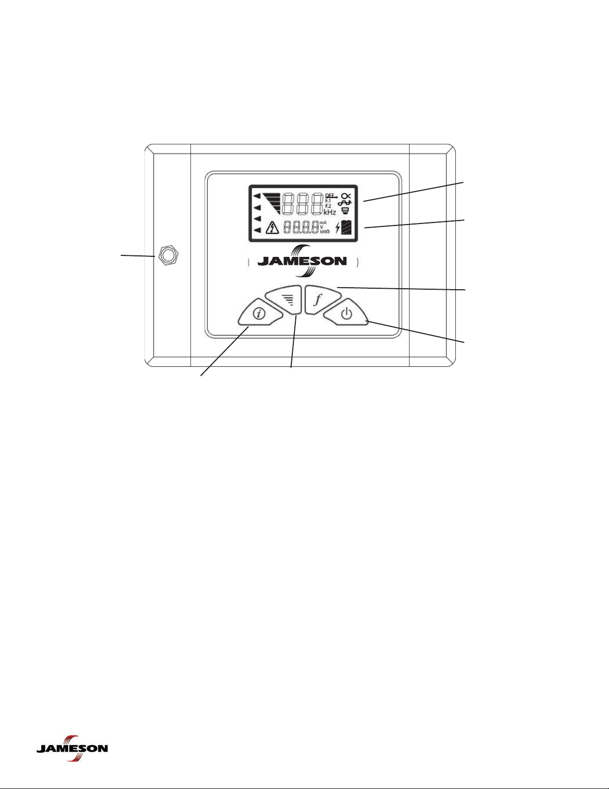
Absolute Signal Strength
The Receiver’s signal strength measurement is displayed with three numerical digits (ex: 485) located at the top
of the LCD display. The measurement range is from 0 to 999 indicating a very weak signal (0) to a very strong
signal (999). Absolute Signal Strength is independent of the Gain setting or meter reading. It gives the operator
information about the actual amount of signal being radiated from the conductor and received by the Receiver.
Measuring Absolute Signal Strength at any time is done by reading the number at the top of the LCD display.
The Absolute Signal Strength will not be displayed if the meter reading is too high or too low. Adjust Gain to
move meter reading to mid-scale. The numerical display will change from ‘---’ to a valid measurement.
Absolute Signal Strength measurements are more sensitive to signal changes than the meter display. Peaks
and Nulls can be more precisely pinpointed. This measurement can also be used to monitor signal loss as the
conductor is being traced.
Passive 50/60 Hz Locating
The Receiver is capable of locating power utility frequencies. This Mode is useful for locating underground
primary and secondary power utilities. In certain circumstances, this Mode will also locate water pipes, sewer
lines, cable television and telephone. The reason is that common electrical grounds are sometimes found
among these various utilities. Select the 50/60~ (Hz) frequency on the Receiver. Select Peak mode. Locate the
conductor using the Peak mode.
This method is useful because of its speed and convenience. Start at a known reference point and keep in mind
other conductors in the area may produce this same locating signal.
The Transmitter is not required to locate in this mode.
Gain Change Indication
The Gain up and down buttons are used to increase and decrease gain in small amounts. If the meter reading
is very low, pressing the Gain up button will center the meter reading to mid-scale. Likewise, if the meter read-
ing is very high, pressing the Gain down button will center the meter reading to mid-scale.