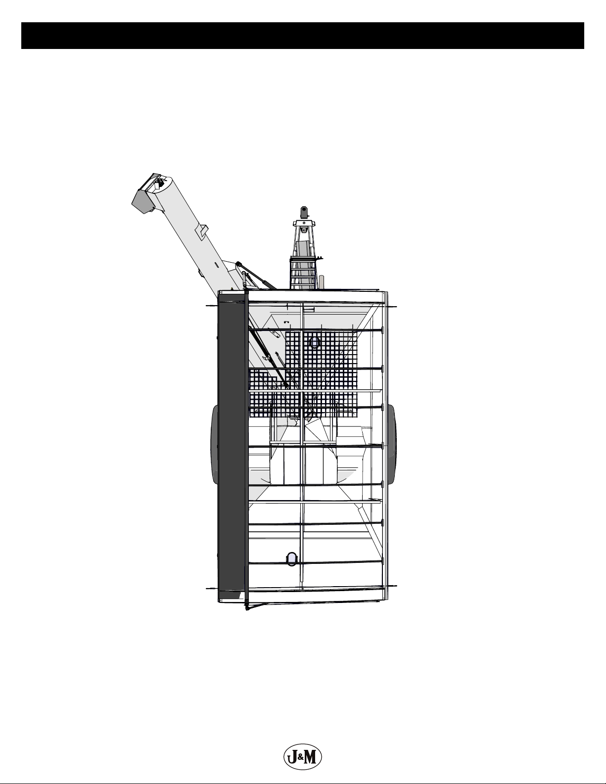
J&M 620 User manual

Rev. 1.30.2020
GRAIN CART
OPERATOR’S MANUAL
MODEL
Manual
J&M Manufacturing Co, Inc
284 Railroad Street - P.O. Box 547 | Fort Recovery, OH 45846 | Ph: (419) 375-2376 | Fax: (419) 375-2708
www.jm-inc.com

2
Stance
Rear
Opposite Auger SideAuger Side
Front

3
Table Of Contents
4..............................................................................................To the Dealer
5.......................................................................................General Information
5.............................................................................Specications and Dimensions
6.....................................................................................................Decals
8..........................................................................................Bolt Torque Chart
8..................................................................Stud and Wheel Nut Torque Specications
9............................................................................................... Safety Rules
10 ........................................................................ Initial Operation and Maintenance
11 ....................................................................................Operating Instructions
12 ..................................................................................Adjusting the Slip Clutch
13 ..............................................................................Lubrication Service Schedule
14 .....................................................................................Routine Maintenance
14 ..........................................................................................Troubleshooting
15 ..................................................................Adjusting the Lower and Upper Flighting
16 ..............................................Removing Dirt from the Restrictors on the Hydraulic Cylinder
16 .......................................................................................Storage Preparation
Repair Parts List and Diagrams
16 ..................................................................................... Wheel Rims and Tires
17 ....................................................................... Non-Scale Hub & Spindle Assembly
18 ............................................................Power Take-O (PTO) Shaft Assembly - Weasler
19 ..................................................................................Self Adjusting Slip Clutch
20 ..................................................................130 Degree Gearbox Assembly - Superior
21 ....................................................................................... Driveline Assembly
22 ..................................................................................Hitch and Jack Assembly
23 ....................................................................................Lower Auger Assembly
24 ........................................................................................Top Auger Linkage
24 ......................................................................................Top Auger Assembly
25 .......................................................................................Flow Control Spout
26 .........................................................................................Lights and Wiring
27 ......................................................................................... Ladder Assembly
28 ...............................................................................Hydraulic Hoses & Cylinders
30 ........................................................Hydraulic Hoses & Cylinders for Auto-Gate Shut-O
32 .............................................................................Auto-Gate Shut-O Assembly
32 .....................................................................Auto-Gate Shut-O Wiring Schematic
33 ......................................................................................3-Point Scale System
34 ...............................................................................................Sideboards
35 .....................................................................................Door Wheel Assembly
35 ......................................................................................Inspection Windows
36 ........................................................................................Roll Tarp Assembly
38 ...................................................................................Spring Return Assembly

4
To the Dealer
Read manual instructions and safety rules. Make sure all items on the Dealer’s Pre-Delivery and Delivery Check Lists are completed
before releasing equipment to the owner.
The dealer must complete the Warranty Registration found on the Dealer Portal website located at dealer.jm-inc.com and return it to J&M
Mfg. Co., Inc. at the address indicated on the form. Warranty claims will be denied if the Warranty Registration has not been submitted.
EXPRESS WARRANTY:
J&M Mfg. Co., Inc. warrants against defects in construction or materials for a period of ONE year. We reserve the right to inspect and
decide whether material or construction was faulty or whether abuse or accident voids our guarantee.
Warranty service must be performed by a dealer or service center authorized by J&M Mfg. Co., Inc. to sell and/or service the type of
product involved, which will use only new or remanufactured parts or components furnished by J&M Mfg. Co., Inc. Warranty service will
be performed without charge to the purchaser for parts or labor based on the Warranty Labor Times schedule. Under no circumstance
will allowable labor times extend beyond the maximum hours indicated in the Warranty Labor Times schedule for each warranty
procedure. The purchaser will be responsible, however, for any service call and/or transportation of the product to and from the dealer
or service center’s place of business, for any premium charged for overtime labor requested by the purchaser, and for any service and/or
maintenance not directly related to any defect covered under the warranty. Costs associated with equipment rental, product down time,
or product disposal are not warrantable and will not be accepted under any circumstance.
Each Warranty term begins on the date of product delivery to the purchaser. Under no circumstance will warranty be approved unless (i)
the product warranty registration card has been properly completed and submitted to the equipment manufacturer, and (ii) a warranty
authorization number has been issued by the equipment manufacturer. This Warranty is eective only if the warranty registration card is
returned within 30 days of purchase.
This Warranty does not cover a component which fails, malfunctions or is damaged as a result of (i) improper modication or repair, (ii)
accident, abuse or improper use, (iii) improper or insucient maintenance, or (iv) normal wear or tear. This Warranty does not cover
products that are previously owned and extends solely to the original purchaser of the product. Should the original purchaser sell or
otherwise transfer this product to a third party, this Warranty does not transfer to the third party purchaser in any way. J&M Mfg. Co.,
Inc. makes no Warranty, express or implied, with respect to tires or other parts or accessories not manufactured by J&M Mfg. Co., Inc.
Warranties for these items, if any, are provided separately by their respective manufacturers.
THIS WARRANTY IS EXPRESSLY IN LIEU OF ALL OTHER WARRANTIES OR CONDITIONS, EXPRESS, IMPLIED OR STATUTORY, INCLUDING ANY
IMPLIED WARRANTY OF MERCHANTABILITY OR FITNESS FOR PARTICULAR PURPOSE.
In no event shall J&M Mfg. Co., Inc. be liable for special, direct, incidental or consequential damages of any kind. The exclusive remedy
under this Warranty shall be repair or replacement of the defective component at J&M Mfg. Co., Inc’s. option. This is the entire agreement
between J&M Mfg. Co., Inc. and the Owner about warranty and no J&M Mfg. Co., Inc. employee or dealer is authorized to make any
additional warranty on behalf of J&M Mfg. Co., Inc.
The manufacturer reserves the right to make product design and material changes at any time without notice. They shall not incur any
obligation or liability to incorporate such changes and improvements in products previously sold to any customer, nor shall they be
obligated or liable for the replacement of previously sold products with products or parts incorporating such changes.
SERVICE:
The equipment you have purchased has been carefully manufactured to provide dependable and satisfactory use. Like all mechanical
products, it will require cleaning and maintenance. Lubricate the unit as specied. Observe all safety information in this manual and
safety signs on the equipment.
For service, your authorized J&M dealer has trained mechanics, genuine J&M service parts, and the necessary tools and equipment to
handle all your needs.
Use only genuine J&M service parts. Substitute parts may void warranty and may not meet standards required for safety and satisfactory
operation. Record the model number and serial number of your equipment in the spaces provided:
Model No: 620 Grain Cart Serial No: ________________________ Date of Purchase: ___________________
Purchased From: ________________________________________________________________________________
Provide this information to your dealer to obtain correct repair parts.

5
General Information
TO THE OWNER:
The purpose of this manual is to assist you in operating and maintaining your grain cart in a safe manner. Read it carefully. It furnishes
information and instructions that will help you achieve years of dependable performance and help maintain safe operating conditions. If
this machine is used by an employee or is loaned or rented, make certain that the operator(s), prior to operating:
1. Is instructed in safe and proper use.
2. Reviews and understands the manual(s) pertaining to this machine.
Throughout this manual, the term IMPORTANT is used to indicate that failure to observe can cause damage to equipment. The terms
CAUTION, WARNING and DANGER are used in conjunction with the Safety-Alert Symbol (a triangle with an exclamation mark) to indicate
the degree of hazard for items of personal safety. When you see this symbol, carefully read the message that follows and be alert to the
possibility of personal injury or death.
DANGER
WARNING
CAUTION
This Safety-Alert symbol indicates a hazard and means
ATTENTION! BECOME ALERT! YOUR SAFETY IS INVOLVED!
Indicates an imminently hazardous situation that, if not avoided, will result in death or serious injury.
Indicates a potentially hazardous situation that, if not avoided, could result in death or serious injury,
and includes hazards that are exposed when guards are removed.
Indicates a potentially hazardous situation that, if not avoided, may result in minor or moderate injury.
Indicates that failure to observe can cause damage to equipment.
Indicates helpful information.
IMPORTANT
NOTE
Specications and Dimensions
SPECIFICATIONS
Single Wheel Option
Capacity
Auger, One Vertical
Unload Time (minutes)
Wheels (2)
Tires (2)
Hubs (2)
Spindles (2)
Tongue Weight
Empty
Loaded
Total Weight (approx.)
620 Bushels
14”
3.7 Minutes
21x32 or 27x32
24.5x32, 30.5x32, or
IF800/60R32
10 Bolt
4-1/2”Diameter
1,000 lbs.
2,100 lbs.
6,950 lbs.
C
D
F
A
I
H
E
B
A
B
C
D
E
F
G
H
I
J
K
L
1’-5”
12’-10”
6-5”
13’-2”
18’-10”
11’-11”
7’-5”
11’-10”
1’-6”
10’-0”/10’-4”/12’-0”
11’-10”
11’-4”
K
L
J
G

6
Decals
DO NOT ENTER GRAIN TANKWHEN
AUGER IS RUNNING.
KEEPOFF THE LADDER WHILE
THEMACHINE IS OPERATING,
INTRANSPORT OR THE
UNLOADINGAUGER IS IN MOTION
3 4 5 6 7
89
11 12
10
DO NOT ENTER GRAIN TANK WHEN
AUGER IS RUNNING.
KEEP OFF THE LADDER WHILE
THE MACHINE IS OPERATING,
IN TRANSPORT OR THE
UNLOADING AUGER IS IN MOTION
FORFARM USE ONLY
14
15
13
8
16
FLOWINGGRAINTRAPS
ANDSUFFOCATES
VICTIMSINSECONDS!
NEVERPLAYINOR ON GRAIN CART
YOUCANDIEIN SECONDS
INFLOWINGGRAIN!
HELP!
FOR FARM USE ONLY
FLOWING GRAIN TRAPS
AND SUFFOCATES
VICTIMS IN SECONDS!
NEVER PLAY IN OR ON GRAIN CART
YOU CAN DIE IN SECONDS
IN FLOWING GRAIN!
HELP!
CHECK ALL WHEEL NUTS
DEALER OR MANUFACTURER IS NOT
RESPONSIBLE FOR DAMAGE CAUSED BY
LOOSE WHEEL NUTS.
CHECK TIRE INFLATION
DO NOT INFLATE TIRES MORE THAN 6 PSI
OVER THE RECOMMENDED PRESSURE
PRINTED ON THE SIDE OF THE TIRE.
WARNING
HIGH PRESSURE FLUID HAZARD
To prevent serious injury or death:
Relieve pressure on system before repairing
or adjusting or disconnecting
Wear proper hand and eye protection when
searching for leaks. Use wood or cardboard
instead of hands.
Keep all components in good repair.
WARNING
DO NOT ADJUST, SERVICE, CLEAN OR LUBRICATE
THE MACHINE UNTIL ALL POWER IS SHUT OFF.
KEEP ALL SAFETY SHIELDS IN PLACE.
KEEP PEOPLE AND OBJECTS CLEAR OF EQUIPMENT
BEFORE APPLYING POWER OR MOVING THE MACHINE.
PREVENT PEOPLE FROM RIDING ON THE MACHINE.
FALLING CAN CAUSE SERIOUS INJURY OR DEATH.
BEFORE HIGHWAY TRAVEL, SECURE A SLOW-MOVING
VEHICLE EMBLEM TO THE REAR OF THE MACHINE.
MAKE SURE ALL FLASHER, TURN INDICATOR AND
BRAKE LIGHTS ARE WORKING PROPERLY BEFORE
HIGHWAY TRAVEL.
CHECKALL WHEEL NUTS
DEALEROR MANUFACTURER IS NOT
RESPONSIBLEFOR DAMAGE CAUSED BY
LOOSEWHEEL NUTS.
CHECKTIRE INFLATION
DONOT INFLATE TIRES MORE THAN 6 PSI
OVERTHE RECOMMENDED PRESSURE
PRINTEDON THE SIDE OF THE TIRE.
WARNING
HIGHPRESSUREFLUID HAZARD
Topreventseriousinjury or death:
Relievepressureonsystem before repairing
oradjustingordisconnecting
Wearproperhandand eye protection when
searchingforleaks. Use wood or cardboard
insteadofhands.
Keepallcomponentsin good repair.
WARNING
DONOTADJUST, SERVICE, CLEAN OR LUBRICATE
THEMACHINEUNTIL ALL POWER IS SHUT OFF.
KEEPALLSAFETY SHIELDS IN PLACE.
KEEPPEOPLEAND OBJECTS CLEAR OF EQUIPMENT
BEFOREAPPLYINGPOWER OR MOVING THE MACHINE.
PREVENTPEOPLEFROM RIDING ON THE MACHINE.
FALLINGCANCAUSE SERIOUS INJURY OR DEATH.
BEFOREHIGHWAYTRAVEL, SECURE A SLOW-MOVING
VEHICLEEMBLEMTO THE REAR OF THE MACHINE.
MAKESUREALL FLASHER, TURN INDICATOR AND
BRAKELIGHTSARE WORKING PROPERLY BEFORE
HIGHWAYTRAVEL.
1
2
ATTENTION! BECOME ALERT! YOUR SAFETY IS INVOLVED!
Replace Immediately If Damaged or Missing
Description Part No.
1 J&M Oval Decal (Medium) 5-1/2” x 8-1/2” JM0010179
2 www.jm-inc.com Decal JM0019239
3 Danger, Do Not Enter Grain Tank Decal JM0018033
4 Danger, Keep O Ladder Decal JM0018034
5 Warning, Keep Hands Away Decal JM0018039
6 Closed Decal JM0025434
7 Open Decal JM0025433
8 Danger, Electric Lines Decal JM0015099
9 J&M Oval Decal (Large) 9-1/2” x 15” JM0015151
10 Warning, Do Not Adjust Or Service Decal JM0014979
11 Warning, High Pressure Fluid Hazard Decal 4” x 4” JM0010163
12 Check Tire Ination Decal JM0018041
13 Check All Wheel Nuts Decal JM0018043
14 Important Operating Instructions Yellow Grain Cart Decal JM0021245
15 For Farm Use Only Decal JM0018038
16 Danger, Flowing Grain Traps Grain Cart Decal JM0018037

7
Decals
22
17
21
21
13
19
8
918
CHECK ALL WHEEL NUTS
DEALER OR MANUFACTURER IS NOT
RESPONSIBLE FOR DAMAGE CAUSED BY
LOOSE WHEEL NUTS.
Ground
Rear Of Plug
Notes
Grain Cart Light Harness
Tail/RunningLights
+12V Output
Min.15A Fuse
Flow Control Spout/
Implement Lights
LeftTurn & Hazards
RightTurn & Hazards
N/A
The follow equipment will need the
+12VOutput to function properly.
•Lock-N-Load Flighting Protection
•Scale Equipment
•Electric Roll Tarp Charging System
To activate the Flow Control Spout
Light,turn on your clearance or
implementlights and fully extend
augerto the unloading position.
Pleaserefer to your tractors operators
manualfor specic instructions.
Lookfor these icons in your tractor
Hydraulic Hoses
Hydraulic Requirements:
• 9 - 12 GPM
• Auto Gate (if equipped): Set Gate to continuously close. Refer to your tractors
operatorsmanual for specic instructions.
Warning:
H ydraulicsystem parts and connec tions can containhigh pressures which, if
suddenlyand unexpectedly released, can cause serious injur y or death.
GateAuger Fold/UnfoldFlow ControlSpout
GCJM0041058
RED YELLOW GREEN
1
2
3
4
5
6
7
Ground
RearOfPlug
Notes
GrainCartLightHarness
Tail/RunningLights
+12VOutput
Min.15AFuse
FlowControlSpout/
ImplementLights
LeftTurn&Hazards
RightTurn&Hazards
N/A
Thefollowequipmentwillneedthe
+12VOutputtofunctionproperly.
•Lock-N-Load Flighting Protection
•Scale Equipment
•Electric Roll Tarp Charging System
ToactivatetheFlowControlSpout
Light,turnonyourclearanceor
implementlightsandfullyextend
augertotheunloadingposition.
Pleaserefertoyour tractors operators
manualforspecic instructions.
Lookfortheseiconsinyourtractor
HydraulicHoses
HydraulicRequirements:
•9-12GPM
•AutoGate(ifequipped): Set Gate to continuously close. Refer to your tractors
operatorsmanualforspecicinstructions.
Warning:
Hydraulicsystempartsandconnec tions can containhigh pressures which, if
suddenlyandunexpectedlyreleased,cancause serious injury or death.
Gate
AugerFold/Unfold
FlowControlSpout
GCJM0041058
RED YELLOW GREEN
1
2
3
4
5
6
7
2
1
20
Description Part No.
17 620 Opposite Auger Side Stripe Kit JM0025939
18 620 Auger Side Stripe Kit JM0025938
19 Check PTO Overlap Decal JM0025435
20 Grain Cart Light Harness Decal (Standard Fold Carts) JM0041058
21 Danger, Rotating Driveline Decal JM0018036
22 Danger, Keep Hands and Clothing Away Decal JM0018035

8
Bolt Torque Chart
TIGHTENING WHEEL NUTS: Standard 3/4” wheel studs and nuts should be tightened to torque 400 ft-lbs. During initial operation of
the grain cart and then checked for proper torque after every 10 hours of use. Failure to do so may damage wheel nut seats. Once seats
are damaged, it will become impossible to keep nuts tight.
Always tighten hardware to these values unless a dierent torque or tightening procedure is listed for specic application. Fasteners must
always be replaced with the same grade as specied in the manual parts list. Always use the proper tool for tightening hardware. Make
sure fastener threads are clean and you start thread engagement properly. Use these values when tightening all bolts and nuts with
the exception of wheel nuts.
Stud and Wheel Nut Torque Specications
Always tighten hardware to these values unless a dierent torque or tightening procedure is listed for specic application. Fasteners must
always be replaced with the same grade as specied in the manual parts list. Always use the proper tool for tightening hardware. Make
sure fastener threads are clean and you start thread engagement properly. Use these values when tightening all studs and wheel
nuts.
SAE Fasteners
Coarse Thread Series
Grade 5 Grade 8
Diameter and Pitch (Inches) Dry Oiled Dry Oiled
1/4”-20 8 ft-lbs 6 ft-lbs 12 ft-lbs 9 ft-lbs
5/16”-18 17 13 25 18
3/8”-16 30 23 45 35
7/16”-14 50 35 70 55
1/2”-13 75 55 110 80
9/16”-12 110 80 150 110
5/8”-11 150 110 220 170
3/4”-10 260 200 380 280
7/8”-9 430 320 600 460
1”-8 640 480 900 680
Fine Thread Series
Diameter and Pitch (Inches) Dry Oiled Dry Oiled
1/4”-28 10 ft-lbs 7 ft-lbs 14 ft-lbs 10 ft-lbs
5/16”-24 19 14 29 20
3/8”-24 35 25 50 40
7/16”-20 55 40 80 60
1/2”-20 90 65 120 90
9/16”-18 120 90 170 130
5/8”-18 180 130 240 180
3/4”-16 300 220 420 320
7/8”-14 470 360 660 500
Stud Tightening Torque
1/2”-20 120 ft-lbs
9/16”-18 170 ft-lbs
5/8”-18 300 ft-lbs
3/4”-16 400 ft-lbs
20mm 475 ft-lbs
22mm 640 ft-lbs

9
Safety Rules
ATTENTION! BECOME ALERT! YOUR SAFETY IS INVOLVED!
Safety is a primary concern in the design and manufacture of our products. Unfortunately, our eorts to provide safe equipment can
be erased by an operator’s single careless act. In addition, hazard control and accident prevention are dependent upon the awareness,
concern, judgment, and proper training of personnel involved in the operation, transport, maintenance and storage of equipment.
Make certain the operator(s), prior to operating, is instructed in safe and proper use and reviews and understands the manual(s)
pertaining to this machine. Also make certain the operator(s) reviews and understands the operator’s manual of the tractor prior to
hooking up or operating the grain cart.
Read this manual before you operate this machine. If you do not understand any part of this manual, or need more information, contact
J&M Mfg. Co., Inc. or your authorized dealer.
SAFETY
Understand that your safety and the safety of other persons is measured by how you service and operate this machine. Know the
positions and functions of all controls before you try to operate them. Make sure to check all controls in a safe area before starting your
work.
The safety information given in this manual does not replace safety codes, federal, state or local laws. Make certain your machine has the
proper equipment as designated by local laws and regulations.
A frequent cause of personal injury or death is from persons falling o equipment and being run over. Do not permit persons to ride on
this machine.
Travel speeds should be such that complete control and machine stability is maintained at all times. Where possible, avoid operating
near ditches, embankments and holes. Reduce speed when turning, crossing slopes and rough, slick or muddy surfaces.
Collision of high speed road trac and slow moving machines can cause personal injury or death. On roads, use asher lights according
to local laws. Keep slow-moving-vehicle emblem visible. Pull over to let faster trac pass.
Hydraulic oil leaking under pressure can penetrate skin and cause infection or other injury. To prevent personal injury,
• Relieve all pressure, before disconnecting uid lines,
• Before applying pressure, make sure all connections are tight and components are in good condition,
• Never use your hand to check for suspected leaks under pressure. Use a piece of cardboard or wood for this purpose.
• If injured by leaking uid, see your doctor immediately.
When transporting the grain cart, always keep the auger in the stow position.
Use care when moving of operating the grain cart near electric lines as serious injury or death can result from contact.
Never adjust, service, clean, or lubricate the grain cart until all power is shut o. Keep all safety shields in place. Keep hands, feet, hair
and clothing away from moving parts while the grain cart is in operation.
The service ladder is for service work only. If you must climb into the grain tank, be certain that all power is shut o and then use
extreme caution when climbing into the grain cart.
Make sure that everyone is clear of equipment before applying power or moving the machine.
Make sure the grain cart is fastened securely to the tractor using a high strength hitch pin, clip and safety chains. Make sure the grain
cart hitch properly matches the hitch type of the tractor. Use a single prong (spade) grain cart hitch with a double prong (clevis) tractor
hitch. Use a double prong (clevis) grain cart hitch with a single prong (spade) tractor hitch. Be sure the tractor pin is at least 1/4”smaller
in diameter than the pin hole in the grain cart hitch to ensure enough free movement when traversing through uneven terrain.
Before lling the grain cart, make certain no one is inside the grain tank. Never allow children, or anyone, in, near, or on the grain
cart during transport or during loading and unloading of grain. Be aware that moving grain is dangerous and can cause entrapment,
resulting in severe injury or death by suocation.
Never operate the auger system with anyone inside the grain tank. Hands, feet, hair and clothing can t through the openings in and
around the grate. Contact with the auger can cause severe injury or death. Ensure all power is shut o before service work is performed.
Before unhooking the grain cart from the tractor, be sure the jack stand is properly mounted and in place and the wheels are properly
blocked to prevent the cart from moving.

10
Initial Operation and Maintenance
WARNING
BE CERTAIN THAT ALL POWER IS SHUT OFF BEFORE SERVICING THE GRAIN CART.
Before the grain cart is put into service:
• Have the safety instructions been read and clearly understood by the operator(s) of this machine?
• Has the gearbox been properly lled with SAE 80W-90 gearbox lubricant?
• Have all nuts, bolts, bearings and braces been properly fastened?
• Has the PTO been checked for proper overlap?
IMPORTANT: Has the slip clutch on the PTO been serviced? If the slip clutch is left unchecked, damages to the power-take-o and drive
shaft may result. Before using the grain cart, loosen the bolts around the slip clutch. Make sure the friction plates turn free of each other
and are not corroded together. Re-tighten the tension bolts. Run the auger system EMPTY and check for proper engagement of the slip
clutch.
CHECK PTO OVERLAP LENGTH. Overlap length may vary depending on the tractor model and hitch setting. Try to obtain the greatest
possible overlap without bottoming out in the extreme operating conditions. Too much overlap may cause the PTO to bottom out and
damage the driveline. Not enough overlap may cause the PTO front and back halves to separate. From the fully compressed (shortest)
length the PTO should be telescoped (extended) between 10”and 22”. Dierent PTO lengths may need to be purchased to accommodate
your terrain. A 4”shorter or a 10”longer PTO can be ordered through your dealer from J&M Manufacturing.
GREASE BEARINGS: Are all bearings on the driveline properly greased? Are all set screws in the bearings and U-joints tight? Has the
PTO shaft been properly greased at all points including the cross bearings? Has the universal joint at the gearbox been greased? Have all
grease points at the auger hinge area, including the hanger bushing assembly been greased?
TIRE PRESSURE: Are the tires properly inated? The following is to be used as a general guide for tire ination for cyclic use. Figures
can vary depending on specic brand of tire used. It is important that tires are inspected before and after the unit is loaded. The
tire should stand up with no side wall buckling or distress as the tire rolls. Do not exceed the tire pressure indicated below:
Tire psi
24.5x32 Lug Tires-12 ply (Firestone) (for 21x32-10 Hole Wheels) 24
24.5x32 Diamond Tires-12 ply (Firestone) (for 21x32-10 Hole Wheels) 24
30.5x32 Lug Tires-14 Ply (Firestone) (for 27x32-10 Hole Wheels) (124” c/c) 28
30.5x32 Lug Tires-18 ply (Alliance) (for 27x32-10 Hole Wheels) (124” c/c) 36
IF800/60R32 Diamond Tires (Firestone) (181B) (for 27x32-10 Hole Wheels) 46

11
Operating Instructions
VERY IMPORTANT: Under no circumstance is it recommended to tow a loaded grain cart in excess of 8 mph.
WHEEL NUTS: Are the wheel nuts properly fastened? Torque to 400 Ft.-Lbs. for 3/4” wheel studs and nuts. Wheel studs and nuts
should be checked after each load during initial operation of the cart and then after every 10 hours of use. Failure to do so may
damage wheel studs and nuts. Once the seats are damaged, it will become impossible to keep the lug nuts tight.
The drawing shows the proper way to mount the wheels using Budd-type nuts. The wheels supplied with
your grain cart have straight holes and the Budd nuts will be mounted according to Figure 1. Wheels that
are improperly installed on the grain cart, resulting in product failure, will nullify warranty and shift the
burden of liability to the owner/operator. We recommend you inspect your wheel nuts to make sure they
are properly installed. Also, check the wheel nuts on a regular basis to ensure they are tight.
LIGHTING AND SAFETY DECALS: Are the rear, amber extremity lights properly positioned? Extend the lights within 16” (40,6cm) of the
left and right extremities of the grain cart. Is an SMV Emblem attached to the rear of the grain cart?
Are the lights working properly? Are all lights and reective decals clean, visible and properly placed?
BE CERTAIN THAT ALL POWER IS SHUT OFF WHEN HOOKING UP TO TRACTOR OR CONNECTING HYDRAULIC LINES TO TRACTOR.
Tractor requirements for proper towing: Model 620 grain carts require a minimum of 130 HP tractor.
IMPORTANT: Do NOT pull a loaded grain cart on highway. For incidental highway travel, observe the section below.
Tow Loads Safely
Stopping distance increases with speed and weight of towed loads, and on slopes. Towed loads with or without brakes that are too
heavy for the tractor or are towed too fast can cause loss of control. Consider the total weight of the equipment and its load.
Observe these recommended maximum road speeds, or local speed limits which may be lower:
• Grain cart empty: Do not travel more than 20 mph (32 km/hr) and do not tow loads more than 1.5 times the pulling unit’s weight.
• Grain cart loaded: Do not travel more than 8 mph (12 km/hr) and do not tow loads more than 1.5 times the pulling unit’s weight.
Ensure the load does not exceed the recommended weight ratio. Use additional caution when towing loads under adverse surface
conditions, when turning, and on inclines.
WARNING: For greater stability on uneven or steep terrain, position non-scale wheel spindles at the furthest out setting.
IMPORTANT:
1. Connect grain cart hitch to tractor drawbar using a good quality hitch pin. Attach the safety chain to the tractor and through one
chain loop provided on either side of the grain cart frame as shown. Make sure the grain cart hitch properly matches the hitch of the
tractor. Use a single prong (spade) grain cart hitch with a tractor double prong (clevis) hitch. Use a double prong (clevis) grain cart
hitch with a single prong (spade) tractor hitch.
Safety Chain User Instruction
a) Secure the safety chain by looping it around each side of the grain cart as shown and connecting to
the towing machine’s attaching bar.
b) Do not allow any more slack than necessary for articulation.
c) Do not use any intermediate support as the attaching point.
d) Store the safety chain by securing it around the main axle A-frame of the grain cart.
e) Replace the safety chain if one or more links or end ttings are broken, stretched or otherwise
damaged or deformed.
2. Attach the power-take-o shaft to the tractor. The PTO must have at least 10” of engagement. Check tractor drawbar for clearance
and length and adjust if necessary. Make sure the PTO does not bottom out when making sharp turns as it may bend the drive
shaft.
3. Make sure the jack stand is repoitioned from the lower support position before the cart is moved. Never use the jack to support a
loaded grain cart.
4. Be sure that no debris or foreign objects are in the grain cart.
Figure 1

12
Operating Instructions
5. Attach the hydraulic lines to the tractor. Two hydraulic lines (green band) operate the inside gate mechanism. Connect these lines
to one service outlet on the tractor. Two hydraulic lines (yellow band) operate the folding mechanism of the auger. Connect these
lines to a second service outlet on the tractor. The remaining two hydraulic lines (red band) operate the hydraulic ow control spout
located at the end of the upper auger. Connect these lines to a third service outlet on the tractor. Make sure the air is bled from the
hydraulic cylinders and hoses.
6. Run the auger system EMPTY before loading grain into the tank for actual use. Make certain that the upper and lower augers are
properly engaged.
7. Connect the lighting 7-prong connector end on the main wiring harness to the tractor electrical outlet. Make sure that all asher
and turn indicator lights are working properly before incidental highway travel.
CAUTION
• Do NOT operate the grain cart before reading and understanding this Operator’s Manual and ALL danger, warning and caution signs.
• Be sure that a Slow-Moving-Vehicle emblem is attached to the rear of the grain cart.
• Never exceed 1,000 rpm on the PTO and driveline system.
• Never fold or extend the auger until the PTO has come to a complete stop.
• Never ll the grain cart unless the gate indicator is in the closed position.
• Never allow foreign objects (shovels, etc.) to be placed inside the grain cart.
• Never engage the lugs and drive dogs on the augers when the system is moving at a high rate of speed.
• Never perform maintenance work or service the grain cart with the tractor running.
1. Make sure the tractor is o and the PTO is
disengaged.
2. Disconnect the driveline from the tractor.
3. Locate the six (6) long bolts (item 8 in diagram) on
the O.D. of the clutch pack. Loosen the bolts until
they rotate freely, nger tighten each bolt, and then
tighten each bolt one half turn.
4. Attach the implement to the tractor with a hitch
pin and the drive line to the tractor PTO shaft.
5. Start the tractor. Engage the PTO and run a few
seconds, or until the friction clutch visibly smokes.
6. Disengage the tractor PTO and shut the tractor o.
7. Disconnect the driveline from the tractor.
8. Tighten the six (6) long bolts (item 8 in diagram) on
the O.D. of the clutch pack until the compression
plate (item 7 in diagram) is in contact with the
housing (item 1 in diagram), then keep tightening
each bolt to 30 ft.-lbs.
9. Locate the four (4) short bolts (item 10 in diagram)
that attach the yoke & hub (item 12 in diagram)
to the clutch pack and check that each bolt is
tightened to 30 ft.-lbs.
Adjusting the Slip Clutch

13
Lubrication Service Schedule
IMPORTANT: Your grain cart has grease ttings at all critical points. These should be serviced before the grain cart is put into operation.
WARNING
BE CERTAIN THAT ALL POWER IS SHUT OFF BEFORE SERVICING THE GRAIN CART
PTO & DRIVELINE: The grease ttings on the PTO should be serviced after every 8 hours of use. Service the grease ttings on each of
the drive bearings and also the universal joint after every 8 hours of use.
AUGER FOLDING MECHANISM: One grease tting is located on the pivot pin of the folding auger. This tting should be serviced after
every 8 hours of use. Service the grease tting on the hanger bushing assembly (top end of the lower auger assembly) after every 8
hours of use or as needed.
SPRING LOADED UPPER AUGER BEARING: Service the grease tting on the upper auger bearing (located at the top end of the upper
auger assembly) after every 8 hours of use. Lubricate the springs and retaining bolts on the bearing before prolonged storage of the
grain cart.
GEARBOX: Gearbox lubricant has been added to the gearbox during nal assembly. Recheck the lubricant level before initial operation
of the grain cart, then periodically according to use. An inspection plug is located in the center of the top of the gearbox mount plate.
To check the uid level, remove the vented inspection plug and drain plug at the bottom of the gearbox. Drain the lubricant. Return
the drain plug and rell the gearbox with 24 ounces (0,71 liters) of gearbox lubricant. DO NOT OVERFILL. Use SAE 80W-90 gearbox
lubricant or equivalent. Change the oil annually before use.
Gearbox Lubricant
Model Ounces Input Shaft Output Shaft
620 24 1-3/4” 1-3/4”
Grease Fittings
Pivot Pin Once Annually
Roll Tarp U-Joint Once Annually
Upper Auger Flighting Every 8 hrs of use
Driveline Every 8 hrs of use
Drive Dog Every 8 hrs of use

14
Troubleshooting
WARNING
BE CERTAIN ALL POWER IS SHUT OFF WHEN SERVICING THE GRAIN CART
• Repack the bearings in the hub assembly once a year or as needed. Use a good quality LS EP2 severe duty, high shock load, lithium-
based grease. Also check the seal for wear and replace if necessary.
• Check the grain cart periodically for cracks in welds and for other structural damage. Have cracked welds xed immediately. Failure to
do so could result in extensive damage to the grain cart and greatly reduce the life of the cart.
• Lubricate the slides on the clean-out door.
• Check all hydraulic hoses for wear and replace as necessary.
• Make sure all tires are properly inated. See “Initial Operation and Maintenance”on page 10 in the Owner’s Manual for recommended
instructions for tire pressure. It is important that tires are inspected before and after unit loaded.
• Check PTO for wear of plates in the slip clutch. Replace if needed.
• Make sure that all guards and shields are in place before operating the grain cart.
Routine Maintenance
WARNING
MAKE SURE THAT ALL POWER IS SHUT OFF BEFORE SERVICING THE GRAIN CART. MAINTENANCE AND REPAIR SERVICE WORK TO BE
PERFORMED BY QUALIFIED SERVICE PERSONNEL ONLY.
Trouble Possible Cause Possible Remedy
Auger will not return to down
position or move from stow
position
Faulty check valve Replace check valve
Faulty lock and load solenoid Disconnect power to lock and load. If the auger is able to move, the lock and
load solenoid needs to be replaced
Upper ighting and lower ighting
are locked together
Bearing on top of upper auger ighting needs adjusting. When the auger is in
the engaged position, there must be 1/8”(0,32cm) gap between bottom of top
bearing and top of upper tube housing (See “Adjusting the Lower and Upper
Flighting”on page 15)
Feed gate open Close the feed gate
Lock and Load not operating
correctly
Make sure the limit switch on the feed gate indicator assembly is functioning
properly
Hanger bushing assembly at
the top of the lower auger
ighting is hot
Top of the hanger bushing
assembly is rubbing against the
drive dog
Loosen the two bolts and re-adjust the position of the hanger bushing assembly.
Re-tighten bolts
Remove the lower ighting assembly and place a shim between the spline
coupler and the gearbox
Excessive vibration Auger ighting or shaft is bent Straighten or replace auger ighting
Drive shaft is bent Replace or straighten drive shaft
Grain ow stoppage
Bolt sheared in drive dog Replace bolt in drive dog. Engage upper and lower ighting at a slow rate of
speed. (Drive dogs and lugs are being engaged too fast.)
Folding auger before complete stop Upper and lower ightings are disengaging before auger comes to a complete
stop. Replace bolt in the drive dog. Never engage or disengage the upper and
lower ightings until the augers come to a complete stop.
PTO key sheared Replace key and tighten set screw
Auger tube is breaking away
from the grain cart at the
hinge area or the ram in the
hydraulic folding cylinder is
bent
Upper auger is extended in the
upright position while traveling in
the eld
Repair or place folding cylinder if necessary. Remember to lower auger to the
eld position after unloading.

15
Adjusting the Lower and Upper Flighting
WARNING
MAKE SURE THAT ALL POWER IS SHUT OFF BEFORE ADJUSTING THE FLIGHTING ASSEMBLY.
LOWER FLIGHTING - If the drive-dog and hanger assembly are becoming excessively hot during unloading, the lower ighting and/or
hanger may need adjusting. The hanger bushing assembly has elongated holes where it attaches to the outer tube assembly. Loosen
the two 1/2”bolts on the hanger bushing assembly. Adjust the hanger either up or down and vertically center it between the ighting
and drive dog. Re-tighten the bolts. Make certain that the ighting center and drive-dogs do not rub the hanger bushing assembly,
causing them to become hot.
If the hanger can no longer be adjusted by moving it up or down on the elongated holes, both the hanger bushing assembly and the
lower ighting will have to be removed. After removing them from the tube assembly, place a shim [between 1/8”(0,32cm) to 3/16”
(0,48cm) thick] next to the gearbox and the spline coupler (welded to the lower ighting). Replace the lower ighting and reattach the
hanger to the tube assembly. Readjust the hanger assembly. NOTE: The bottom of the lower ighting is not attached to the gearbox
with any bolts or set screws but may be‘frozen’fast. Be careful when removing the lower ighting from the gearbox. For easier removal
of the lower ighting, keep the gearbox at the bottom intact, remove the two 1/2”bolts from the hanger bushing assembly and pull the
lower ighting o of the gearbox.
After adjusting the lower ighting, move the upper auger to the unload position and check the upper ighting for readjustment.
UPPER FLIGHTING - If the upper and lower augers to do not properly separate during the unfolding sequence, the upper ighting
may need adjusting. Before making adjustment to the upper ighting, check to see if the lugs and drive dogs on the auger assemblies
are locking together. If they are not locked together, check to see if a faulty check valve on the hydraulic cylinder used to raise and lower
the upper auger assembly may be causing the problem.
Fold the upper tube assembly into the upright position. Position the upper ighting in the engaged position with the lower ighting.
Locate the four-hole ange bearing on the top of the upper auger tube housing. With the upper ighting in the engaged position,
check the spacing between the upper bearing and the upper tube housing. There must be an 1/8”(0,32cm) space between the base of
the four-hole ange bearing and the upper tube housing. If there is NOT a space between the bearing and the upper tube housing, or
if there is more than 1/8”(0,32cm) space, the upper ighting will need to be adjusted. To adjust the upper ighting, loosen the 1-1/4”
hex nuts both above and below the four-hole ange bearing. Move the 1-1/4”hex nuts up or down the threaded shaft on the top of the
auger ighting shaft until the bearing moves to approximately 1/8”(0,32cm) above the base of the upper tube housing. When the four-
hole ange bearing is properly located, tighten both 1-1/4”hex nuts together to secure the bearing position.
If the upper and lower ighting still do not separate properly during the folding sequence, a small bevel may need to be removed from
the inside of the lugs where they engage the drive dogs on the auger assemblies. Grind approximately 1/8”(0,32cm) from the corner of
the lugs where they touch against the drive dogs.
1. Untighten the
1-1/4” hex nut at
least 1/4”.
2. Tighten the 1-1/4”
hex nut until there is
a 1/8” to 3/16”gap
between the 4 hole
ange bearing and
the headpan.
1/8”-3/16”
3. Tighten the 1-1/4”
hex nut back up.
Adjusting Upper Auger

16
Removing Dirt from the Restrictors on the Hydraulic Cylinder
WARNING
MAKE SURE THAT ALL POWER IS SHUT OFF AND THE UPPER AUGER TUBE IS IN THE DOWN POSITION BEFORE REMOVING THE
RESTRICTORS
Remove restrictors from the 90 degree elbow on the tip spout hydraulic cylinder. Remove dirt from the tting to allow hydraulic oil
to ow through the restrictor. Reattach the restrictor to the street elbow. Use Teon sealant tape or equivalent on the threads of the
restrictor before re-attaching.
If the restrictor continues to plug with dirt, replace the restrictor or lter the hydraulic oil in your system.
Storage Preparation
IMPORTANT: When the grain cart is not going to be used for a period of time, store the cart in a dry, protected place. Leaving your grain
cart outside, open to the weather will shorten its life.
Procedure for Storage Preparation
1. Cover electronic monitor (if equipped) with plastic before washing the grain cart. Wash or clean and completely lubricate the grain
cart. See“Lubrication Service Schedule”on page 13.
2. Remove all grain from inside the grain tank, auger tube assemblies, and at the clean-out door.
3. Check the gearbox oil and replace with new SAE 80W-90 gearbox lubricant or equivalent if necessary.
4. Touch up areas where paint may have worn away. Use a good quality primer paint, especially before re-applying graphite paint to
the interior slopes of the grain tank.
5. Retract all hydraulic cylinders to prevent the piston rods from rusting.
6. Clean the tires before storage. Inate the tires at regular intervals.
7. Open the clean-out doors at the base of the grain tank.
Removing from Storage
1. Check the gearboxes to make sure they have the appropriate amount of oil.
2. Inate the tires to the correct operating pressure.
3. Close the clean out doors at the base of the grain tank.
4. Make sure all safety shields are in the proper position.
Repair Parts List and Diagrams
When performing maintenance work, wear sturdy, rough-soled work shoes and protective equipment for eyes, hair, hands, hearing and
head. Follow the instructions in this Operator’s Manual to ensure safe and proper maintenance and repair.
Your local, authorized dealer can supply genuine replacement parts. Substitute parts that are not genuine may not meet original
equipment specications and may be dangerous.
WARNING
MAKE SURE ALL POWER IS SHUT OFF BEFORE PERFORMING ANY MAINTENANCE OR REPAIR WORK.
Wheel Rims and Tires
Wheel Rims for Single Wheel Carts
21x32-10 Hole Wheel Rims
27x32-10 Hole Wheel Rims
Tires for Single Wheel Carts
24.5x32 Lug Tires-12 ply (Firestone) (for 21x32-10 Hole Wheels)
24.5x32 Diamond Tires-12 ply (Firestone) (for 21x32-10 Hole Wheels)
30.5x32 Lug Tires-14 Ply (Firestone) (for 27x32-10 Hole Wheels) (124” c/c)
30.5x32 Lug Tires-18 ply (Alliance) (for 27x32-10 Hole Wheels) (124” c/c)
IF800/60R32 Diamond Tires (Firestone) (181B) (for 27x32-10 Hole Wheels)

17
Description Part No.
1 W-881 Hub Assembly Complete with 3/4”Studs and Nuts (Less Seal and Spindle) JM0050402
2 1”-8 Gr2 Z Centerlock Hex Nut JM0002149
3 1”-8 x 7” Gr5 Z Hex Bolt JM0016689
4 Spindle, 4-1/2” x 30-1/2” for Standard Axle (525-875) JM0018794
5 Seal (4-1/4” ID, 6”OD) for Hub (CR-43771) JM0018955
6 Large Bearing (HM218248) JM0018849
7 Large Race (HM218210) JM0018848
8 W-881 Hub with Large and Small Races, 3/4”Studs & Nuts (11.13 Pilot) JM0020510
9 Wheel Stud (3/4”-16 x 1-3/4”) 913564 JM0018957
10 Wheel Nut 3/4”-16 JM0018958
11 Small Race (HM212011) JM0018854
12 Small Bearing (HM212049) JM0018852
13 2-1/8” ID, 3-3/4” OD Flat Washer (3/16”) JM0015900
14 2”-12 Gr5 Z Castle Hex Nut (912973) JM0015899
15 3/8” x 2-3/4” Z Roll Pin (905945) JM0018956
16 Dust Cap 6-1/4”OD (for W-881 & W-891 Hub) (909921) JM0018954
17 1/4”-20 x 1” Gr5 Z Hex Bolt JM0002095
Non-Scale Hub & Spindle Assembly
Torque Values
3/4" Studs 400 Ft.-Lbs.
8
2 4
5
6
3
9
7 15
10
1
1311
12 14
16
17

18
Power Take-O (PTO) Shaft Assembly - Weasler
Description Part No.
1 Front Half Weasler PTO (1-3/8”) (Slip Clutch) (91-1400-F-138) JM0026025
2 Front Half Weasler PTO (1-3/4”) (Slip Clutch) (91-1400-F-134) JM0026026
3 Back Half Weasler PTO with Slip Clutch, Self Adjusting (97-18615B) JM0026027
4 14R Cross Kit Weasler (PTO or U-Joint) (03-1134) JM0024310
5 Friction Disc, Weasler PTO (2 Required) (11-10143) (1997 and Earlier) JM0026029
5 Friction Disc, Weasler PTO (2 Required) (11-11167) (1997 and Later) JM0026031
6 Complete Shield with Nylon Bearing Retainer (1628ICS) JM0026032
6 Front Half Shield with Retainer (Weasler, Slip Clutch) (1628ICS-F) JM0026033
6 Back Half Shield with Retainer (Weasler, Slip Clutch) (1628ICS-B) JM0026034
7 Yoke & Tube Assembly (PTO) (Weasler) (30”) (98-15972) JM0026035
8 Spring-Lok Yoke (Weasler, Slip Clutch) 1-3/8” (14122-1012) JM0026036
9 Spring-Lok Yoke (Weasler, Slip Clutch) 1-3/4” (14011-1960) JM0026037
10 Yoke & Shaft Assembly (PTO) (Weasler) (99-16281) JM0026038
11 Weasler PTO 1-3/8” Complete (Slip Clutch) (91-1400-138) JM0026039
11 Weasler PTO 1-3/4” Complete (Slip Clutch) (91-1400-134) JM0026045

19
Self Adjusting Slip Clutch
Description Part No.
1 Housing for Weasler PTO Slip Clutch (11-01HS) JM0026046
2 Friction Disc, Weasler PTO (2 Required) (11-11167) (1997 and Later) JM0026031
3 Separator Plate (Weasler PTO Slip Clutch) (11-02SP) JM0026047
4 Friction Disc, Weasler PTO (2 Required) (11-11167) (1997 and Later) JM0026031
5 Pressure Plate (Weasler PTO Slip Clutch) (11-05PP) JM0026048
6 Bell Spring Washer (Weasler PTO Slip Clutch) (11-06SP) JM0026049
7 Compression Plate (Weasler PTO Slip Clutch) (11-07CP) JM0026050
8 Long Bolt (Weasler PTO Slip Clutch) (11-08LB) JM0026051
9 Nut (Weasler PTO Slip Clutch) (11-09NT) JM0026052
10 Short Bolt (Weasler PTO Slip Clutch) (11-10SB) JM0026053
11 Lock Washer (Weasler PTO Slip Clutch) (11-11LW) JM0026054
12 Yoke & Hub Assembly (Weasler PTO Slip Clutch) (11-12YH) JM0026055
13 Slip Clutch Complete (Weasler PTO Slip Clutch) (Includes Yoke & Hub) (11-13SC) JM0026056

20
130 Degree Gearbox Assembly - Superior
Description Part No.
1 Superior Gearbox Seal 1-3/8” (CR13569) (513569) JM0025086
2 Output Shaft for Superior Gearbox, 8-3/8” Long (14-16”) (H00111-02) JM0025079
3 Bearing Cup for Superior Gearbox (14-20”) (414276) JM0025077
4 Bearing Cone for Superior Gearbox (14-20”) (514137) JM0025078
5 29 Tooth Gear for Superior Gearbox (14-16”) (H51S29) JM0025083
6 End Cap for Superior Gearbox (14-20”) (400301) JM0025076
7 Plain Plug for Superior Gearbox (200300) JM0025075
8 Vented Plug for Superior Gearbox (2003PR) JM0025081
9 Bushing (1/2” x 1/4” reducer) for Superior Gearbox (4003VB) JM0025073
10 2-1/4”Bolt for Superior Gearbox (438225) JM0025085
11 Superior Gearbox Casting Mod Complete, 2 Pieces (H00001-1) JM0025074
12 Solid Plug for Superior Gearbox (14-20”) (400300) JM0025080
13 18 Tooth Gear for Superior Gearbox (14-16”) (H51S18) JM0025071
14 Input Shaft for Superior Gearbox, 7-7/8”Long (14-16”) (H00111-01) JM0025082
15 130 Degree Gearbox Complete (Superior) (14-16”) (H51AES) JM0018766
11
11
12 15
1
14
6
33
1
6
10
7
7
9
8
3
4
2
5
44
4
3
13
Takes 24 ounces of SAE 80W-90
Gearbox Lubricant.
This manual suits for next models
2
Table of contents
Other J&M Outdoor Cart manuals
Popular Outdoor Cart manuals by other brands

Gill
Gill 733210 Assembly instructions

Royal-Kincool
Royal-Kincool ice Glacian BCH0016 operating instructions

Spectrum Industries
Spectrum Industries SIM32 quick start guide

Magliner
Magliner HD Series Operator's manual

R&B Wire Products
R&B Wire Products 300G Assembly instructions

Ergotron
Ergotron LX Desk Mount LCD Arm Assembly instructions