Jands WMX User manual

WMX-

Contents ii
WMX SERIES DIMMER OPERATING MANUAL
EMC COMPLIANCE
N108
This product is approved for use in Australia/New Zealand and conforms to the following standards:
Australian / New Zealand
Standards
AS/NZS 3439.1:2002
AS/NZS CISPR 15:2002
To ensure continued compliance with EMC Directive 89/336 and the Australian Radiocommunications
Act 1992, use only high quality data cables with continuous shield, and connectors with conductive
backshells. Examples of such cables are:
DMX: Belden 8102 100% Aluminium foil screen, 65% Copper braid.
DISCLAIMER
Information contained in this manual is subject to change without notice and does not
represent a commitment on the part of the vendor. JANDS PTY LTD shall not be
liable for any loss or damage whatsoever arising from the use of information or any
error contained in this manual.
It is recommended that all service and repairs on this product be carried out by
JANDS PTY LTD or its authorised service agents.
JANDS PTY LTD cannot accept any liability whatsoever for any loss or damage
caused by service, maintenance or repair by unauthorised personnel, or by use other
than that intended by the manufacturer.
JANDS WMX Series dimmers must only be used for the purpose they were intended
by the manufacturer and in conjunction with this operating manual.
Disconnect mains power when not in use.
Manufactured in China
Designed in Australia
JANDS PTY LTD ACN 001 187 837
40 Kent Rd Locked Bag 15
Mascot NSW 2020 MASCOT NSW 1460
Sydney Australia Sydney Australia
Fax: +61-2-9582-0999 Web: www.jands.com.au
JANDS PTY LTD 2007 All rights reserved
Revision 1 15 January 2007

Contents iii
WMX SERIES DIMMER OPERATING MANUAL
Table of Contents
1.0 Introduction.......................................................................... 1-1
2.0 Equipment Description ....................................................... 2-1
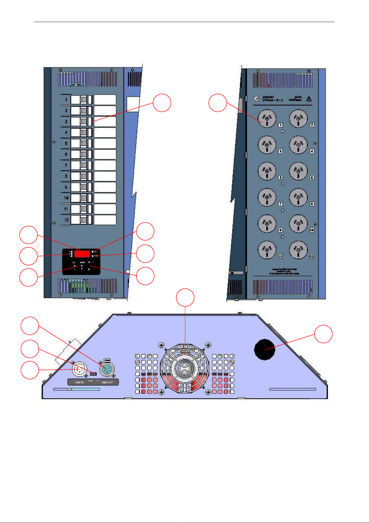
2.1 Panel layout ............................................................................................................ 2-1
3.0 Getting Started..................................................................... 3-1
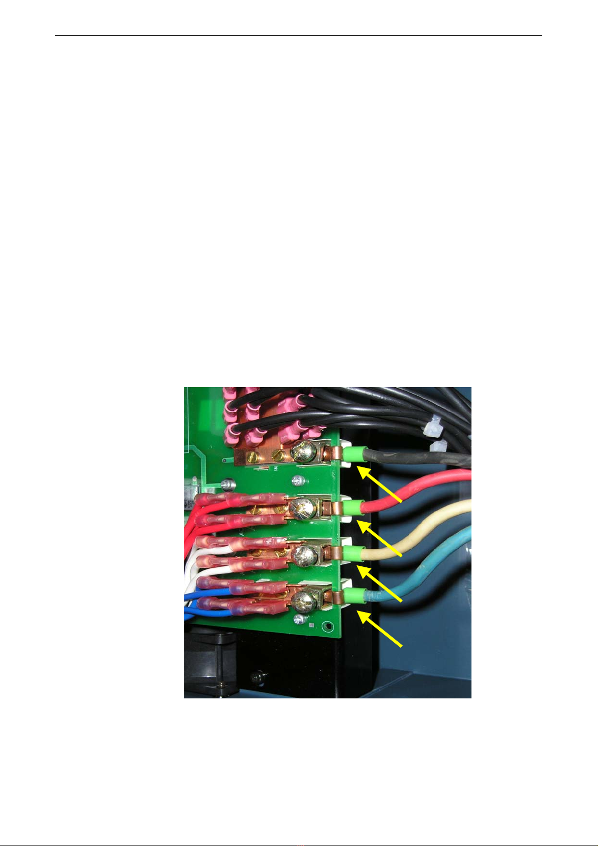
3.1 Connecting power................................................................................................... 3-1
3.2 Setting the mains frequency ................................................................................... 3-2
3.3 Powering up............................................................................................................ 3-2
3.4 Connecting loads .................................................................................................... 3-3
3.5 Connecting DMX-512 input................................................................................... 3-3
3.6 DMX termination ................................................................................................... 3-3
3.7 Power-up sequence ................................................................................................. 3-3
4.0 Dimmer Operation ............................................................... 4-1
4.1 Operating modes..................................................................................................... 4-1
4.1.1 DMX mode.................................................................................................... 4-1
4.1.2 Test mode ...................................................................................................... 4-2
4.1.2.1 Chn .................................................................................................... 4-2
4.1.2.2 PHS ................................................................................................... 4-2
4.1.2.3 CHS................................................................................................... 4-3
4.1.3 Front panel menu structure............................................................................ 4-4
4.2 Fault LED ............................................................................................................... 4-5
5.0 Fault Diagnosis .................................................................... 5-1
5.1 Output protection.................................................................................................... 5-1
5.2 DMX faults ............................................................................................................. 5-1
5.3 Phase fault indication.............................................................................................. 5-2
5.4 Thermal protection ................................................................................................. 5-2
5.5 Over-voltage ........................................................................................................... 5-2
5.6 Fault finding guide.................................................................................................. 5-3
6.0 Installation............................................................................ 6-4
6.1 Dimmer ventilation................................................................................................. 6-5

Contents iv
WMX SERIES DIMMER OPERATING MANUAL
6.2 Wall mounting dimmers - In racks ......................................................................... 6-6
6.3 Wall mounting dimmers - Flush to wall................................................................. 6-7
6.4 Wall mounting dimmers - Straddling cable trays................................................... 6-8
6.5 Wall mounting dimmers - Conduit cable entry ...................................................... 6-9
6.6 Mounting the dimmer to the bracket .................................................................... 6-10
7.0 Maintenance ......................................................................... 7-1
8.0 Technical Data and Specifications..................................... 8-1
8.1 DMX connector pin-outs ........................................................................................ 8-2
8.2 Mains wiring colour codes ..................................................................................... 8-2

Introduction 1-1
WMX SERIES DIMMER OPERATING MANUAL
1.0 Introduction
The JANDS WMX is a high quality, rugged, 12 channel, 2.4kVA per channel
(10A/240V) dimmer rack specifically designed for contracting / theatre applications.
A separate wall bracket simplifies the installation process. It allows cabling to be routed
to the dimmer location prior to the installation of the actual dimmer units, providing the
contractor with the ability to fit off the dimmers when the site is secure.
An optional extended wall mounting bracket, provides the end user with an economical
and compact method of routing cable duct behind the dimmer rack.
Features
• 12 x 2.4KW dimming channels
• DMX-512 digital control protocol
• DMX terminating switch
• Suitable for permanent installations
• Soft turn on characteristic
• Low acoustic/electrical noise
• Toroidal output chokes
• Circuit breaker protection of output devices
• Three mains phase indicator LEDs
• Built in test facilities
• Dimmer curve set for linear relationship between the control input and output power
• Compensation for fluctuations in the mains supply voltage and minimises the effect
of superimposed control tones, ensuring a constant light output and increased lamp
life
• May be rack mounted or attached to a wall by means of supplied mounting bracket
• Microprocessor control
• Temperature controlled cooling fan
• Temperature monitor and thermal cut-out
• Dimmer will hold last DMX value should control data be interrupted
• 50/60Hz operation

Equipment Description 2-1
WMX SERIES DIMMER OPERATING MANUAL
2.0 Equipment Description
Figure 2.1: (Clockwise From Top Left) Control/Breaker Panel, Socket Outlet Panel, Bottom Panel
2.1 Panel layout
1. CHANNEL OUTPUT SOCKETS: The twelve output sockets are each rated at 10
amps.
2. CHANNEL CIRCUIT BREAKERS: If a breaker trips during use ensure the fault
has been cleared before resetting.
12
7
6
3
4
8
5
12
10
11
9
13

Equipment Description 2-2
WMX SERIES DIMMER OPERATING MANUAL
3. UP/DOWN SELECT BUTTONS: These buttons select the DMX start channel and
various test functions.
4. EXIT AND MENU/CONFIRM BUTTONS: These buttons are used to navigate
through the test menu levels and set DMX address.
5. 3-DIGIT DISPLAY: Indicates currently selected DMX start channel and various
test function options.
6. DMX LED: A green LED indicates the presence of DMX signals when in DMX
mode. If there is no DMX signal, the LED will flash at a rate of approximately 2
seconds on - 2 seconds off.
7. FAULT LED: A red LED flashes in the presence of a fault. In normal operation this
LED should be off.
8. PHASE LEDs: Three blue LEDs (one for each phase) indicate that the three phase
mains supply is available.
9. DMX IN SOCKET: Standard 5-pin AXR connector accepts DMX-512 signals from
controller.
10.DMX LOOP SOCKET: Standard 5-pin AXR connector links the DMX-512 signals
to other dimmers or devices.
11.TERMINATE SWITCH: In the right hand Loop position it links the male IN
socket to the female LOOP socket, continuing the DMX signal to other devices. The
left hand Terminate position is used to terminate the DMX signal if this unit is the
last device in DMX chain.
12.CABLE ENTRY: Removal of the hole plug provides access for a 32mm cable
gland. This cover should remain in place for safety reasons unless using the hole for
cable access.
13.AIR INTAKE: This is the main entry point for air cooling of the dimmer. DO NOT
obstruct this entry and keep it free of dust.

Getting Started 3-1
WMX SERIES DIMMER OPERATING MANUAL
3.0 Getting Started
The WMX would normally be wall mounted before any wiring is terminated. Refer to
section 6.0 Installation for details.
3.1 Connecting power
The WMX dimmer is supplied with 4 rising clamp terminals for the connection of
incoming mains power and a ring star connector for the incoming protective earth wire.
To gain access to the input terminals, it is first necessary to remove the front cover that
wraps around to the control panel and circuit breaker side of the dimmer, followed by
the socket outlet panel. Note: The earth wire can be removed from the front panel by
means of a spade connector on the bottom right corner of the panel, allowing the panel
to be placed to one side while working on the dimmer.
Connect the incoming mains power cables to the rising clamp terminals on the lower
right side of the main circuit board. The three phase conductors shall be connected to
the terminals marked Active A1, Active A2 and Active A3. The neutral conductor shall
be connected to the terminal marked Neutral. It is important that the ends of the
conductors go under the circuit board between the flat of the rising clamp and the
copper bracket on the circuit board. Do not screw down directly onto the wire.
Figure 3.1 Mains Power Termination
To connect the earth wire, strip the insulation back approximately 35mm, wrap the bare
end around the supplied star lug and crimp with pliers (Figure 3.2). Secure crimped
earth wire to stud using supplied washers and nut (Figure 3.3).
Active A3
Active A2
Active A1
Neutral

Getting Started 3-2
WMX SERIES DIMMER OPERATING MANUAL
Figure 3.2: Crimping Of Star Lug For Incoming Protective Earth
Figure 3.3: Termination Of Protective Incoming Earth Conductor To Earth Busbar
If the frequency needs to be changed to 60Hz, refer to section 3.2 Setting the mains
frequency before continuing. Check that the securing screw has been inserted through
the lower right corner of the chassis into the wall mounting base plate (refer to section
6.6 Mounting the dimmer to the bracket for more information).
Replace the cover panels, starting with the socket outlet panel. When replacing the
covers, check to make sure that the two earth straps are connected to the chassis and the
front cover for the control and circuit breakers. If not, push connectors onto the tabs
marked with the earth symbol and the replace covers.
3.2 Setting the mains frequency
The WMX can be configured to run from either 50Hz or 60Hz mains power - as
supplied from the factory it is configured for 50Hz. To change the dimmer to 60Hz,
change the three jumpers to “60Hz” as per Figure 3.4.
Figure 3.4: 60Hz Jumper Locations
3.3 Powering up
Turn on the power and check that the three PHASE indicator LEDs are on before
connecting any loads. If the PHASE LEDs indicate a fault condition (refer to section 5.3
Phase fault indication), power down and remedy the fault before trying again.
Nu
t
Washe
r
Lug
Washe
r

Getting Started 3-3
WMX SERIES DIMMER OPERATING MANUAL
If all is well, power down and connect loads.
3.4 Connecting loads
The standard output connectors are twelve 10 amp Australian sockets (Export models
may differ from these configurations). Ensure any plugs are pushed firmly into their
sockets and/or all screw terminals are tight.
The WMX will drive most incandescent loads as well as some downlight transformers
(suitable for leading edge dimmer control), fans, and dimmable fluorescent tubes. The
load should be greater than the specified minimum (refer to section 8.0 Technical Data
and Specifications).
3.5 Connecting DMX-512 input
The input signal to the dimmer should conform to the AMERICAN NATIONAL
STANDARD (ANSI) E1.11-2004 ENTERTAINMENT TECHNOLOGY USITT DMX-
512-A specification. Plug the DMX signal to the “DMX IN” socket. The DMX signal
may be daisy-chained to the next dimmer via the LOOP connector.
When power is on the DMX LED indicates the presence of DMX signals.
The DMX receiver input is protected against extreme over-voltages across any input
pins and from any input to chassis. The “terminating” resistor is not protected against
over-voltages.
3.6 DMX termination
In any DMX-512 system the signal should be terminated at the last dimmer or receiver
in the chain, and the WMX can provide this function. To terminate the DMX signal, set
the front panel slide switch from LOOP to the Terminate position. Note that in this
position no signal is present at the LOOP connector.
3.7 Power-up sequence
When powering up lighting systems, the following sequence should be used:
1. First the control desk;
2. Then any softpatches and/or DMX receivers;
3. Finally the dimmers, preferably one at a time starting from the first dimmer rack in
the DMX loop.
This procedure minimises the risk of producing the lighting equivalent of an audio
“thump” and prevents damage to lamps, dimmers, and other controlled devices.
Use the reverse procedure when powering down.

Dimmer Operation 4-1
WMX SERIES DIMMER OPERATING MANUAL
4.0 Dimmer Operation
This section assumes the dimmer has been correctly connected to three phase power and
a source of DMX-512 control signal.
Figure 4.1: Control Panel Layout
o Pressing “Menu/" at any time moves up menu level or confirms a new setting.
o Pressing the “Exit/C” button at any time moves back a menu level with no setting
change.
o When adjusting a setting, the display will flash briefly once per second for three
seconds. If the “Menu/" button is pressed within that three seconds, the new value is
retained and subsequently takes effect. If no button is pressed within that 3 seconds, or
if the “Exit/C” button is pressed within 3 seconds, the setting reverts to the previous
value.
4.1 Operating modes
The WMX has two operating modes:
1. DMX mode: the dimmer is controlled from an external DMX-512 control
console,
2. Test mode: the dimmer is controlled by the internal microprocessor and the
front panel buttons.
4.1.1 DMX mode
In this mode, the “+” and “−” buttons are used to select which bank of 12 channels
(from the 43 possible DMX-512 banks) will control the WMX.
By default the display shows the DMX start channel. The start channel can only be
changed in steps of 12. Pressing the “+” or “−” button results in the display increasing
or decreasing by one bank of 12 channels. Eg. 1, 13, 25, etc.
For example, if DMX Channels 25 to 36 are desired, set the start channel to “25”.
WMX Channel #1 is now DMX Channel #25. A WMX with this setting ignores DMX
Channels 1 to 24 and 37 to 512, and only decodes Channels 25 to 36 as its dimmer
information.
Pressing and holding the “+” or “−” button results in the display changing by one bank,
and after 0.5 seconds it will start changing automatically at a fast rate.

Dimmer Operation 4-2
WMX SERIES DIMMER OPERATING MANUAL
The display will halt at 505 in the up direction and at 1 in the down direction, but if the
button is released and pressed again the menu will wrap around from 505 to 1 (or from
1 to 505 in the other direction).
Once selected, the start channel is retained in memory if the power is switched off.
4.1.2 Test mode
In this mode, the WMX’s internal controller is used to drive the selected dimmer
channels. No DMX control is necessary, but a control signal may be left connected if
desired.
Pressing the “Menu/” button displays the first menu item. The menu items are listed
in Table 4.1.
Display Description
Turn selected Channel on full
Turn Phase channels on at set level
Turn on all channels sequentially at set rate
Table 4.1: Menu Items
Pressing the “−” button when the display shows Chn changes it to CHS; pressing the
“+” button when the display shows CHS changes it to Chn,ie. the menu wraps around.
Pressing the “Exit/C” button returns the dimmer to normal operation, displaying the
previously set DMX start channel.
4.1.2.1 Chn
Pressing “Menu/” while Chn is displayed moves into the Channel Test menu. The
display shows the last channel tested (C 1 … C12) and immediately turns it on full.
The “+” and “−” buttons may be used to select a different channel. The channel is
output live and there is no need to press “Menu/”. The display (and output) remains in
that state until the “Exit/C” button is pressed, even if power is disconnected; ie. when
power is restored the dimmer will continue to drive the selected channel to full.
Pressing the “−” button when the display shows C 1 changes it to C12. Pressing the
“+” button when the display shows C12 changes it to C 1; ie. the menu wraps around.
When “Exit/C” is pressed, the dimmer returns to the menu displaying flashing Chn. If
no button is pressed within 3 seconds the dimmer returns to normal operation,
displaying the previously set DMX start channel.
4.1.2.2 PHS
Pressing “Menu/” while PHS is displayed moves into the Phase Test menu, and the
display shows the last phase tested (A, B, C, or ALL). Pressing “+” or “−” and
then “Menu/” selects a phase to test. That phase is indicated on the display with a top,
middle, or lower horizontal bar in the left-most display digit, signifying phases A, B and
C respectively. The display initially shows a phase level of 0. All channels fed from the
selected phase will be tested simultaneously.
ie. Phase A = Channels 1-4, Phase B = Channels 5-8, Phase C = Channels 9-12.

Dimmer Operation 4-3
WMX SERIES DIMMER OPERATING MANUAL
The “+” and “−” buttons are used to select a different level in 20% increments, ie. 20,
40, 60, 80, FL (100). Refer to table 4.2 for the display output in each state.
Output
Level
Phase A
Display
Phase B
Display
Phase C
Display
ALL Phases
Display
0%
20%
40%
60%
80%
100%
Table 4.2: Display Data To Output Level Relationship
The output is live and there is no need to press “Menu/”. The display (and output)
remains in its current state until the “Exit/C” button is pressed, even if power is
disconnected. ie. when power is restored the dimmer will continue to drive the selected
phase to the same level.
When “Exit/C” is pressed, the dimmer returns to the menu displaying flashing A, B,
C or ALL. If no button is pressed within 3 seconds the dimmer returns to normal
operation, displaying the previously set DMX start channel.
4.1.2.3 CHS
Pressing “Menu/” while CHS is displayed moves into the Chase menu, where the
display shows the last chase speed selected (SP1…SP4) and the chaser is immediately
turned on. Each channel from 1 to 12 is sequentially driven to full output and then the
chase sequence keeps repeating.
The “+” or “−” buttons are used to select a chase speed; SP1 is slowest and SP4 is
fastest. The display (and output) remains in its current state until the “Exit/C” button is
pressed, even if power is disconnected. ie when power is restored the dimmer will
continue to run the chase at the selected rate.
When “Exit/C” is pressed, the dimmer returns to the menu displaying flashing CHS. If
no button is pressed within 3 seconds the dimmer returns to normal operation,
displaying the previously set DMX start channel.

Dimmer Operation 4-4
WMX SERIES DIMMER OPERATING MANUAL
4.1.3 Front panel menu structure
CHANNEL TEST
+ -
PHASE A TEST
+ -
CHASE MENU
+ -
DMX ADDRESS
DMX ADDRESS
(Fla
shing
dil)
+ -
(Times out after 3
S)
DMX ADDRESS
TEST MENU
TEST MENU
TEST MENU
PHASE TEST
PHASE TEST
PHASE TEST
PHASE TEST
PHASE B TEST
+ -
A
LL PHASE
TEST
+ -
PHASE C TEST
+ -
Menu
+ -
+ -
+ -
+ -
+ -
+ -
Exit
Menu
Menu
Exit
Exit
Menu
Menu
Exit
Exit
Menu
Menu
Exit
Exit
Menu
Menu
Exit
Figure 4.2: Front Panel Menu Structure

Dimmer Operation 4-5
WMX SERIES DIMMER OPERATING MANUAL
4.2 Fault LED
The Fault LED is used to indicate fault conditions. In normal operation this LED should
not illuminate. When active this LED will either be flashing or on continuously.
1. When the LED is flashing an over-temperature or over-voltage condition is present,
and the dimmer outputs will be off until the over-voltage or over-temperature
condition is removed.
2. When the Fault LED is on continuously, one or more of the following error
conditions have occurred:
• Over-voltage
• Over-temperature
• Serial data errors
• Software failure
The dimmer outputs are active while the Status LED is on continuously.
If the Fault LED is on it may be cleared by pressing the “+” or “−” buttons, or by
switching the dimmer off momentarily.

Installation 5-1
WMX SERIES DIMMER OPERATING MANUAL
5.0 Fault Diagnosis
NOTE
Contact your authorised JANDS Distributor for repairs or servicing.
In Australia refer all repairs to an authorised JANDS service agent or return the
faulty unit in suitable packaging to:
JANDS Service Dept,
Unit 2 / 26 Kent Rd
Mascot NSW 2020
Australia
5.1 Output protection
Each of the twelve output circuits is protected by a 10 Amp fast-acting
thermal/magnetic circuit breaker. These breakers are designed to pass the rated current,
but will disconnect the output circuit for any overload condition (the larger the
overload, the quicker the disconnection).
NOTE: 3-pin GPO outlet sockets are rated at 10 Amps. Dimmer channels should
not be loaded beyond the socket capacity.
The breakers protect the dimmer’s output devices from short-circuit loads, faulty wiring
looms and save on expensive dimmer repairs. A tripped circuit breaker indicates a load
fault that requires immediate attention.
If a short-circuit lamp or output cable is plugged into the dimmer, the breaker will trip
to disconnect the fault from the dimmer. In nearly all circumstances, this is quick
enough to prevent damage to the output devices.
In some circumstances however, a triac failure may be experienced, although these
devices are usually quite reliable and robust. If a triac does fail, it will either turn a
channel on to full (triac short-circuit), or turn it off (triac open-circuit). If a triac fault
should occur, that channel may be isolated by manually tripping that channel’s circuit
breaker.
These breakers have been specified for electrical protection, reliability and safety. They
will allow repeated turn-on surges to cold lamps without failure, while still protecting
the triacs. The breakers will interrupt large short-circuit fault currents without damage.
5.2 DMX faults
The WMX dimmer features an “Output Hold” facility that “remembers” the last
received DMX message. In the event of a cable being unplugged or severed, the WMX
dimmer rack will continue to output the “Held” DMX levels until a new DMX message
is provided. If no new data is received within 10 minutes the outputs are driven to 0.
The DMX LED will flash slowly if the DMX signal is removed.
Note that control consoles, when powered down, may transmit spurious DMX data
which can unintentionally cause dimmer channels to turn on. Disconnect mains power
when not in use.

Installation 5-2
WMX SERIES DIMMER OPERATING MANUAL
The DMX receiver input is protected against extreme over-voltages across any input
pins and from any input to chassis. The “terminating” resistor is not protected against
over-voltages.
5.3 Phase fault indication
The three blue PHASE LEDs show when all three power input phases are present.
WARNING
IF ONE OR MORE PHASE LEDS IS OFF, IMMEDIATELY DISCONNECT
POWER TO THE DIMMER AND CHECK THE MAINS SUPPLY AND
WIRING BEFORE RE-CONNECTING POWER TO THE DIMMER.
Although the dimmer will survive most power supply faults, indications of unusual or
potentially dangerous power conditions should never be ignored.
5.4 Thermal protection
The WMX dimmer features temperature-controlled fan cooling. As the internal
temperature of the dimmer increases, the fan speed also increases.
The internal heatsink temperature is constantly monitored by the dimmer. If the heatsink
temperature rises above the specified maximum, the dimmer will automatically shut
down the output drive. The fan will continue to cool the heatsink during the shut down
period.
The electronic shutdown is backed up by a buried cutout, which shuts down power to all
electronics other than the cooling fan should the temperature continue to rise.
Even though the WMX is a fan-cooled dimmer, it is very important that adequate
ventilation is provided when in use, particularly around the top and bottom of the
chassis. If air circulation to the air vents is blocked and/or the ambient air temperature is
too high, the dimmer will shut down and the status LED will flash until the temperature
is reduced.
Refer to section 6.1 Dimmer ventilation regarding WMX dimmer ventilation
requirements.
5.5 Over-voltage
The WMX incorporates an over-voltage cutout that constantly monitors the incoming
mains voltage. If the mains voltage rises above the specified maximum the dimmer will
shut down and the status LED will flash until the over-voltage condition is removed.

Installation 5-3
WMX SERIES DIMMER OPERATING MANUAL
5.6 Fault finding guide
FAULT SYMPTOM POSSIBLE CAUSE REMEDY
Breaker trips when desk channel
flashed to full or near full
Large incandescent load
Excessive load
Use console preheat facility
Reduce channel loading
Breaker trips after prolonged
operation
Excessive load
Lamp or wiring fault
Reduce channel loading
Check lamps and wiring
Breaker trips immediately when
channel is driven
Output short
Triac short
Check lamps and wiring
Factory service
One channel flickers when dimmed
Same load flickers on another
Channel
DMX source problem
Faulty dimmer channel
Insufficient or very inductive load
Softpatch another console fader
Service console
Factory service
Connect >100W incandescent
lamp in parallel
Radio interference Faulty EMC filtering Factory service
All Channels flicker when dimmed Incorrect DMX protocol / wiring
Unterminated DMX line
Mains control tones exceed limits
Replace DMX source / wiring
Set Terminate switch on last
DMX receiver to TERM
Contact factory
DMX LED flickers Faulty DMX wiring/connections
Faulty console
Faulty dimmer rack
Repair
Repair
Factory service
Fault LED flashing Over-voltage
Over-temperature
Check mains connection/supply
Improve dimmer cooling
Fault LED on continuously Recent over-voltage
Recent over-temperature
DMX control errors
Software failure
Check mains connection/supply
Improve dimmer cooling
Check DMX wiring, console
Factory service
No signal at DMX Loop output Terminate switch set to TERM Set Terminate switch to LOOP
Figure 5.1: Fault finding guide

Installation 6-4
WMX SERIES DIMMER OPERATING MANUAL
6.0 Installation
The WMX dimmer is designed for use in fixed installations - the dimmer is supplied
with a wall-mounting bracket. This bracket enables the WMX to be mounted in one of
the following arrangements:
• The dimmer may be mounted in a 19 inch equipment rack (11RU of rack space
required)
• The dimmer may be mounted flush to a wall with the cabling coming through the
wall
An optional extended mounting bracket allows the following mounting options:
• The dimmer may be mounted proud of a wall for use with surface cable conduit. The
conduit may run either horizontally or vertically
• The dimmer may be mounted straddling a vertical cable tray up to 420mm wide and
75mm deep

Installation 6-5
WMX SERIES DIMMER OPERATING MANUAL
6.1 Dimmer ventilation
The WMX dimmers are cooled by a temperature controlled fan. The air intake is at the
bottom, and exhausts through slots at the top and top-front.
The WMX dimmers are intended for wall mounting in unenclosed spaces. Multiple
dimmer arrays should be spaced at least 100mm apart vertically, and no more than
three dimmers high, to avoid excessive heating of the top dimmer. Dimmers should be
spaced at least 50mm horizontally.
Dimmers should be mounted at least 300mm from the floor to avoid excessive ingress
of dust and fluff, or as dictated by local building statutes. Dimmers must be mounted at
least 150mm below ceilings or shelves for adequate ventilation.
Mounting within unventilated cupboards is not recommended. If the dimmers are
mounted within cupboards, allow at least 150mm above and below the dimmer, and at
least 100mm at each side and the front of the dimmer. In addition, the cupboard must be
vented with at least 400 cm2 (eg 40cm x 10cm) per dimmer at the top and bottom of the
cupboard. Additional venting area will serve to further reduce internal dimmer
temperatures and will enhance the dimmer’s reliability.
Figure 6.1: Spacing Of Wall Mounting Dimmers
Table of contents
Other Jands Dimmer manuals