Section 2. System Description
Levolor II by Jandy Model K-2000 is a computer-
controlled device that detects low and high water
conditions.
This model can be used in any situation where a
consistent liquid level is desired and a high and low
level situation can be detected and acted upon, such as
a Vanishing Edge pool. It automatically lls the pool
when the water level is too low and stops lling the pool
when the water level is normal
The K-2000 Kit contains a sensor, remote sensor
housing, control box, and solenoid valve. For details
about the materials in the kit and a list of additional
materials needed to install the K-2000 kit, refer to
Section 3.1, Materials and Tools.
Sensor
The sensor has three (3) probes: one (1) short probe
to measure the high water level, one (1) long probe to
measure the minimum operating level of the water, and
one (1) long common probe. The long probes come in
4", 18"and 30"lengths.
The sensor is a slip-type sensor that glues to a 1"
coupling.
Depending on the kit, the sensor comes with 50 to
500 feet of wire at the top and three (3) stainless steel
contacts at the bottom. The excess wire should be cut
off after you have completed the installation.
Control Box
The control box has ve (5) LED lights. They are:
- Power
- Sensor
- Fill
- High Water Sensor
- High Water Pump
For details about the functions of the lights, refer to
Section 4.1, Controller Lights.
The control box is factory wired for 220 volt operation,
but can optionally be rewired for 110 volt operation. See
Section 3.3, Changing Wiring for 110 Volt Operation.
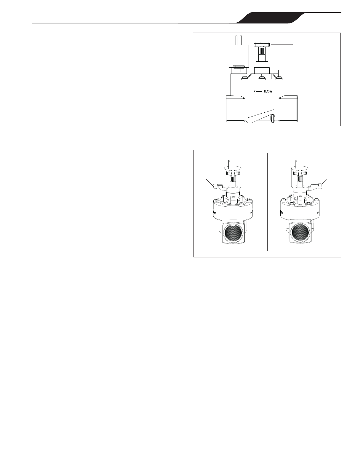
Valve
The K-2000 requires one (1) 24VAC solenoid valve.
The Jandy-supplied valve (PN SOL100) has a pressure
rating that cannot exceed 125 PSI.
2.1 ElectricalSpecications
Input: 110VAC, 50/60 HZ, 0.5 AMPS
220VAC, 50/60 HZ, 0.5 AMPS
Valve Output: 24VAC@ 1 AMP
Relay Output: 24VDC@ 1 AMP
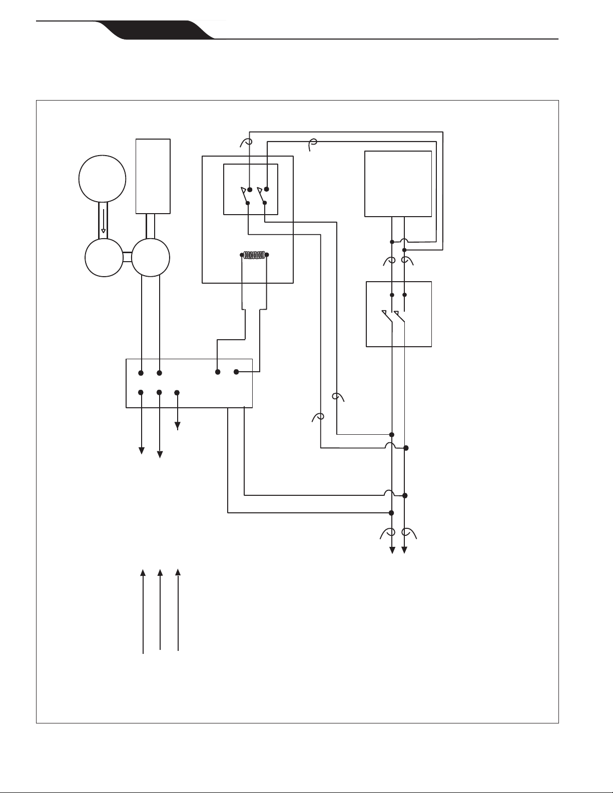
CAUTION
Model K-2000 is factory wired for 220VAC
service. Ifavailableelectricalserviceis
110VAC,thepowersupplywiringmustbe
changedtooperateon110VACasshownin
Figures3and4.
Page 5
ENGLISH
Jandy Pro Series Levolor®II Electronic Water Leveler
Models K-2000 |Installation and Operation Manual