Jandy Air Energy AE-Ti User manual

Installation and
Operation Manual
Installation and Operation Data
DANGER
RISK OF ELECTRICAL SHOCK OR ELECTROCUTION. The electrical supply to this product
must be installed by a licensed or certified electrician in accordance with applicable national and
local codes and ordinances. Improper installation will create an electrical hazard, which could
result in death or serious injury to pool or spa users, installers, or others due to electrical shock,
and may also cause damage to property. Read and follow the specific instructions inside this
manual.
Air Energy™
Heat Pumps
Model AE-Ti
H3005600B


Page 1
Table of Contents
Section 1. General Information ..................5
1.1 Introduction......................................................... 5
1.2 Consumer Information and Safety...................... 5
1.2.1 Spa/Hot Tub Safety Rules............................5
1.2.2 Swimming Pool Energy Saving Tips ............ 6
1.3 Warranty ............................................................. 6
1.4 Codes and Standards......................................... 6
1.5 Technical Assistance........................................... 7
1.6 Materials Needed For Installation....................... 7
1.6.1 Materials for All Installations ........................ 7
1.6.2 Recommended Materials for Installations.... 7
1.7 Specifications...................................................... 7
1.7.1 General Specifications................................. 7
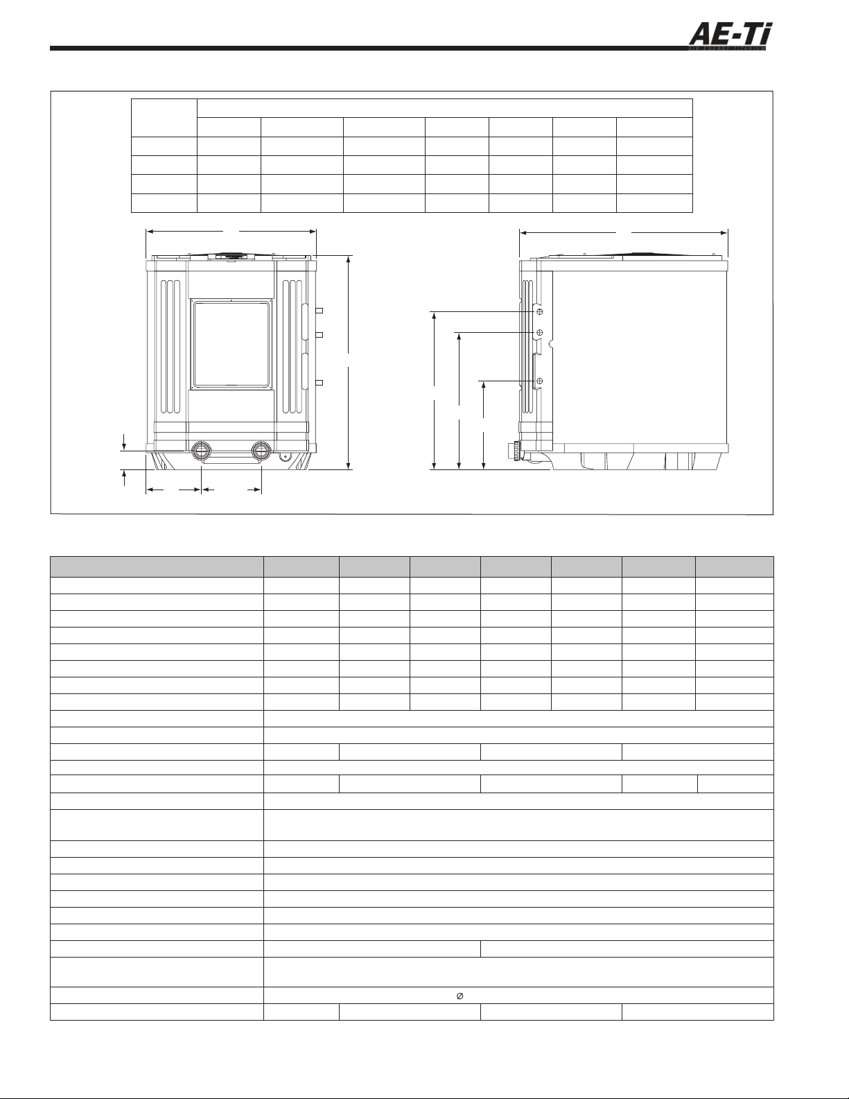
1.7.2 Dimensions .................................................. 7
1.7.3 Technical Specifications............................... 8
Section 2. Installation Instructions ...........9
2.1 General Information ............................................ 9
2.2 Location Requirements....................................... 9
2.2.1 Introduction .................................................. 9
2.2.2 Clearances................................................... 9
2.2.3 Equipment Pad ............................................ 9
2.2.4 Indoor Installations..................................... 10
2.2.4.1 Condensation and Drainage ................ 10
2.2.5 Outdoor Installations.................................. 10
2.2.5.1 Lawn Sprinklers ................................... 10
2.2.5.2 Roof Run-off......................................... 11
Section 3. Water Connections .................11
3.1 Plumbing Layout .............................................. 11
3.2 Water Connections at Heat Pump .................... 11
3.3 Check Valve Installation.................................... 11
3.4 Automatic Flow Control Valve........................... 11
3.5 Filtration System Layouts ................................. 11
3.5.1 Shared Filtration System............................ 11
3.5.2 Independent Filtration System ................... 11
3.6 Multiple Unit Installation.................................... 13
3.6.1 Heat Pump and Heater Combination......... 13
3.6.2 Multiple Heat Pump Connections............... 13
Section 4. Electrical Connections............13
4.1 General Information .......................................... 16
4.2 Main Power....................................................... 16
4.3 Bonding (Earthing)............................................ 16
4.4 Pump Connection (Maintain Temp Feature) ..... 16
4.5 Optional Remote Controls ................................ 16
4.5.1 Connection to a Remote Pool-Off-Spa
Selector (3-Wire Connection)..................... 16
4.5.1.1 Install the Remote Pool-Off-Spa
Selector................................................ 16
4.5.1.2 Configure the Control Panel ................ 21
4.5.2 Two-Wire Connection to an AquaLink®RS
or TSTAT.................................................... 21
4.5.2.1 Configure the AquaLink®RS Control
System................................................. 21
4.5.2.2 Install the Remote TSTAT or
AquaLink®RS ...................................... 21
4.5.2.3 Configure the Control Panel ................ 21
4.5.3 Four-Wire Connections to AquaLink®
RS 485 Communication............................. 22
4.5.4 Connection to a Secondary
User Interface ............................................ 23
Section 5. Operation..................................23
5.1 Initial Start-up Precautions................................ 23
5.2 Operating the Controller ................................... 24
5.2.1 Off Mode .................................................... 24
5.2.2 Pool Mode - (Normal Heat)........................ 24
5.2.3 Pool Mode - (Optional Maintain Heat)........ 24
5.2.4 Spa Mode - (Normal Heat)......................... 24
5.2.5 Spa Mode - (Optional Maintain Heat) ........ 24
5.3 Operating Features of Units with
Optional Chiller ................................................. 25
5.3.1 Pool Mode - (Normal Chill)......................... 25
5.3.2 Pool Mode - (Optional Maintain Chill) ........ 25
5.3.3 Spa Mode - (Optional Maintain Chill)......... 25
5.4 User Setup Options .......................................... 25
5.4.1 Language Setup......................................... 25
5.4.2 Temperature Scale Setup ..........................26
5.4.3 Spa Timer Setup ........................................ 26
5.4.4 Display Light Setup.................................... 26
5.5 Set Point Lockout.............................................. 26
5.6 Water Pressure Switch Adjustment................... 26
Section 6. General Maintenance .............27
6.1 Water Chemistry ............................................... 27
6.2 Winterizing........................................................ 27
6.3 Spring Start-Up ................................................. 28
6.4 Inspection and Service ..................................... 28
6.4.1 Owner Inspection....................................... 28
6.4.2 Professional Inspection.............................. 29
Section 7. Professional Maintenance
and Service ..............................29
7.1 Heat Pump Design............................................ 29
7.2 Heat Pump Components and
Their Operation................................................. 30
7.3 Service Setup Options...................................... 30
7.3.1 Maintain Temperature ................................ 30
7.3.2 Maintain Temperature Delay ...................... 30
7.3.3 Remote ...................................................... 30
7.3.4 Defrost Selection........................................ 30
7.3.5 Test Mode .................................................. 30

Page 2
Figures and Tables
Figure 1. AE-Ti Heat Pump Dimensions ...................8
Figure 2. Standard Plumbing Layout.......................10
Figure 3. Shared Filtration System..........................12
Figure 4. Dual Pump System (Independent
Filtration Systems Sharing a
Heat Pump)..............................................12
Figure 5. Plumbing For Heating System
Combinations ...........................................13
Figure 6. Two Heat Pump Plumbing Layout............14
Figure 7. Four Heat Pump Plumbing Layout...........14
Figure 8. Six Heat Pump Plumbing Layout .............15
Figure 9. Eight Heat Pump Plumbing Layout
(Dual Headers).........................................15
Figure 10. AE-Ti Single-Phase Electrical Supply
Wiring Diagram ........................................17
Figure 11. AE-Ti 3-Phase Electrical Supply
Wiring Diagram ........................................18
Figure 12. Electrical Wiring Diagram Symbol
Definitions ................................................19
Figure 13. Example of wiring to the Time Clock for
enabling the “MAINTAIN TEMP” feature..20
Figure 14. AE-Ti Heat Pump Front View...................20
Figure 15a. Remote Pool-Off-Spa Connection
(3-Wire Connection).................................21
Figure 15b. AquaLink RS or Remote TSTAT
Connection (2-Wire Connection)..............21
Figure 16. AquaLink RS to AE-Ti Heat
Pump/Chiller Wiring .................................22
Figure 17. AE-Ti Heat Pump Connection to
Power Center ...........................................23
Figure 18. Main Control Panel ..................................24
Figure 19. Winterizing the AE-Ti Heat Pump.............29
Figure 20. Heat Pump Operation Overview ..............29
Figure 21. Air Energy™ AE-Ti Heat Pump
Exploded View ........................................37
Table 1. Recommended Minimum Cross-Sectional
Area of Conductors of Supply Wiring.........7
Table 2. AE-Ti Heat Pump Technical
Specifications.............................................8
Table 3. Heat Pump Clearances..............................9
Table 4. Optimal Water Chemistry Ranges............28
Table 5. Heat Pump Troubleshooting Guide..........33
Table 6. Heat Pump Fault Diagnostic Condition ....34
Table 7. Resistance - Temperature,
10,000 Ohm “J” ........................................35
Table 8. Reference Technical Data for
Troubleshooting .......................................35
Table of Contents (Continued)
7.3.6 Load Defaults............................................. 31
7.3.7 Coil Temperature Calibration ..................... 31
7.3.8 Water Temperature Calibration .................. 31
7.3.9 Water Temperature Differential .................. 31
7.3.10 Delay On Make .......................................... 32
7.3.11 Last Fault ................................................... 32
Section 8. Troubleshooting ......................33
8.1 Troubleshooting Guide...................................... 33
8.2 Diagnostics ....................................................... 34
Section 9. Replacement Parts ..................36
9.1 Ordering Information......................................... 36
9.2 Air Energy™AE-Ti Heat Pumps Parts List....... 36
9.3 Air Energy™AE-Ti Heat Pump
Exploded View .................................................. 37


Page 5
1.2 Consumer Information and Safety
The AE-Ti series of heat pumps are designed
and manufactured to provide many years of safe
and reliable service when installed, operated and
maintained according to the information in this manual
and the installation codes referred to in later sections.
Throughout the manual, safety warnings and cautions
are identified by the “ “ symbol. Be sure to read and
comply with all of the warnings and cautions.
1.2.1 Spa/Hot Tub Safety Rules
WARNING
The U.S. Consumer Product Safety Commission
warns that elevated water temperature can
be hazardous. Consult heater operation and
installation instructions for water temperature
guidelines before setting temperature.
WARNING
The following “Safety Rules for Hot Tubs,”
recommended by the U.S. Consumer Product
Safety Commission, should be observed when
using the spa.
1. Spa or hot tub water temperature should never
exceed 40°C (104°F). One hundred degrees
Fahrenheit 38°C (100°F) is considered safe for a
healthy adult. Special caution is recommended for
young children.
2. The drinking of alcoholic beverages before or
during spa or hot tub use can cause drowsiness
which could lead to unconsciousness, and
subsequently result in drowning.
3. Pregnant women take note! Soaking in water
above 38.5°C (102°F) can cause fetal damage
during the first three months of pregnancy (which
could result in the birth of a brain-damaged or
deformed child). If pregnant women are going
to use a spa or hot tub, they should make sure
the water temperature is below 38°C (100°F)
maximum.
4. The water temperature should always be checked
with an accurate thermometer before entering a
spa or hot tub. Temperature controls may vary by
as much as 1C°/1F°.
5. Persons with a medical history of heart disease,
diabetes, circulatory or blood pressure problems
should consult their physician before using a hot
tub or spa.
Section 1. General Information
1.1 Introduction
This manual provides installation and operation
instructions for the Air Energy™AE-Ti models of
Heat Pumps. Read these installation and operation
instructions completely before proceeding with the
installation. Consult Air Energy™with any questions
regarding this equipment. To obtain additional copies of
this manual contact us at 1-707-776-8200 ext. 237. The
following is the address information for Air Energy™:
2735 NW 63rd Court.
Fort Lauderdale, FL USA 33309
The AE-Ti heat pump gets electrical power from
an external source and provides a dual electronic
thermostat control system for pool/spa combinations or
preheat convenience.
This heat pump is specifically designed for
heating fresh water swimming pools and spas. Do not
use it as a general service heater. Consult your dealer
for the appropriate Air Energy™products for these
applications.
NOTE “Fresh water swimming pools and spas” include
systems that utilize saltwater chlorine generator
units, such as the AquaPure Electronic Chlorine
Generator. Please ensure that the salt content
of the pool/spa does not exceed 4000 ppm and
water flow rate is within 113 - 475 lpm.
ATTENTION
Installation and service must be performed
by a qualified installer or service agency.
To the Installer: After installation, these
instructions must be given to
the homeowner or left on or
near the heat pump.
To the User: This manual contains
important information that
will help you in operating and
maintaining this heat pump.
Please retain it for future
reference.

Page 6
6. Persons taking any medication which induces
drowsiness (e.g., tranquilizers, antihistamines, or
anticoagulants) should not use spas or hot tubs.
7. Prolonged immersion in hot water can induce
hyperthermia.
Hyperthermia occurs when the internal body
temperature reaches a level several degrees above the
normal body temperature of 37°C (98.6°F). Symptoms
include dizziness, fainting, drowsiness, lethargy, and an
increase in the internal body temperature. The effects of
hyperthermia include:
• Lack of awareness of impending hazard
• Failure to perceive heat
• Failure to recognize need to leave spa
• Physical inability to leave spa
• Fetal damage in pregnant women
• Unconsciousness resulting in a danger of
drowning
1.2.2 Swimming Pool Energy Saving Tips
It is important to note that a heat pump will not
heat a pool as fast as a large gas or electric pool heater.
If the pool water is allowed to cool significantly, it may
take several days to return to the desired swimming
temperature. For weekend use, it is more economical
to maintain the pool water temperature at or near your
desired swimming temperature. If you do not plan to
use your pool for a prolonged period, then you might
choose to turn the heat pump completely off or decrease
the temperature setting of the control several degrees to
minimize energy consumption.
Air Energy™offers the following
recommendations to help conserve energy and minimize
the cost of operating your heat pump without sacrificing
comfort.
1. The American Red Cross recommends a maximum
water temperature of 25°C (78°F). Use an accurate
pool thermometer. A difference of 2°C (4°F),
between 25°C (78°F) and 28°C (82°F), will
significantly increase energy consumption.
2. Carefully monitor the water temperature of your
pool in the summertime. You can reduce heat
pump usage due to warmer air temperatures.
3. During the winter or when on vacation for longer
than a week, turn off the heat pump.
4. Find the proper setting on the heat pump
temperature control and use the Set Point Lockout
function or lock the cover on the heat pump
controller to discourage further adjustments.
5. Set the pump time clock to start the pump no
earlier than 6:00 AM during the pool heating
season. This is the time when nightly heat loss
balances.
6. Where possible, shelter the pool from prevailing
winds with well-trimmed hedges or other
landscaping, cabanas, or fencing.
7. Always use a pool cover when practical. Besides
providing a valuable safety feature, a pool cover
will reduce heat loss, conserve chemicals, and
reduce the load on filter systems.
1.3 Warranty
The Air Energy™AE-Ti heat pump is sold with
a limited factory warranty. Details are specified on the
back cover of this manual.
Make all warranty claims to an authorized Air
Energy™dealer or directly to the factory. Claims
must include the heat pump serial number and model
(this information can be found on the rating plate),
installation date, and name of the installer. Shipping
costs are not included in the warranty coverage.
The warranty does not cover damage caused by
improper assembly, installation, operation, winterizing,
field modification, or failure to earth bond and
properly ground the unit. Any changes to the heat
pump, evaporator, heat exchanger, wiring, or improper
installation may void the warranty.
1.4 Codes and Standards
The AE-Ti heat pump series complies with
the relevant essential requirements of the following
European Council Directives:
• Low Voltage Directive (LVD), 73/23/EEC -
Through Standards EN5560335-1 & EN60335-2-
40.
• EMC Directive 89/33/EEC - Through the
EN55014 & EN61000 series of standards.
• Reduction of Hazardous Substances (RoHS)
Directive, 2002/95/EC.
• Waste Electrical and Electronic Equipment
(WEEE) Directive, 2002/96/EC.

Page 7
All Air Energy™heat pumps must be installed in
accordance with the local building and installation
codes as per the utility or authority having
jurisdiction. All local codes take precedence over
national codes.
1.5 Technical Assistance
Consult your local Air Energy™dealer with any
questions or problems involving the specifications,
installation, and operation of your Air Energy™
equipment.
1.6 Materials Needed For Installation
1.6.1 Materials for All Installations
The following items are needed and are to be
supplied by the installer for all heat pump installations:
1. Plumbing connections: 2” connections with 50
mm adaptors.
2. Level surface for proper drainage.
3. Suitable electrical supply line (See Table 1). See
rating plate on unit for electrical specifications.
A junction box is not needed at the heat pump;
connections are made inside of the heat pump
electrical compartment. Conduit may be attached
directly to the heat pump jacket.
NOTE A flexible type of conduit approved by local
installation codes is recommended for
connecting the electrical supply wires to the
heat pump so that the front panel may be
removed easily for servicing.
4. Electric cutout (Disconnect) switch that will
interrupt all power to the unit. This switch must be
within line of sight of the heat pump.
5. Watertight conduit to run the electrical supply line.
1.6.2 Recommended Materials for
Installations
Air Energy™recommends installing isolation
valves on the inlet and outlet water connections for ease
of serviceability.
1.7 Specifications
1.7.1 General Specifications
Installation Location
CE Approved for use in:
UK
France
Germany
Portugal
Spain
Italy
Indoor/Outdoor
Indoor/Outdoor
Indoor/Outdoor
Indoor/Outdoor
Indoor/Outdoor
Indoor/Outdoor
Water Pipe/Heater Connection
Plastic 2” PVC (Unions
included) with
50 mm adaptors
Flow Rate
Maximum
Optimum
Minimum
28 m3/hr
12 m3/hr
6 m3/hr
Maximum Working Water
Pressure
5 bars (75 psi)
Electrical Supply
Voltage Requirements
1-Phase
3-Phase
208-230 VAC 50Hz
380-420 VAC 50Hz
Acceptable Enviromental
Operational Conditions
Ambient Temperature Range
Pollution Degree
0°C (32°F) - 65°C
(149°F)
3
1.7.2 Dimensions
See Figure 1 for a diagram showing the heat
pump’s dimensions and for dimensions to critical
connections.
Rated Current of
Appliance
(A)
Nominal Cross-Sectional
Area of Each Conductor
(mm2)
> 10 and ≤16 0.75
> 16 and ≤25 2.5
> 25 and ≤32 4
> 32 and ≤40 6
> 40 and ≤63 10
NOTE The minimum cross-sectional area provided for the supply
conductors are recommendations only. Always consult the
local and applicable standards and codes to confirm that
the installation is in compliance with all applicable rules and
regulations.
Table 1. Recommended Minimum Cross-Sectional
Area of Conductors of Supply Wiring

Page 8
MODEL AE200TI-251 AE300TI-251 AE300TI-353 AE400TI-251 AE400TI-353 AE500TI-251 AE500TI-353
VOLTAGE/FREQUENCY/PHASE 208-230/50/1 208-230/50/1 380-420/50/3 208-230/50/1 380-420/50/3 208-230/50/1 380-420/50/3
INPUT*1,60 kW 2,66 kW 2,66 kW 2,96 kW 3,83 kW 4,60 kW 4,96 kW
OUTPUT*8 kW 12 kW 12 kW 15 kW 15 kW 23,4 kW 22 kW
COP*5,0 4,5 4,5 5,1 4,5 5,1 4,4
RLA 9,6 12,5 7,1 14,7 6,4 26 8,1
LRA 85 85 45 102 46,5 140 73
MINIMUM CIRCUIT AMPACITY 14A 18A 11A 22A 12A 40A 14A
MAX OVERCURRENT PROTECTION 23A 29A 17A 36A 17A 60A 20A
SOUND PRESSURE PER ISO 3471 (dBa) 58,9
HEAT EXCHANGER Titanium
COMPRESSOR 24K Scroll 38K Scroll 45K Scroll 68K Scroll
CABINET ABS
REFRIGERANT 1,36 kg R407C 1,64 kg R407C 2,44 kg R407C 2,66 kg R407C 2,95 kg R407C
REFRIGERANT HIGH PRESSURE ALARM 30 bar (reset at 20 bar) / 450 PSI (reset at 285 PSI)
REFRIGERANT LOW PRESSURE ALARM 2,1 bar (reset at 5,1 bar) / 30 PSI (reset at 74 PSI)
Reversible 15 PSI (reset at 40 PSI)
LOW WATER FLOW ALARM 6 m3/h
MAXIMUM HEIGHT BELOW WATER LEVEL 3,5 meters below pool level
MAXIMUM HEIGHT ABOVE WATER LEVEL 1,5 meters above pool level
OPTIMAL WATER FLOW 12 m3/h
MINIMUM WATER FLOW 6 m3/h
MAXIMUM WATER FLOW 28 m3/h
AIR FLOW 3500 m3/h 7000 m3/h
WATER TEMPERATURE DIFFERENTIAL
(DELTA T) Adjustable between 1°C to 5°C (1°F to 5°F)
UNION SIZE 50mm adaptor (2” union)
WEIGHT 102 kg (225 lbs) 102 kg (225 lbs) 130 kg (285 lbs) 148 kg (325 lbs)
(*) Test Conditions: 15°C (59°F) Air, 24°C (75°F) Water, Humidity is 80%
Figure 1. AE-Ti Heat Pump Dimensions
MODEL
SIZE
DIMENSIONS
“A” “B” “C” “D” “E” “F” “G”
200 66 cm 79 cm 18,5 cm 62 cm 55 cm 33 cm 89 cm
300 66 cm 79 cm 18,5 cm 62 cm 55 cm 33 cm 89 cm
400 84 cm 91,5 cm 27 cm 66 cm 58,5 cm 35,5 cm 104 cm
500 84 cm 107 cm 27 cm 76 cm 68,5 cm 46 cm 104 cm
Table 2. AE-Ti Heat Pump Technical Specifications
9 cm
C
A
B
D
E
F
G
29 cm
1.7.3 Technical Specifications

Page 9
Avoid placing the heat pump in locations where it can
cause damage by water or condensate leakage. If this is
not possible, provide a suitable drain pan to catch and
divert any leakage. All criteria given in the following
sections reflect minimum clearances. However, each
installation must also be evaluated, taking into account
the prevailing local conditions such as proximity and
height of walls, and proximity to public access areas.
2.2.2 Clearances
The heat pump must be placed to provide
clearances on all sides for maintenance and inspection.
See Table 3.
60 cm (24”) access in front of the heat pump
provides adequate room for serviceability. If the heat
pump is to be installed in a garage or under a vertical
overhang, the unit must have a minimum of
1,5 meters
(5 feet)
clearance from the top of the heat pump.
It is recommended that the heat pump be installed at
least 1,5 meters (5 feet) from the inside wall of the pool
or spa unless the heat pump is separated from the pool
or spa by a 1,5 meters (5 feet) high solid fence or other
permanent barrier.
2.2.3 Equipment Pad
Place the heat pump on a flat slightly pitched
surface, such as a concrete or fabricated slab (pad). This
allows proper drainage of condensation and rain water
from the base of the unit. If possible, the pad should be
placed at the same level or slightly higher than the filter
system equipment pad.
NOTE Ensure that the pad is pitched not more than
1 cm per 50 cm (¼ inch per foot) toward the
compressor end (front) of the heat pump. Pitch
slab from back to front 1 cm per 50 cm (¼ inch
per foot) maximum and level from side to side.
Section 2. Installation Instructions
2.1 General Information
Install the Air Energy™heat pumps in accordance
with the procedures in this manual, local codes and
ordinances, and in accordance with the latest edition
of the appropriate national code. (See Section 1.4,
“Codes and Standards”.) Correct installation is required
to assure safe operation. The requirements for Air
Energy™heat pumps include the following:
1. Field assembly (if required).
2. Appropriate site location and clearances.
3. Sufficient air ventilation.
4. Proper electrical wiring.
5. Adequate water flow.
This manual provides the information needed to
meet these requirements. Review all application and
installation procedures completely before continuing the
installation.
2.2 Location Requirements
2.2.1 Introduction
CAUTION
When pool equipment is located below the pool
surface, a leak from any component can cause
large scale water loss or flooding. Air Energy™
cannot be responsible for such water loss or
flooding or resulting damage.
SIDE OF
HEAT PUMP
Minimum Clearances for
Operation
Recommended Clearances
for Serviceability
Centimeters Centimeters
Front 15 60
Rear 15 30
Left 15 30
Right 15 30
Top 150 150
NOTE Clearances listed in Table 3
are manufacturer’s tested values.
These are given as minimum values.
Where applicable local and national
codes specified values are different
than those listed in Table 3, use the
greater value to ensure safe and
proper operation.
Table 3. Heat Pump Clearances

Page 10
2.2.4 Indoor Installations
See Figure 2 (Standard Plumbing Layout).
NOTE Indoor installations require special considerations
for condensate drainage and venting the cold air
produced by the heat pump.
2.2.4.1 Condensation and Drainage
Condensation from the evaporator coil will occur
while the unit is running, and it will drain at a steady
rate, usually 11 to 19 liters per hour, depending upon
ambient air temperature and humidity. The more humid
the ambient conditions, the more condensation will be
produced. The bottom of the unit acts as a tray to catch
condensation. Keep the drain hole, located on the right
side of the base of the unit, clear of debris.
For indoor installations, a means of condensate
disposal must be provided. The drain hole in the base of
the heat pump is fitted with a 19 mm diameter barbed
adapter. Connect a length of 19 mm tubing to the
adapter and route it to dispose of the condensate into
a drain or outside of the building. It is important to
remember that no part of the tubing or hose may be
above the level of the drain hole in the base of the
heat pump.
2.2.5 Outdoor Installations
CAUTION
When pool equipment is located below the pool
surface, a leak from any component can cause
large scale water loss or flooding. Air Energy™
cannot be responsible for such water loss or
flooding or resulting damage.
Condensation will occur from the evaporator
coil while the unit is running, and drain at a steady
rate, usually 11 to 19 liters per hour, depending upon
ambient air temperature and humidity. The more humid
the ambient conditions, the more condensation will be
produced. The bottom of the unit acts as a tray to catch
rainwater and condensation. Keep the drain hole, located
on the right side of the base of the unit, clear of debris.
The drain hole in the base of the heat pump is fitted with
a 19 mm diameter barbed adapter. If desired, you may
connect a length of 19 mm tubing to the adapter and
route it off the patio or equipment pad to dispose of the
condensate.
2.2.5.1 Lawn Sprinklers
Keep lawn sprinkler heads from spraying on the
heat pump to prevent corrosion and damage. Use a
deflector if needed.
Figure 2. Standard Plumbing Layout

Page 11
2.2.5.2 Roof Run-off
Make sure the heat pump is not located where
large amounts of water may run off from a roof into
the unit. Sharp sloping roofs without gutters will allow
massive amounts of rain water, mixed with debris from
the roof, to be forced through the unit. A gutter or down
spout may be needed to protect the heat pump.
Section 3. Water Connections
3.1 Plumbing Layout
Figure 2 illustrates the standard plumbing layout
with a single heat pump unit. Following the diagram
from right to left, the plumbing sequence is as follows:
Pool > Pool Pump > Filter > Heat Pump > Check
Valve > Chemical Loop > Chlorinator > Pool
NOTE For normal installations, do not install a shutoff
valve or any kind of variable restriction in the
water piping between the heat pump outlet and
the pool/spa.
The heat pump must be protected from back-
siphoning of water. If there is any chance of back-
siphoning, provide a check valve between the pool
and the filter pump inlet. Arrangement of pool system
components other than as illustrated in the preceding and
following diagrams can affect the operation of the heat
pump’s water pressure switch. Location of the heat pump
above or below the pool water surface can also affect
operation of the switch.
In general, the pressure switch can be adjusted
to accommodate this effect if the heat pump water
connections are no more than 3,5 m below the pool
water surface or no more than 1,5 m above it. See
instructions for pressure switch adjustment (Section 5.6)
in the heat pump start-up section of this manual for more
information. If the heat pump is installed outside of this
range, an external flow switch may need to be installed
in the plumbing upstream of the heat pump. Contact
your local Air Energy™dealer for details.
Be advised that when pool equipment is located
below the pool surface a leak can result in large
scale water loss or flooding. Air Energy™cannot
be responsible for such water loss or flooding or the
damage caused by either occurrence.
3.2 Water Connections at Heat Pump
Shipping plugs have been installed in the water
inlet and outlet ports of the heat pump at the factory.
Before installing any plumbing, remove the shipping
plugs.
Filtered water is plumbed to the inlet, located on
the right side of the heat pump front panel. Heated water
flows through the outlet, located on the left side of the
heat pump front. 50 mm unions are provided.
Plastic piping (PVC Schedule 40) should be
connected to the heat pump. The unions, provided with
the unit, accept 50 mm PVC pipe.
CAUTION
Make sure that flow requirements and pool
water turn over rates can be maintained with
the installation of additional heat pumps and
plumbing restrictions.
3.3 Check Valve Installation
The heat pump must be protected from back-
siphoning of water. If there is any chance of back-
siphoning, provide a check valve between the pool and
the filter pump inlet.
When an automatic chemical feeder is installed
in the plumbing, it must be installed downstream of the
heat pump. A check valve must be installed between
the heat pump and the chemical feeder to prevent back-
siphoning of chemically saturated water into the heat
pump where it will damage the components.
3.4 Automatic Flow Control Valve
The inlet/outlet header of the AE-Ti heat pump
comes equipped with an internal automatic flow control
valve. The automatic flow control valve maintains
the proper flow through the heat pump at rates up to
approximately 475 lpm (28 m3/h).
If the filter system flow rate is higher than
approximately 475 lpm (28 m3/h), install a manual
bypass valve (see Figure 2).
NOTE Be advised that if your circulation pump is
over 2 HP or if the total flow exceeds 475
lpm, you will have to add an external bypass
valve. Excess water flow will damage the heat
exchanger.
3.5 Filtration System Layouts
3.5.1 Shared Filtration System
Figure 3 illustrates the standard layout for shared
filtration systems.
3.5.2 Independent Filtration System
Figure 4 illustrates the standard layout for
independent (dual pump) filtration systems sharing a
heat pump.

Page 12
Filtration Pump 3-way valve
Heat Pump to Heat Spa
Heat Pump to Heat Pool
Spa
Pool
Shared Filtration Systems
Filter
Spa
Pool
Figure 3. Shared Filtration System
Filtration Pump 3-way valve
Heat Pump to Heat Spa
Spa Pool
Heat Pump to Heat Pool
Spa Pool
Independent Filtration Systems
Filter
Figure 4. Dual Pump System (Independent Filtration Systems Sharing a Heat Pump)

Page 13
3.6 Multiple Unit Installation
3.6.1 Heat Pump and Heater Combination
In certain regions it may be more economical to
run a heat pump during the warmer months and a gas
heater during the cooler months. In some situations it
may be desirable to run the heat pump in the “Chiller”
mode during the hottest portion of the year and a heater
during the cooler months.
The Air Energy™heat pump may be plumbed
with a gas or electric heater or any combination of
heat sources including solar. All heat sources must be
plumbed in parallel to work correctly and efficiently.
Figure 5 illustrates a recommended plumbing
layout for a heat pump / heater / solar combination
heating system for a pool / spa combination.
Your system may not contain all of these
components, but the basic plumbing will apply by
eliminating the component in the illustration that is not
a part of your system.
3.6.2 Multiple Heat Pump Connections
All plumbing on multiple heat pump installations
must be done in parallel (see Figures 6 through 9). An
equal flow of water to each heat pump is important for
optimum operation.
Figure 5. Plumbing For Heating System Combinations
Heater Heat Pump
From Solar
To Solar
Check Valve
Pool Return
Pool Intake
Spa Intake
Spa Drain
Pump Filter
Spa
Make-Up
Check Valve
Spa Return
Pool Drain
Filter
NOTE It may be necessary to adjust water pressure
switch if a unit is installed below the water level.
See Section 5.6 for details on when and how to
adjust the pressure switch.
NOTE Each heat pump allows a maximum flow rate of
475 lpm and requires a minimum of 110 lpm.
Section 4. Electrical Connections
WARNING
ELECTRICAL SHOCK HAZARD. This heat
pump contains wiring that carries high voltage.
Contact with these wires may result in severe
injury or death. Isolate (Turn Off) power to the
circuit supplying electricity to the heat pump
before attempting to connect it to the heat pump
and/or before servicing the heat pump.
CAUTION
Label all wires prior to disconnection when
servicing controls. Wiring errors can cause
improper and dangerous operation. Verify
proper operation after servicing.

Page 14
Figure 6. Two Heat Pump Plumbing Layout
To Pool
Extend 30 cm
past end
heater inlet
for hydraulic
balancing
Pool pump
Extend 30 cm
past end
heater inlet for
hydraulic
balancing
NOTE! Gate Valves
are optional on
heater inlets but will
help for system
balancing
50 mm pvc
30 cm minimum clearence around evaporator
30 cm
Minimum 50 mm
pvc pipe
OPTIONAL
50 mm Gate Valve Bypass
50 mm
pvc
50 mm
pvc
Figure 7. Four Heat Pump Plumbing Layout
Minimum 75 mm
pvc pipe
Pool pump
75 mm pvc pipe
75 mm Gate Valve Bypass
To Pool
75 mm pvc pipe
Extend 30 cm
past end
heater inlet for
hydraulic
balancing
75 mm
pvc pipe
50 mm
pvc
50 mm
pvc
75 mm
pvc pipe
50 mm
pvc
30 cm minimum clearance around evaporator
30 cm
50 mm
pvc
NOTE! Gate Valves
are optional on
heater inlets but will
help for system
balancing
Extend 30 cm
past end
heater inlet for
hydraulic
balancing

Page 15
Figure 8. Six Heat Pump Plumbing Layout
90 mm Gate Valve Bypass
Minimum 90 mm pvc pipe
Extend 41-51 cm past
end heater inlet for
hydraulic balancing
Pool pump
90 mm pvc pipe
50 mm
pvc 50 mm
pvc
90 mm pvc pipe
Extend 41-51 cm past
end heater inlet for
hydraulic balancing
NOTE! Gate Valves
are optional on
heater inlets but will
help for system
balancing
To Pool
50 mm
pvc
50 mm
pvc
30 cm minimum clearence around evaporator evaporador
30 cm
50 mm
pvc 50 mm
pvc
Figure 9. Eight Heat Pump Plumbing Layout (Dual Headers)
Extend 41-51 cm
past end heater
inlet for hydraulic
balancing
NOTE! Gate Valves
are required on
heater inlets to help
system balancing
Extend 41-51 cm
past end heater
inlet for hydraulic
balancing
90 mm
pvc
Extend 41-51 cm past
end heater inlet for
hydraulic balancing
110 mm Gate Valve Bypass Pool pump
Minimum 110 mm
pvc pipe
30 cm minimum clearance around evaporator
Extend 41-51 cm
past end heater
inlet for hydraulic
balancing
Balancing Valves
110 mm pvc
90 mm
pvc
110 mm pvc
To Pool
30 cm minimum clearance around evaporator
50 mm
pvc
50 mm
pvc
50 mm
pvc
50 mm
pvc
50 mm
pvc
50 mm
pvc 50 mm
pvc
50 mm
pvc

Page 16
CAUTION
This heater must be connected to a bonding grid
with a solid copper wire not smaller in diameter
than 8 AWG (8,4 mm2).
4.3 Bonding (Earthing)
Air Energy™and most installation codes require
that all metallic components of a pool structure,
including reinforcing steel, metal fittings, and above
ground equipment be bonded together with a solid
copper conductor not smaller than 8 AWG (8,4 mm2).
The heat pump, along with pumps and other pool
equipment must be connected to this bonding grid. A
bonding lug (earth terminal) is provided on the right
hand side of the heat pump to ensure this requirement is
met.
4.4 Pump Connection (Maintain Temp
Feature)
This feature allows the heat pump to turn on the
pool pump, bypassing the time clock setting, to maintain
the desired temperature. In order for the MAINTAIN
TEMP feature to be functional, a dedicated line from
the pool pump time clock to the Maintain Temp (Pump)
Relay is needed. See Figure 13.
4.5 Optional Remote Controls
Electrical wiring must be in accordance with all
applicable national and local codes and ordinances.
4.5.1 Connection to a Remote Pool-Off-
Spa Selector (3-Wire Connection)
4.5.1.1 Install the Remote Pool-Off-Spa
Selector
1. Turn off the power to both the pool/spa control
system and the heat pump unit.
2. Remove the screws that attach the service/access
panel to the heat pump unit and the cover to the
junction box (see Figure 14).
3. Run the wires from the pool/spa control system
into the conduit connection labeled “Low Voltage
Connection”, located on the lower right hand side
of the heat pump (see Figure 14).
4. Connect the wiring from the pool/spa control
system to the heat pump remote control terminal
(see Figure 15a).
5. Restore power to the heat pump and the pool/spa
control system.
4.1 General Information
Wiring connections must be made exactly as
shown in the wiring diagram found on the inside of
the heat pump access compartment. See Figure 10 for
single phase electrical wiring and Figure 11 for 3-phase
electrical wiring (See Figure 12 for electrical wiring
diagram symbol definitions). The heat pump must be
properly and reliably connected to a Protective Earth
(PE) conductor. There is a bonding lug (Protective Earth
terminal) on the right side of the heat pump, where a
protective earth (PE) conductor must be attached.
4.2 Main Power
Electrical wiring to the heat pump must be in
accordance with applicabe local and/or national codes.
The heat pumps come factory-wired for use with either
208-230 VAC single phase or 380-420 VAC three phase,
50 Hz field electrical supply depending on the model.
See the rating plate for the electrical specifications. All
wiring must be done by a certified electrician.
The following is the procedure to wire the AE-
Ti Heat Pump to the electrical source specified on the
Rating Plate:
1. Be sure the power to the circuit for the heat pump
is turned off.
2. Remove the four (4) screws that attach the service/
access panel to the heat pump unit (see Figure 14).
3. Remove the one (1) screw in the front cover of the
sheet metal junction box.
4. Remove the front cover of the sheet metal junction
box.
5. Electrical supply lines must be run through
watertight conduit. Run the wires and conduit from
the power source and connect them to the conduit
connection labeled “High Voltage Connection” on
the right side of the heat pump. See Figure 14 for
connection location.
6. Connect the wires to the terminals on the main
contactor as shown in the wiring diagram. Refer to
Figures 10 and 11.
7. Connect the ground wire to the ground lug
provided in the electrical compartment.
8. Replace the cover of the junction box.
9. Replace the service access panel and replace the
screws to hold it in place.
10. Connect a copper bonding (earthing) wire [8 AWG
(8,4 mm2)] to the bonding lug (earth terminal) on
the right side of the heat pump.

Page 17
Figure 10. AE-Ti Single-Phase Electrical Supply Wiring Diagram
TO FILTRATION PUMP
ELECTRICAL BOARD
(SEE FIGURE 13)

Page 18
Figure 11. AE-Ti 3-Phase Electrical Supply Wiring Diagram
RBK BL
BK
YBK
BR/W
BR
BR/W
BR
L3
H3004500C_0703
AE SERIES
380 - 420 VAC
(3~)THREE PHASE
50Hz
WIRING DIAGRAM
BR
R
R
BL
YBK
BK
BKYBKBK
BK
R407CR407C
BL
BK
BK
Y
BL
24~
380/420~
24~
24~
380/420~
24~
BK
O
O
Y
W
L1
SEE INSTALLATION AND OPERATION
MANUAL FOR SYMBOL DEFINITIONS.
SIEHE INSTALLATIONS UND BEDIEN-
UNGSANLEITUNG ZU SYMBOLERKLÄ-
RUNGEN.
VOIR LE MANUEL D'INSTALLATION ET
D'UTILISATEUR POUR LA DEFINITION
DES SYMBOLES.
VEDERE MANUALE D'USO E INSTALL-
AZIONEPER DEFINIZIONE SIMBOLI.
CONSULTE O MANUAL DE INSTALA-
ÇÃO E FUNCIONAMENTO PARA
SABER O QUE OS SÍMBOLOS
REPRESENTAM.
CONSULTAR LA DEFINICIÓN DE LOS
SÍMBOLOS EN EL MANUAL DE INSTA-
LACIÓN Y OPERACIÓN.
BR BKBL
Y
W
Y-OUT YC
THREE PHASE
LINE VOLTAGE
MONITOR
L1 L2 L3
Y
Y
RR
L2
BK BK
W
BK BK
BK
BK RW
R
BK
R
BL
W
YY
W
WW
BL
JVA
INTAKE
JVA
RETURN
BK - BLACK/SCHWARZ/NOIR/NERO/PRETO/NEGRO
BL - BLUE/BLAU/BLEU/BLU/AZUL/AZUL
BR - BROWN/BRAUN/MARRON/MARRONE/CASTANHO/MARRON
BR/W - BROWN WITH WHITE TRACEE/BRAUN MIT WEISSEN
STREIFEN/MARRON AVEC UNE TRACE DE BLANC/
MARRONE CON RIGA BIANCA/CASTANHO COM TRAÇOS
BRANCOS/MARRON Y BLANCO
GR - GREEN/GRÜN/VERT/VERDER/VERDE/VERDE
O ORANGE/ORANGE/ORANGE/ARANCIONE/LARANJA
/ANARANJADO
R RED/ROT/ROUGE/ROSSO/VERMELHO/ROJO
W WHITE/WEISS/BLANC/BIANCO/BRANCO/BLANCO
Y YELLOW/GELB/JAUNE/GIALLO/AMARELO/AMARILLO-
-
-
-
AIR ENERGY
TITANIUM
BK
O
BL
R
BL
R
O
Y
R
R
BLWW
i
GR
BL
GR Y BK R
TO FILTRATION PUMP
ELECTRICAL BOARD
(SEE FIGURE 13)
AHin
AHout
This manual suits for next models
4
Table of contents
Other Jandy Heat Pump manuals
Popular Heat Pump manuals by other brands

welldana
welldana 34-180138 Installation and user manual

Zodiac
Zodiac Z300 Series Instructions for installation and use

Strebel
Strebel S-ASX 30 Installation operating & maintenance manual

Daikin
Daikin ERLQ018BAVJU installation manual

auer
auer HRC 70 PILOT-PREMIUM Installation and user manual

Templari
Templari KITA AIR instruction manual