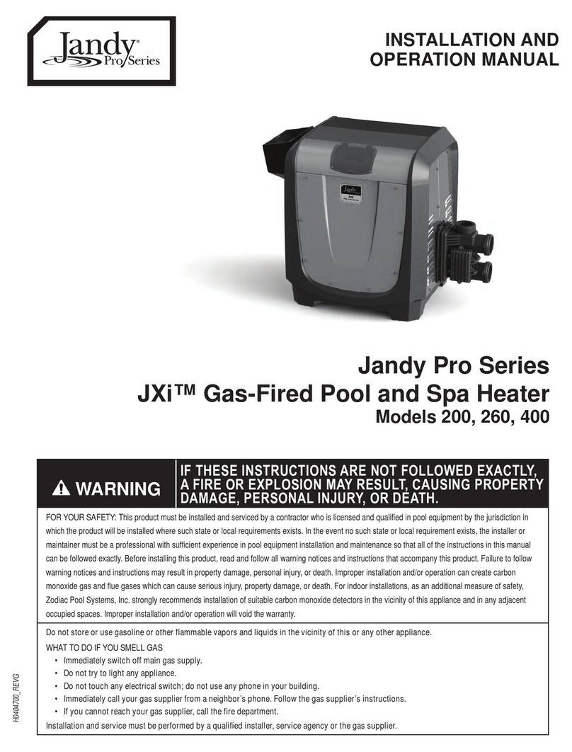
Jandy JXi 200 User manual

Installation and Operation Manual
JXi™
Gas-Fired Pool and Spa Heater
Models: 200
260
400
WARNING
FOR YOUR SAFETY – This product must be installed and serviced by a contractor who is licensed and qualified in pool equipment by the jurisdiction in which the product will be installed
where such state or local requirements exist. The maintainer must be a professional with sufficient experience in pool equipment installation and maintenance so that all of the instructions
in this manual can be followed exactly. Before installing this product, read and follow all warning notices and instructions that accompany this product. Failure to follow warning notices
and instructions may result in property damage, personal injury, or death. Improper installation and/or operation may void the warranty.
Improper installation and/or operation can create unwanted electrical hazard which may cause serious injury, property damage, or death.
ATTENTION INSTALLER – This manual contains important information about the installation, operation and safe use of this product. This information should be given
to the owner/operator of this equipment.

Page 2
Jandy®JXi™Gas-Fired Pool and Spa Heater | Installation & Operation Manual
Table of Contents
EQUIPMENT INFORMATION RECORD
DATE OF INSTALLATION _______________________________________________________________________________
INSTALLER INFORMATION _____________________________________________________________________________
INITIAL PRESSURE GAUGE READING (WITH CLEAR FILTER) ____________________________________________
PUMP MODEL ________________________________ HORSEPOWER ____________________________________
NOTES _______________________________________________________________________________________________
______________________________________________________________________________________________
______________________________________________________________________________________________
Section 1. General Information......................... 4
1.1 Introduction ....................................................4
1.2 Important Safety Instructions......................... 4
1.3 Warranty.........................................................5
1.4 Technical Assistance......................................5
1.5 Specifications................................................. 5
1.6 Dimensions..................................................... 6
1.7 Certification Codes and Standards............... 6
1.8 Heater Components.......................................7
Section 2. Getting Started................................. 8
2.1 Package Contents.......................................... 8
2.2 Required Equipment ......................................9
Section 3. Location Requirements................. 10
3.1 Clearances ...................................................10
3.2 Outdoor Installations.................................... 11
3.3 Indoor and Outdoor Shelter Installation.......13
Section 4. Gas Connections ...........................21
4.1 Supply Gas Requirements ...........................21
4.2 Gas Inlet Pressure........................................ 22
4.3 Special Precautions for LP Gas ...................22
Section 5. Water Connections ........................23
5.1 Pump Sizing .................................................23
5.2 Plumbing Connections.................................24
5.3 Water Pressure Switch Adjustment .............26
5.4 Check Valve Installation ............................... 27
5.5 Pressure Relief Valve Installation ................. 27
5.6 Auxiliary Components, Chlorinators, Ozone
Generators and Sanitizing Chemicals .........30
Section 6. Electrical Connections ..................30
6.1 Service Access.............................................31
6.2 Main Wiring Connections ............................. 31
6.3 Input Voltage and Conversion......................32
6.4 Bonding........................................................33
Section 7. Optional Remote Controls ............ 34
7.1 Connecting to Remote Pool-Off-Spa
Selector (3-Wire Connection) ......................34
7.2 Connecting to an AquaLink Control System
or Remote TSTAT (2-Wire Connection)........ 34
7.3 “Smart” Communication via RS-485 ........... 35

Page 3
Jandy®JXi™Gas-Fired Pool and Spa Heater | Installation & Operation Manual
Section 8. Operating Instructions .................. 37
8.1 Important Safety Instructions....................... 37
8.2 First-Time Start-Up Procedure.....................38
8.3 To Turn Off Gas to the Heater...................... 39
8.4 Normal Operation......................................... 39
8.5 Operating the Controller............................... 40
8.6 Performing Seasonal Shutdown ..................41
Section 9. Maintenance................................... 42
9.1 Water Chemistry...........................................42
9.2 Swimming Pool Energy Saving Tips ............ 43
9.3 Winterizing.................................................... 44
9.4 Spring Startup ..............................................44
9.5 Inspection and Service................................. 44
Section 10. Troubleshooting.............................46
10.1 Common Problems ......................................46
10.2 Service Diagnostic Messages ...................... 47
10.3 Ignition Control LED Service Codes.............48
Section 11. Professional Service and
Maintenance................................... 48
11.1 Header Bypass Reassembly
Recommendations .......................................48
Section 12. Spare Parts.....................................49
12.1 Major Components ......................................49
12.2 Cabinet Assembly Spare Parts List and
Exploded Parts Diagram ..............................50
12.3 Heat System Spare Parts List and
Exploded Parts Diagram ..............................51
12.4 Water System Spare Parts List and
Exploded Parts Diagram ..............................53
12.5 Electrical System Spare Parts List and
Exploded Parts Diagram ..............................54
Section 13. Appendix A. ASME Header............55
13.1 Dimensions (from “Section 1.6 Dimensions”
on Page 4) ....................................................55
13.2 Package Contents (from “Section 2.1 Package
Contents” on Page 6) ................................... 55
13.3 Pump Sizing (from “Section 5.1 Pump Sizing”
on Page 20) ..................................................56
13.4 Cabinet Assembly Spare Parts List and
Exploded Parts Diagram ..............................59
13.5 Water System Spare Parts List and
Exploded Parts Diagram ..............................61

Page 4
Jandy®JXi™Gas-Fired Pool and Spa Heater | Installation & Operation Manual
Section 1. General Information
READ AND FOLLOW ALL INSTRUCTIONS
1.1 Introduction
This manual provides installation and operation instructions for the Jandy JXi pool and spa gas heater
product line. Readthese installation and operation instructions completely before proceeding with the
installation. Consult Zodiac Pool Systems LLC (“Zodiac”) with any questions regarding this equipment. To
obtain additional copies of this manual contact us at 800-822-7933.
Zodiac Pool Systems LLC
2882 Whiptail Loop #100
Carlsbad, CA 92010 USA
The blower draws air and fuel through specially designed orifices, delivering a precise mixture to the burner,
located inside the sealed combustion chamber. Water flows through the heat exchanger, which surrounds the
burner transferring the heat to the water. Exhaust gases are then directed through a duct where it is vented to
the atmosphere.
1.2 Important Safety Instructions
The heater is designed and manufactured to provide many years of safe and reliable service when installed,
operated, and maintained according to the information in this manual and the installation codes referred to
throughout. Be sure to read and comply with all warnings and cautions.
WARNING
Improper installation or maintenance can cause nausea or asphyxiation from carbon monoxide in flue gases which could result in severe injury, or
death. For indoor installations, as an additional measure of safety, Zodiac Pool Systems LLC strongly recommends the installation of suitable Carbon
Monoxide detectors in the vicinity of this appliance and in any adjacent occupied spaces.
WARNING
The following “Safety Rules for Hot Tubs”, recommended by the U.S. Consumer Product Safety Commission, should be observed
when using the spa:
• Spa or hot tub water temperature should never exceed 104°F (40°C). One hundred degrees Fahrenheit (100°F [38°C]) is considered safe for a healthy adult. Special caution is
recommended for young children.
• The drinking of alcoholic beverages before or during spa or hot tub use can cause drowsiness which could lead to unconsciousness, and subsequently result in drowning.
• Pregnant women take note! Soaking in water above 102°F (38.5°C) can cause fetal damage during the first three (3) months of pregnancy (which could result in the birth
of a brain-damaged or deformed child). If pregnant women are going to use a spa or hot tub, they should make sure the water temperature is below 100°F (38°C) maximum.
• The water temperature should always be checked with an accurate thermometer before entering a spa or hot tub. Temperature controls may vary by as much as 1°F (1°C).
• Persons with a medical history of heart disease, diabetes, circulatory or blood pressure problems should consult their physician before using a hot tub or spa.
• Persons taking any medication which induces drowsiness (e.g., tranquilizers, antihistamines, or anticoagulants) should not use spas or hot tubs.
WARNING
Prolonged immersion in hot water can induce hyperthermia.
Hyperthermia occurs when the internal body temperature reaches a level several degrees above the normal body temperature of 98.6°F (37°C).
Symptoms include dizziness, fainting, drowsiness, lethargy, and an increase in the internal body temperature. The effects of hyperthermia include:
• Lack of awareness of impending hazard
• Failure to perceive heat
• Failure to recognize need to leave spa
• Physical inability to leave spa
• Fetal damage in pregnant women
• Unconsciousness resulting in a danger of drowning
SAVE THESE INSTRUCTIONS

Page 5
Jandy®JXi™Gas-Fired Pool and Spa Heater | Installation & Operation Manual
1.3 Warranty
The Jandy JXi heater is sold with a limited factory
warranty.
Make all warranty claims to your Jandy dealer or
directly to Jandy. Claims must include the heater
serial number and model (this information can be
found on the rating plate), installation date, and
name of the installer. Shipping costs are not included
in the warranty coverage.
The warranty does not cover damage caused
by improper assembly, installation, operation,
winterizing, field modification, or failure to earth bond
and properly ground the unit. Also, damage to the
heat exchanger by corrosive water is NOT covered
by the warranty.
1.4 Technical Assistance
Consult the Jandy technical support department or
your local Jandy dealer with any questions or problems
involving your Jandy equipment. An experienced
technical support staff is ready to assist you in
assuring the proper performance and application of
Jandy products. For technical support call the Jandy
technical support department at (800) 822-7933.
1.5 Specifications
Supply Gas
INSTALLATION LOCATION* NATURAL GAS (NG) CERTIFIED INDOOR (US ONLY), OUTDOOR / COVERED SHELTER
LIQUID PROPANE (LP) OUTDOOR / COVERED SHELTER
OUTDOOR OPERATION AMBIENT
AIR ANY OUTDOOR OPERATION IN AMBIENT AIR UP TO 40°F (4°C)
GAS PIPE HEATER GAS VALVE
CONNECTION†
NATURAL GAS (NG) 3/4 in NPT
LIQUID PROPANE (LP)
Inlet Gas supply Pressure ‡
Min
NATURAL GAS (NG) 4.0 in WC
LIQUID PROPANE (LP)
Water Pipe/Heater Connection NATURAL GAS (NG) • PVC/CPVC 2 in unthreaded
• Jandy threaded union
LIQUID PROPANE (LP)
Water Flow Rate
Min
NATURAL GAS (NG) 30 gpm
(76 lpm)
LIQUID PROPANE (LP)
Working Water Pressure NATURAL GAS (NG) 2 psi**
LIQUID PROPANE (LP)
Exhaust Vent Connection Size (Cate-
gory I)§ See Section 3.3.4
NATURAL GAS (NG) • Model 200: 6 in
• Model 260: 7 in
• Model 400: 8 in
LIQUID PROPANE (LP)
Exhaust Vent Connection Size (Cate-
gory III)§ See Section 3.3.4
NATURAL GAS (NG) • All Models: 4 in
LIQUID PROPANE (LP)
Electrical Supply NATURAL GAS (NG) • 120 VAC@<5amps
• 240 VAC@<2.5amps
LIQUID PROPANE (LP)
High Altitude
NATURAL GAS (NG)
Appliances are normally derated when installed at high elevation. This is
not necessary with the JXi heater because it has a special venturi-type
combustion system which self-compensates for changes in barometric
pressure. Air flow through the blower inlet pulls the correct flow of gas into
the burner regardless of air density.
JXi heaters are CSA certified for elevations of up to 4,500 feet above sea
level. At elevations above 4,500 ft., the heater BTU output can be expected
to be reduced by 4% for every 1,000 feet over 4,500 feet above sea level.
LIQUID PROPANE (LP)
* Indoor installation is not recommended for liquid propane heaters.
**Adjustable water pressure switch factory set to 7 psi.
See section 5.3 for adjustment instructions.
Review Special Precautions for liquid propane heaters (Section 4.3)
Any changes to the heater, gas controls, gas valve, air orifice, gas orifices, wiring, or
improper installation may void the warranty. If change is required to any of the above;
contact your local Jandy distributor, visit www.jandy.com or call technical support at
800.822.7933.
†For gas pipe size requirements see Section 4
‡Value displayed is for operating (fired) pressure not static.
§ Use type B double-wall gas vent, per table 13.1(a) NFPA 54

Page 6
Jandy®JXi™Gas-Fired Pool and Spa Heater | Installation & Operation Manual
1.6 Dimensions
Figure 1. General Dimensions
For ASME heater models JXi400NC, JXi400PC, JXi260NC and JXi260PC please go to “Appendix A. ASME®Header” on page 55.
22.1 in (56 cm)
24.9 in
(63 cm)
16 in
(40.6 cm)
21.6 in (55 cm)
5.1 in
(13 cm)
5.6 in
(14 cm)
10.13”
(26 cm)
18.5”
(47 cm)
5.6 in
(14 cm)
10.13 in
(26 cm)
Versa Plumb®
Inlet
18.5 in
(47 cm)
35.4 in (90 cm)
26.5 in
(67 cm)
22.1 in (56 cm)
24.9 in
(63 cm)
16 in
(40.6 cm)
21.6 in (55 cm)
35.4 in (90 cm)
26.5 in
(67 cm) Inlet
Dimensions are identical
for all heater models
1.7 Certification Codes and Standards
USA CANADA
Design Certified CSA (Canadian Standards Association)
Compliant
ANSI® Z21.56
California South Coast Air Quality Management
District’s (SCAQMD) Rule 1146.2
CSA 4.7
National Codes
National Fuel Gas Code Natural Gas and
Propane Installation Code
NFPA® 54/ANSI Z223.1 CAN/CSA-B149.1
Pay particular attention to the chapter addressing
Venting of Equipment
Minimum combustion air requirements MUST be followed for
proper and safe operation. Failures may occur when only the
minimum combustion air openings are used.
All Jandy heaters must be installed in accordance with the local building and installation codes as per the utility or Authority Having Jurisdiction
(AHJ). In the absence of local codes, please refer to the latest edition of the national codes for installation.
JXi pool and spa heaters meet or exceed the requirements of energy conservation regulations such as those in states that have disallowed the use of
continuously lit pilot type ignition sources.

Page 7
Jandy®JXi™Gas-Fired Pool and Spa Heater | Installation & Operation Manual
1.8 Heater Components
Front
Rear
Header
a
Monitors temperature at the exhaust flue. If
excessive temperatures are detected,
combustion will stop and a fault will be displayed.
Flue Temperature Sensor
a
Indicates a safety control equipped to protect internal
components and extend the life of the heater.
bcdd efghi
Controls gas flow into the burner. Enables flow when the
temperature control calls for heat and all safety controls
enable operation. It also regulates gas pressure to -0.2” WC (Water Column)
below the air pressure at the blower inlet. Necessary pressure regulation
cannot be accomplished with common (positive pressure) gas valves.
Gas Valve
g
When current is passed through the ceramic
material of the igniter it will achieve temperatures
great enough to initiate combustion of the air/fuel mixture.
Hot Surface Igniter
b
Provides energy for ignition, monitors flame quality
and controls the gas valve. Upon call for heat, the
blower is activated to purge the combustion chamber. Electrical power is
then applied to the hot surface igniter. When ignition temperature is
attained, the gas valve opens and ignition occurs. If stable flame is detected
the igniter will power down. If stable flame is not detected the control
system will close the valve to prevent further gas release. If a total of 3
ignition attempts fail an ignition fault is displayed.
Ignition Control
c
Prevent water of excessive temperatures from
being discharged from the heater. If either switch,
one at the heat exchanger first pass 135°F (57°C) and one at the heat
exchanger outlet 150°F (65°C), senses excessive temperature, the gas
valve will close and combustion will stop.
High Limit Switches
d
Senses water temperature by
means of a thermistor. Heater
will operate to attain and maintain the water temperature according to the
heater settings. Two separate thermostat settings are supported, typically
used to set pool and spa temperatures.
Pool/Spa Water Temperature Control
e
Senses whether or not water is available to
the heater by measuring back pressure at the
header inlet. If insufficient pressure is detected, the display will indicate a
“Check Flow” fault and combustion will stop.
Water Pressure Switch
f
Draws in air and fuel gas
creating an air/fuel mixture that
is passed through the burner for combustion. The fan will operate for
several seconds before flame initiation and after the flame is extinguished
to purge the combustion chamber for a clean burn and to expel any
residual exhaust gas.
Combustion Blower and Air Orice
h
Monitors the vacuum (negative pressure) within
the blower housing. This switch verifies that air is
flowing through the combustion system by sensing pressure. If air flow is
inadequate, combustion will stop and a fault will be displayed.
Air Pressure Switch
i

Page 8
Jandy®JXi™Gas-Fired Pool and Spa Heater | Installation & Operation Manual
1
2
3
4
56
NOTE:
1 EA of item 4, item 5 and
item 6 will come pre-installed at
the horizontal manifold inlet.
Section 2. Getting Started
Install the JXi in accordance with the procedures
in this manual, local codes and ordinances, and in
accordance with the latest edition of the appropriate
national code. See Section 1.7.
If the heater is to operated in below freezing
conditions it should be installed in a protected
outdoor shelter. See Section 3.3.
All gas-fired products require correct installation to
ensure safe operation.
The requirements for pool heaters include the
following:
• Field assembly (if required)
• Appropriate site location, clearances and flooring
• Sufficient combustion and ventilation air
• Properly sized gas meter and piping
• Proper electrical wiring
• Sufficient water flow
This manual provides the information needed to
meet these requirements. Review all applications
and installation procedures before continuing the
installation.
JXI400P
DIRECT IGNITION
E15XJ1232
399,000
JXI, US
Zodiac Pool Systems LLC
2882 Whiptail Loop #100, Carlsbad CA 92010
CSA Certified for installations up to 4,500 FT (1,372m), BTU output
is reduced about 4% per 1000 ft (305 m) over 4,500 ft (1,372m). In
general efficiency is not affected by altitude.
ALTITUDE:
2.1 Package Contents
For ASME heater models JXi400NC, JXi400PC, JXi260NC and JXi260PC please go to “Appendix A. ASME®Header” on page 55.
Before completely unpacking the unit please inspect carton for damage. In addition, please check the carton
label to ensure that you have the correct fuel type and BTU rating for your application.
JXI400N
DIRECT IGNITION
E15XJ1000
399,000
JXI, US
Zodiac Pool Systems LLC
2882 Whiptail Loop #100, Carlsbad CA 92010
CSA Certified for installations up to 4,500 FT (1,372m), BTU output
is reduced about 4% per 1000 ft (305 m) over 4,500 ft (1,372m). In
general efficiency is not affected by altitude.
ALTITUDE:
Item Description Qty.
1 JXi Heater 1
2 Versa Plumb®Sweep Elbow 1
3 2 in Universal Union Tailpiece 2
Item Description Qty.
4 2 in Universal Union Cap 1
5 2 in Universal Union O-ring 3
6 2 in Universal Union Nut 3
OR

Page 9
Jandy®JXi™Gas-Fired Pool and Spa Heater | Installation & Operation Manual
2.2 Required Equipment
Please ensure that the following equipment is available to the installer at the time of installation.
2.2.1 Tools
Safety Eyewear Gloves Phillips Screwdriver Flathead
Screwdriver Pipe Wrench
Adjustable Wrench 3/16 in Hex Key Channel Locks Digital Differential
Manometer Voltage Meter
PVC Pipe Cutter Power Drill Tape Measure
Gas Supplies Electrical
Supplies
Plumbing
Supplies
Appropriately sized Gas
Piping (see Section 4.1) 120 or 240 VAC PVC Piping
Manual Gas Shut Off Valve Conduit Elbow/
Conduit connector. PVC Cement
Gas Union Flexible Conduit PTFE (Teflon™)
Tape
Gas Pipe Cap Wire Nuts (3 ea.)
Leak Solution
1/16 in Hose “T”
1/8 in - 1/16 in Barbed
Adapter
1/16 in Flexible Hose
2.2.2 Materials Supplied by Installer
Please ensure that all materials used during the
installation are in accordance with local codes or the
authority having jurisdiction (AHJ) requirements. If
you have any questions regarding the materials that
need to be used during this installation please call
the Zodiac customer service center at 1-800-822-
7933.
Indoor installations will require additional venting and
exhaust conversion materials which are outlined in
detail in Section 3.3.
NOTE: Required materials may differ from the materials
listed. Be sure to confirm with all local and
national codes before beginning the installation.

Page 10
Jandy®JXi™Gas-Fired Pool and Spa Heater | Installation & Operation Manual
Section 3. Location Requirements
The JXi heater is shipped from the factory with an
exhaust vent configured for outdoor installation. The
heater is also design-certified for indoor installations
in the United States and for outdoor shelter
installations in Canada. See Section 3.3 for details.
Location of the heater below or above the pool water
level affects operation of its water pressure switch.
See sections 5.3 for more information.
Equipment must be installed on a firm, solid, non-
absorbent level surface; and per the requirements of
local codes and Authority Having Jurisdiction (AHJ).
Equipment can weigh up to 156 lbs. (57 kg). Use
suitably rated mounting surface materials to avoid
risk of settlement, and never use sand to level the
equipment as the sand will wash away. Check local
building codes for additional requirements.
NOTE: If the heater is to be operated in below freezing
conditions it should be installed in a protected
outdoor shelter.
CAUTION
When pool equipment is located below the pool surface, a leak
from any component can cause large scale water loss or flooding.
Zodiac Pool Systems LLC cannot be responsible for such water loss or
flooding or resulting damage.
required per CSA B149.1, section 4.14.2.
Combustible
Surface
6 in (15 cm)
Service
Clearance
TOP: 36 in (92 cm)
FRONT: 18 in (46 cm) USA
24 in (61 cm) Canada
NOTE:
Clearances are manufacturer’s
tested values. These are given as minimum
values. Where local and national codes
apply, and if the clearance values specified
in the applicable codes are different than
those listed in this manual, use the greater
value to ensure safest operation.
NOTE: Service clearance may be
needed from the rear if the top panel
is reversed.
Figure 2. Clearances
3.1 Clearances
The heater must be installed in a location that
allows clearances for maintenance and inspection.
Minimum distances from combustible surfaces must
also be maintained. All criteria given in the following
sections reflect minimum clearances as stated in the
national standards. However, each installation must
also be evaluated, taking into account prevailing
local conditions such as wind speed and direction,
proximity and height of obstructions that may block
ventilation, and proximity to public access areas.
Service Clearance: 36 inches (92 cm) from top of
heater for removal of top panel.
18 inches in the US and 24 inches (61 cm) in Canada
from the front panel of the heater. One exception
to this is if the top panel is reversed such that the
water plumbing is now on the left hand side of the
heater and the exhaust is on the right hand side. In
this case, you will need the service clearance (18”
US/24” Can) from the rear panel of the heater.
Combustible Surfaces: Each heater face requires a
6 inch (15 cm) clearance from combustible surfaces.
Although it is not advisable, the heater base can
be placed on a combustible surface for operation.
However, do not install the heater on carpet.

Page 11
Jandy®JXi™Gas-Fired Pool and Spa Heater | Installation & Operation Manual
3.2 Outdoor Installations
Locate the heater:
• On a level solid surface
• 5 ft (1.5 m) from inner pool edge unless separated
by a permanent solid barrier, i.e. a wall or fence
• In an open area, not under a deck or other
structure
• Away from doors windows or louvers that connect
in any way to occupied or inhabited areas of the
building
NOTE: In Canada the top of the exhaust vent must be at
least 10 feet (3 m) from any building opening.
• Away from rainwater runoff
• Away from potential sprinkler water intrusion
• So that the top of the heater is at least 3 feet (1 m)
below any overhang
• So that the top surface of the heater is at least 3
feet (1 m) above any forced air inlet within 10 feet
(3 m)
• This heater is approved for use outdoors without
additional venting attachments. If there are
concerns over extreme weather conditions, we
do provide the option to add up to 25 feet (7.5 m)
of Category III venting material with an approved
vent termination cap. Refer to section 4.3.4 for
details.
min. 5 ft (1.5 m)min. 5 ft (1.5 m)
unless the heater is
separated from the pool by
a solid fence, wall or other
permanent solid barrier.
Locate the heater on a level surface in an open, unroofed area.
Do not install the heater under a deck.
The heater must be installed on a level, solid, and firm surface or platform.
Although it is always advisable to install the heater on a non-combustible
surface, the JXi-series has been CSA-certified for installation on solid,
firm, and level combustible surfaces. DO NOT INSTALL ON CARPET.
Do not
locate the heater
below or adjacent to any
doors, windows, louvers,
grills, etc., which connect
in any way with an
inhabited area of a
building, even though the
access might be through
another structure (e.g., a
garage or utility room).
If the heater is installed close to a structure, protect it from rain water runoff
with rain gutters on the roof or other measures.
Be sure to divert rain water runoff away from heater
The area under an
overhang must be
open on three sides to
prevent combustion
gases from being
diverted into living
areas through doors,
windows, or gravity
inlets
In the United States install the heater so that there is at least a
three (3) foot (1 m) clearance between the bottom of the
overhang to the top of the heater exhaust vent.
Do not install the heater with the top of the vent assembly within
4 feet (1.22 m) horizontally, 4 feet (1.22 m) below or less than 1 ft
(300 mm) above of any opening into a building. Local codes and
installation requirements may vary.
In Canada, install the heater so that the top of the vent is at least
10 feet (3.0 m) from any building opening.
The top of the heater exhaust vent must be at least 3 feet (1 m) above any
forced air inlet, or intake ducts located within 10 feet (3.0 m) horizontally
Do not
locate the heater near sprinkler
systems that could spray water on it.
Water from sprinklers can damage
controls and electronic components.
Figure 3. Location Requirements
WARNING
United States
Do not install the heater with the top of the vent assembly within 4
feet (1.22 m) horizontally, 4 feet (1.22 m) below or less than 1 ft (300
mm) above of any opening into a building. Local codes and installation
requirements may vary.
Canada
Do not install the heater with the top of the vent assembly within 10
feet (3.0 m) of any opening into a building. Local codes and installation
requirements may vary.

Page 12
Jandy®JXi™Gas-Fired Pool and Spa Heater | Installation & Operation Manual
3.2.1 Anchor Bracket Installation
Anchor brackets do not come standard with the
JXi. If you require the anchor brackets for your
installation please order kit #R0593400.
Anchor brackets should be installed in any
circumstance where the heater may be subject
to natural risks such as extreme weather or
earthquake. In Florida, the heater is required to
be securely fastened to the equipment pad to
meet the applicable requirements of the Florida
Building Code. Other jurisdictions may have similar
requirements for extreme weather or other natural
hazards. Check your local codes for details.
a
Using an adjustable wrench or equivalent tool
loosen (DO NOT REMOVE) the retaining nut on the
bracket. The upper and lower anchor bracket should
be able to rotate freely about the retaining pin.
b
Slide the bracket into the slot located at the lower
corner of the heater base.
c
Rotate lower anchor bracket into final position.
Ensure that the lower anchor bracket is flush with the
equipment pad surface and level.
d
Tighten the retaining nut so that the anchor
bracket assembly is secure.
e
Drill a hole in the concrete using the lower anchor
bracket hole as a guide. It is advised that a hammer
drill with an appropriate concrete drill bit be used.
f
Place a screw in the hole and tighten to fasten
the anchor bracket to the concrete pad. Do not over
torque the screws.
NOTE: Depending on the location of and access to the
bracket, it may be necessary to mark the drill
location using the lower anchor bracket hole as
a guide. Remove the bracket from the heater,
drill the hole and then reattach the bracket to the
heater base.
NOTE: Concrete screws are not provided in the anchor
bracket kit. Use size 1/4 in x 2-1/4 in galvanized
or plated concrete screws and washers.
a
c
d
b
e
f
Anchor Bracket Upper
Anchor Bracket Lower
Concrete Equipment Pad
ANCHOR BRACKET INSTALLATION
SECTION VIEW
Concrete Screw
JXi™ Heater Base
Anchor Bracket Slot
Retaining Nut
Retaining Pin

Page 13
Jandy®JXi™Gas-Fired Pool and Spa Heater | Installation & Operation Manual
3.3 Indoor and Outdoor Shelter Installation
Due to the higher risks and hazards of liquid propane
(LP) gas, Zodiac®does not encourage installation of
LP gas heaters indoors, refer to Section 4.3.
The heater is CSA design-certified for indoor
installations in the US and for outdoor shelter
installations in Canada. Please keep in mind
the service and combustible surface clearances
from Section 3.1 when selecting an installation
3.3.1 Combustion Intake Air Supply
Minimum pitch
per 12 in. of pipe:
1/4 in (6.35 mm)
JXi 200
50 in2
323 cm2
65 in2
419 cm2
100 in2
645 cm2
JXi 260
JXi 400
Minimum Net Free Open Area*
Combustion Openings
Horizontal Duct
4
2
1.5Screens or Metal Louvers
Wood Louvers
Multiply required
opening above by*if air passes through:
In Canada the
installation must
be in accordance
with the latest edition
of CAN/CSA B149.1.
All outdoor
shelter and
indoor
installations
must have
uninterrupted
openings to
outside air for
combustion and
ventilation. Do
not, under any
circumstances,
install this
product in an
indoor location
which does not
provide
combustion air
to the appliance
from outside
the building.
For garage installation, heater base must be 18 in (46 cm) above the floor.
Within 12 in. (30.5 cm)
Listed Vent Cap
Use Approved Rook Jack
Storm Collar
Within 12 in. (30.5 cm)
2 ft. (61 cm) Min.
Height required
for any roof surface
within 10 ft. ( 3m)
3 ft. (91.5 cm) Minimum
Above Highest Outlet Point
10 ft. (3 m)
Greater Than 10 ft. (3 m)
Figure 4. Indoor and Outdoor Shelter Installation
location. You will also need to make considerations
for intake combustion air see Section 3.3.1 and
exhaust venting see Section 3.3.5. In addition, when
pool equipment is installed indoors, appropriate
containment measures and drains should be
considered for the prevention of property damage in
the event of a water leak.
NOTE: An outdoor shelter is an unoccupied enclosure
which does not communicate directly with
occupied areas.
If the outdoor shelter is a completely closed
structure, air openings in accordance with the
size recommendations described in Section 3.3.1
must be maintained. If the structure does not have
outside air openings then air must be provided for
combustion by using our fresh air vent kit.
As outlined in the latest edition of ANSI®
standard Z223.1 (NFPA®54), the heater
location must be properly vented to provide
sufficient air supply for proper combustion.
When combustion air is supplied directly
through an outside wall, each opening should
have a minimum free area of 1 square inch
per 4,000 BTU/h (1.2 kW) input of the total
input rating of all appliances in the enclosed
area. If combustion air must pass through
horizontal ducts, each opening should have a
minimum free area of 1 square inch per 2,000
BTU/h (1.2 kW) input of the total input rating
of all appliances in the enclosed area. Details
can be found in Figure 4.
The “Minimum Net Free Open Area”
information from Figure 4 is not applicable in
installations where exhaust fans or blowers
of any type are used. Any equipment which
exhausts air from the room where the heater
is installed can deplete the combustion air
supply which could lead to poor combustion,
decreased heater efficiency and reliability
and increased emissions. This could
cause flue products to accumulate in the
room. Additional air must be supplied to
compensate for such exhaust. Consult
a professional engineer to ensure that
installations where exhaust fans or blowers
are used are designed and installed in
accordance with all applicable local and
national installation codes.
In addition, the heater must be completely
isolated and protected from any source of
corrosive chemical fumes or corrosive vapors
(i.e chlorine or hydrochloric acid).

Page 14
Jandy®JXi™Gas-Fired Pool and Spa Heater | Installation & Operation Manual
WARNING
Do not store any chemicals, cleaners, or other corrosive material near combustion air openings or in the room. Avoid locating appliance vents in
the vicinity of combustion air openings. Failure to prevent corrosive materials from mixing with combustion air can result in reduced heater life and
unsafe heater operation.
3.3.2 Direct Venting
If you plan to supply the intake air directly to the heater, refer to Sections 3.3.3 and 3.3.4.
c
Align the orifice adapter with the orifice tabs and
secure with four screws.
Air Orifice
Air Orifice
Adapter
75 mm
(3") PVC
Not Included e
f
c
d
Marker
For indoor installations the exhaust must
also be converted. Order part number
R0731100 and follow the instructions in
The JXi Installation and Operation
Manual H0574300, section 3.3 “Indoor
and Outdoor Shelter Exhaust
Conversion”.
d
Dry fit the 3 in (75 mm) PVC tubing into the orifice
adapter. Mark screw hole locations with a pen.
Remove and drill pilot holes in the PVC. Fit the PVC
into the orifice adapter, align the holes and secure
with four screws. In the case of the JXI400 (399,000
BTU models), up to a 6 in (152 mm) length of 3 in
(75 mm) PVC can be used before increasing it to 6 in
(152 mm) diameter PVC pipe.
e
Reinstall the air orifice and air hoses.
f
Install the new rear panel over the PVC and
secure with four screws.
3.3.4 Exterior Venting and Air Intake
The JXi must be vented to the outdoors. It must not
be vented in common with any other appliance, even
if that appliance is of the condensing type. Common
venting can result in severe corrosion of the JXi or
of the other appliances or their venting, or escape of
combustion product gases through such appliances
or vents. Do not vent the JXi to a fireplace chimney
or building chase.
Combustion air ducting, when provided, must not be
shared with any other appliance or with another JXi.
Doing so may result in flow of air through the other
appliances instead of directly from the outdoors.
The combustion air intake and vent outlet must
be located exterior to the building and in the
same pressure zone - i.e. both through the roof or
both through a side wall. The vent terminal must
be located in accordance with local codes, as
applicable, and in accordance with the following:
3.3.3 Direct Air Intake
In certain applications it may be necessary to supply
intake air directly to the heater. You will need to
order and install the direct air conversion R-Kit
R0724600.
A total equivalent length of 65 ft (20 m) of 3 in (75
mm) PVC tubing can be used on the JXI200 and JXI
260 models. A total equivalent length of 65 ft (20
m) of 6 in (152 mm) PVC tubing can be used on the
JXI400 models. Please be aware that each elbow
used will account for 12 ft (3.6 m) of length.
Gas Valve
Hose Port
Air Pressure
Switch
Hose Port
Air Orifice
Air Orifice
Screen ba
For ease of access, remove the rear and top panels.
a
Loosen the two screws securing the air orifice
and screen in place. Remove the air pressure switch
and gas valve hose from the air orifice.
b
Remove the air orifice, separate and dispose of
the orifice screen.
TIP: When removing the air hoses
form the air orifice, mark the hoses
with tape or a marker to help with
reassembly.

Page 15
Jandy®JXi™Gas-Fired Pool and Spa Heater | Installation & Operation Manual
• Locate the vent terminal so that it will not be
damaged by pedestrians and other traffic, and so
that the discharge is not offensive. The National
Fuel Gas Code requires a through-wall vent
terminal be at least 7 feet (2.13 m) above grade if
located at a public walkway.
• Locate the vent terminal so the vent exhaust does
not settle on building surfaces and other nearby
objects. Vent products may corrode such surfaces
or objects.
• Locate the vent terminal at a sufficient horizontal
distance from any gas or electric metering,
regulating or relief equipment. In the United
States, this distance must be at least 4 feet (1.22
m). In Canada, it must be at least 10 feet (3.05 m).
• Locate the vent terminal at a sufficient horizontal
distance from any building opening. Take special
care to assure that combustion products do
not enter a building through windows, doors,
ventilation inlets, etc. In the United States, this
distance must be at least 4 feet (1.21 m). In
Canada, it must be at least 10 feet (3.04 m).
As shown in Figure 5 and Figure 6, the combustion
air intake and the vent outlet must be installed no
closer together than 18 in (45.7cm) and no farther
apart than 60 in (1.5m). The combustion air inlet
opening must face downward to prevent entry of rain
or snow. The vent outlet must discharge away from
the combustion air inlet - normally in a horizontal
direction when on a wall and vertically upward
when on a roof. Both should terminate at least 12
in (30.5cm) above the snow accumulation level. In
locations with freezing climate, extension of the vent
pipe outside of the building should be minimized.
Vent Exhaust
Pipe
Combustion
Air Pipe
7” min
6” min
18” min
60” max
Grade level
or normal snow
12” min. to maximum
snow level
HOT
Vent
Termination
Cap
Figure 5. Vent and combustion air terminals at
exterior wall
Connect the vent pipe to the heater vent collar
with an air-tight corrosion-resistant clamp. The
connection must not allow leakage of combustion
products into the space but should be removable for
service.
Install vent piping with a continuous rise of at least
1/4 in per foot (20 mm per meter) away from the
heater. This will assure that any condensate forming
in the vent pipe will flow back to the heater where it
can be disposed of properly.
Support vent piping with suitable hangers so its
weight does not bear on the heater or building
penetration and so that piping joints are not strained.
Support horizontal runs at intervals no greater than
6 feet (1.82 meters), and closer if necessary to avoid
sagging. Sagging can trap condensate water and
block the vent.
NOTE: Both combustion air and vent piping joints
must be sealed appropriately. Connection of
combustion air and vent piping to the heater
should be serviceable - i.e. removable for heater
service.
Vent Termination Cap
Vent Exhaust
Pipe
Combustion
Air Pipe
Elbow
A
A
18” min
60” max
Plumbing Vent
Roof Boot
A = Maximum snow accumulation level + 12”
Figure 6. Vent and combustion air terminals at roof

Page 16
Jandy®JXi™Gas-Fired Pool and Spa Heater | Installation & Operation Manual
3.3.5 Exhaust Venting
When the JXi heater is installed indoors or in an
outdoor shelter it can be vented as a Category I or
Category III appliance. In either case, the vent pipe
sizing must be in accordance with the specifications
listed in Table 1.
For cases when the heater is installed outdoors and
there is concern over extreme weather conditions,
we also provide the option of adding Category III
venting per the specifications listed in Table 1.
It is recommended that all venting be engineered by
a licensed mechanical contractor.
• Category I: Appliance operates with a negative
vent static pressure, a vent gas temperature that
avoids excessive condensate production and
will vent vertically terminating at the roof. Venting
materials for Category I must be Type B double
wall vent.
• Category III: Appliance operates with a positive
vent static pressure, a vent gas temperature that
avoids excessive condensate production and can
be vented horizontally terminating at a side wall.
• Do not terminate heater vents near air conditioning
or air supply fans which could pick up exhaust
flue products, such as carbon monoxide and other
hazardous effluent, and return them inside the
building.
• Vent pipe type and material must be carefully
selected and depends on the type of installation.
• Do not locate the vent terminal where exhaust
flue products could strike against building
materials and cause degradation.
• Vent opening should be well away from
landscaping or other obstructions that would
prevent free air flow to and from vent terminal.
• Do not terminate vent under decks, stairs, or car
ports.
• Do not use the appliance to support the vent
pipe.
• Vent piping must be supported with no low spots
or sagging which could allow condensate to
collect.
• Horizontal runs must be sloped upwards away
from the heater to a vent terminal at a minimum of
1/4 in per horizontal foot (2 cm/m). See Figure 4.
• Install the vent pipe so it can expand and contract
freely with temperature changes.
• Do not run the heater vent into a common vent
with any other appliance.
• It is recommended that vent runs over 18 feet
be insulated to reduce condensation and use
a condensate trap in the vent run close to the
heater, especially in cold climate installations.
• When using Category III vent material, it is
acceptable to use a larger diameter pipe size if
needed. ‡
• For heaters installed outdoors where there
is concern over extreme weather conditions,
Category III venting with approved vent
termination cap can be installed as noted in Table
1 and Section 3.3.7 below.‡
WARNING
Vent pipe materials, sizing, and installation must be as required by the National Fuel Gas Code NFPA 54/ANSI®
Z223.1 or the Canadian Installation
Codes for Gas Appliances CAN/CSA-B149.1. Undersized pipe can result in inadequate venting and oversize pipe can result in vent condensation.
Improper selection of vent pipe material, incorrect sizing of the pipe, and incorrect installation of vent piping can result in release of combustion
products to the indoors. This can cause serious injury or death by Carbon Monoxide poisoning or asphyxiation.
WARNING
Improper installation or maintenance can cause nausea or asphyxiation from carbon monoxide in flue gases which could result in severe injury
or death. For indoor installations, as an added measure of safety, Zodiac Pool Systems LLC strongly recommends installation of suitable carbon
monoxide detectors in the vicinity of this appliance and in any adjacent occupied spaces.
Incorrect design and installation of heater vents and ducts can result in personal injury, damage to property, or death. To avoid such hazards, the
heater must be installed only by a qualified professional service technician.

Page 17
Jandy®JXi™Gas-Fired Pool and Spa Heater | Installation & Operation Manual
It is recommended that all venting be engineered by a licensed mechanical contractor
Codes*
US National Fuel Gas code ANSI® Z223.1 (NFPA®54)
CA CAN/CSA-B149.1
Category
Static Press.
Stack Temp.
Condensate
Termination
Location
Pipe Sizing
Model Pipe Size Special Gas Vent Length†
(Vertical or horizontal)
I Negative High Minimal Roof
200 6 in (15 cm) N/A
260 7 in (18 cm) N/A
400 8 in (20 cm) N/A
III Positive High Minimal Roof or
Side Wall
200
4 in (10 cm)
or larger
65 ft (20 m)
260
4 in (10 cm)
or larger
65 ft (20 m)
400
4 in (10 cm)
or larger
65 ft (20 m)
III Positive High Minimal Outdoor‡
200
4 in (10 cm)
or larger
25 ft (7.5 m)
260
4 in (10 cm)
or larger
25 ft (7.5 m)
400
4 in (10 cm)
or larger
25 ft (7.5 m)
*Ensure that you are referencing the latest edition and pay special attention to the chapter addressing “Venting of
Equipment”.
†For each elbow installed, reduce the run length by 12 feet (3.7m)
‡ Applies to outdoor installed heater with concerns over extreme weather conditions.
Table 1. Vent Pipe Sizing Requirements

Page 18
Jandy®JXi™Gas-Fired Pool and Spa Heater | Installation & Operation Manual
3.3.6 Indoor and Outdoor Shelter Exhaust
Conversion
For both Category I and Category III vent types the
heater must first be converted to an indoor exhaust
type. In order to complete the conversion you will
need to order exhaust conversion R-Kit R0731100.
a
Remove two screws securing the exhaust grill to
the exhaust grill backplate.
b
Remove exhaust
grill.
c
Remove the two
screws securing the
rain shield to the
exhaust backplate.
d
Remove the rain
shield.
e
Remove the
remaining two screws
securing the exhaust
backplate to the
exhaust outlet.
f
Remove the exhaust grill backplate.
g
Using two #10 thread cutting screws secure the
vent adapter from R-Kit R0731100 to the exhaust
outlet.
h
If venting for Category I, install an appropriate
vent pipe increaser to accommodate the correct pipe
size from Table 1. Secure to the vent adapter using
the screw clamp.
When the installation requires horizontal venting in
excess of what is allowed for Category I installations
or calls for horizontal discharge, the JXi may be
installed with a Category III venting system.
Vent the heater either vertically or horizontally
using Al29-4C stainless steel components. Consult
manufacturers such as Z-Flex®or Heat Fab®to
obtain approved components. Venting materials
must comply with UL®1738 for Category III,
Special Gas Vent. Based on the normally
expected flue temperatures of this
appliance. PLASTIC VENTING MUST
NOT BE USED.
i
If venting for Category III, install
appropriate vent pipe from Table 1. Secure
to the vent adapter using the screw clamp to
ensure a proper seal.
Double check that there are no possible leak
paths between joints. If a leak path is identified or
suspected it can be sealed using red RTV 600° F
rated silicone adhesive.
When using parts or materials from other
manufacturers please be sure to follow the
manufacturers instructions completely to ensure
harmonious function.
i
g
h
Vent Elbow
for Category I
OR
for Category III
Increaser
4" Vent Pipe
Vent Adapter
Exhaust Outlet
e
b
f
c
d
Exhaust Grill
Exhaust Grill
Backplate
Rain Shield
Exhaust Outlet
a
a
IMPORTANT NOTE: In the Commonwealth of
Massachusetts, additional requirements, covered
in document CMR 248 5.00, which supersede
some of the requirements of ANSI Z223.1 (NFPA
54) apply to Side Wall Horizontally Vented
appliances. If installing this product using an
approved side-wall horizontal vent system in the
Commonwealth of Massachusetts, be sure to
adhere to these additional requirements. These
requirements include verbiage that says that
the property owner is to ensure that Carbon
Monoxide Detectors are installed in the vicinity of
the appliance and also on all levels of the dwelling
in which the appliance is installed.
For further instructions, contact Technical
Support at 800.822.7933.

Page 19
Jandy®JXi™Gas-Fired Pool and Spa Heater | Installation & Operation Manual
3.3.7 Indoor and Outdoor Shelter Exhaust
Termination
Category I: Appliance must be vented vertically and
terminate at the roof. Vent must terminate at least
2 feet (610 mm) above any objects within 10 feet
(3.05 m). Termination must pass through a properly
installed and approved roof jack, a properly sized
storm collar and an listed vent cap. See Figure 4.
Category III: Appliance can be vented vertically
to terminate at the roof or vented horizontally to
terminate at a side wall. Side wall vents must be
installed and located in accordance with the National
Fuel Gas Code NFPA®54 / ANSI®Z223.1 or the
Canadian Natural Gas and Propane Installation Code
CAN/CSA-B149.1. In addition some local installation
codes may have requirements that exceed those of
the national codes. The product must be installed
in accordance with the codes being enforced by the
local Authority Having Jurisdiction (AHJ).
Inlet
12 in (30 cm) min.
a
FORCED AIR INLET
3 ft (0.9 m) min.
If dim. “a”
is less than
10 ft (3.0 m)
4 ft
(1.2 m) min. 4 ft
(1.2 m) min.
VENT TERMINATION
(Suggested Z-Vent part# 2SVSRTF)
Refer to CSA B149 for requirements specific to Canadian installations.
Check local installation codes which may require greater minimum
distances from windows and doors to be maintained.
12 in (30 cm) min.
above snow or finished grade, whichever is higher
7 ft (2.13 m) min.
above grade
adjacent to
public walkways
Figure 7. Side Wall Vent Termination
3.3.8 Outdoor Heater Install with Venting for
Extreme Weather Conditions
In the event that the heater is installed outdoors
and there are concerns over extreme weather
conditions, the heater exhaust can be converted
using Category III vent material as shown in this
section. An approved Category III vent termination
cap needs to be installed vertically. We recommend
using a vent termination cap from Z-flex (part #:
2SVSRCF04). The vent adaptor is also required and
can be ordered as R-Kit R0731100.
a
Remove two screws securing the exhaust grill to
the exhaust grill backplate.
b
Remove exhaust grill.
c
Remove the two screws securing the rain shield
to the exhaust backplate.
d
Remove the rain shield.
e
Remove the remaining two screws securing the
exhaust backplate to the exhaust outlet.
f
Remove the exhaust grill backplate.
g
Using two #10 thread cutting screws secure the
vent adapter from R-Kit R0731100 to the exhaust
outlet.
h
Install 4” elbow to the vent adapter using the
screw clamp to ensure a proper seal.

Page 20
Jandy®JXi™Gas-Fired Pool and Spa Heater | Installation & Operation Manual
Vent the heater vertically using Al29-4C stainless
steel components. Consult manufacturers such
as Z-Flex®or Heat Fab®to obtain approved
components. Venting materials must comply with
UL®1738 for Category III, Special Gas Vent. Based
on the normally expected flue temperatures of this
appliance. PLASTIC VENTING MUST NOT BE USED.
i
Install vent cap to the vent elbow. Double check
that there are no possible leak paths between joints.
If a leak path is identified or suspected it can be
sealed using red RTV 600° F rated silicone adhesive.
When using parts or materials from other
manufacturers please be sure to follow the
manufacturers instructions completely to ensure
harmonious function.
IMPORTANT NOTE: In the Commonwealth of
Massachusetts, additional requirements, covered
in document CMR 248 5.00, which supersede
some of the requirements of ANSI Z223.1 (NFPA
54) apply to Side Wall Horizontally Vented
appliances. If installing this product using an
approved side-wall horizontal vent system in the
Commonwealth of Massachusetts, be sure to
adhere to these additional requirements. These
requirements include verbiage that says that
the property owner is to ensure that Carbon
Monoxide Detectors are installed in the vicinity of
the appliance and also on all levels of the dwelling
in which the appliance is installed.
For further instructions, contact Technical Support
at 800.822.7933.
A properly designed common venting system must
include vent temperature limit switches for each
appliance. All vent limit switches must be wired in
series so as to prevent any appliance from firing
in the event of a blocked vent. An outside draft
inducer must be installed to pull and create negative
pressure in the vent system. Refer to ANSI®Z223.1
or in Canada CAN/CSA B149.1 for more information
on common venting multiple appliances. Do not
connect vent systems of different categories to the
same venting system.
i
g
h
a
e
b
f
c
d
Exhaust Grill
Exhaust
Outlet
Vent Cap
Vent
Adapter
Vent Elbow
Exhaust Grill
Backplate
Rain Shield
Exhaust Outlet
3.3.10 Inspection and Replacment of Existing
Vent System with New Components
When replacing an existing pool heater with the JXi,
it is recommended that a new appropriate venting
system is installed with the new heater.
However, if the existing venting system must be
used, be sure to carefully inspect the existing
system to ensure that it is in good condition
and appropriate for the JXi heater. Replace any
parts that are not in serviceable condition before
completing the installation.
3.3.9 Precautions Against Common Venting
Zodiac Pool Systems LLC does not recommend
using a common vent to vent multiple appliances
through a common duct. If no other option
is deemed available by the installer, seek the
assistance of a Registered Professional Engineer for
proper design of a common venting system.
Other manuals for JXi 200
2
This manual suits for next models
2
Table of contents
Other Jandy Heater manuals