Jandy JXi 200 User manual

H0404700_REVG
WARNING IF THESE INSTRUCTIONS ARE NOT FOLLOWED EXACTLY,
A FIRE OR EXPLOSION MAY RESULT, CAUSING PROPERTY
DAMAGE, PERSONAL INJURY, OR DEATH.
FOR YOUR SAFETY: This product must be installed and serviced by a contractor who is licensed and qualified in pool equipment by the jurisdiction in
which the product will be installed where such state or local requirements exists. In the event no such state or local requirement exists, the installer or
maintainer must be a professional with sufficient experience in pool equipment installation and maintenance so that all of the instructions in this manual
can be followed exactly. Before installing this product, read and follow all warning notices and instructions that accompany this product. Failure to follow
warning notices and instructions may result in property damage, personal injury, or death. Improper installation and/or operation can create carbon
monoxide gas and flue gases which can cause serious injury, property damage, or death. For indoor installations, as an additional measure of safety,
Zodiac Pool Systems, Inc. strongly recommends installation of suitable carbon monoxide detectors in the vicinity of this appliance and in any adjacent
occupied spaces. Improper installation and/or operation will void the warranty.
Do not store or use gasoline or other flammable vapors and liquids in the vicinity of this or any other appliance.
WHAT TO DO IF YOU SMELLGAS
• Immediately switch off main gas supply.
• Do not try to light any appliance.
• Do not touch any electrical switch; do not use any phone in your building.
• Immediately call your gas supplier from a neighbor’s phone. Follow the gas supplier’s instructions.
• If you cannot reach your gas supplier, call the fire department.
Installation and service must be performed by a qualified installer, service agency or the gas supplier.
INSTALLATION AND
OPERATION MANUAL
Jandy Pro Series
JXi™ Gas-Fired Pool and Spa Heater
Models 200, 260, 400

Page 2 ENGLISH Jandy®Pro Series, JXi™Gas-Fired Pool & Spa Heater |Installation & Operation Manual
Table of Contents
Section 1. General Information ....................... 3
1.1 Technical Assistance.......................................... 3
1.2 Warranty............................................................. 3
1.3 Consumer Information and Safety...................... 3
1.4 General Operation Description........................... 3
1.5 Specications ..................................................... 4
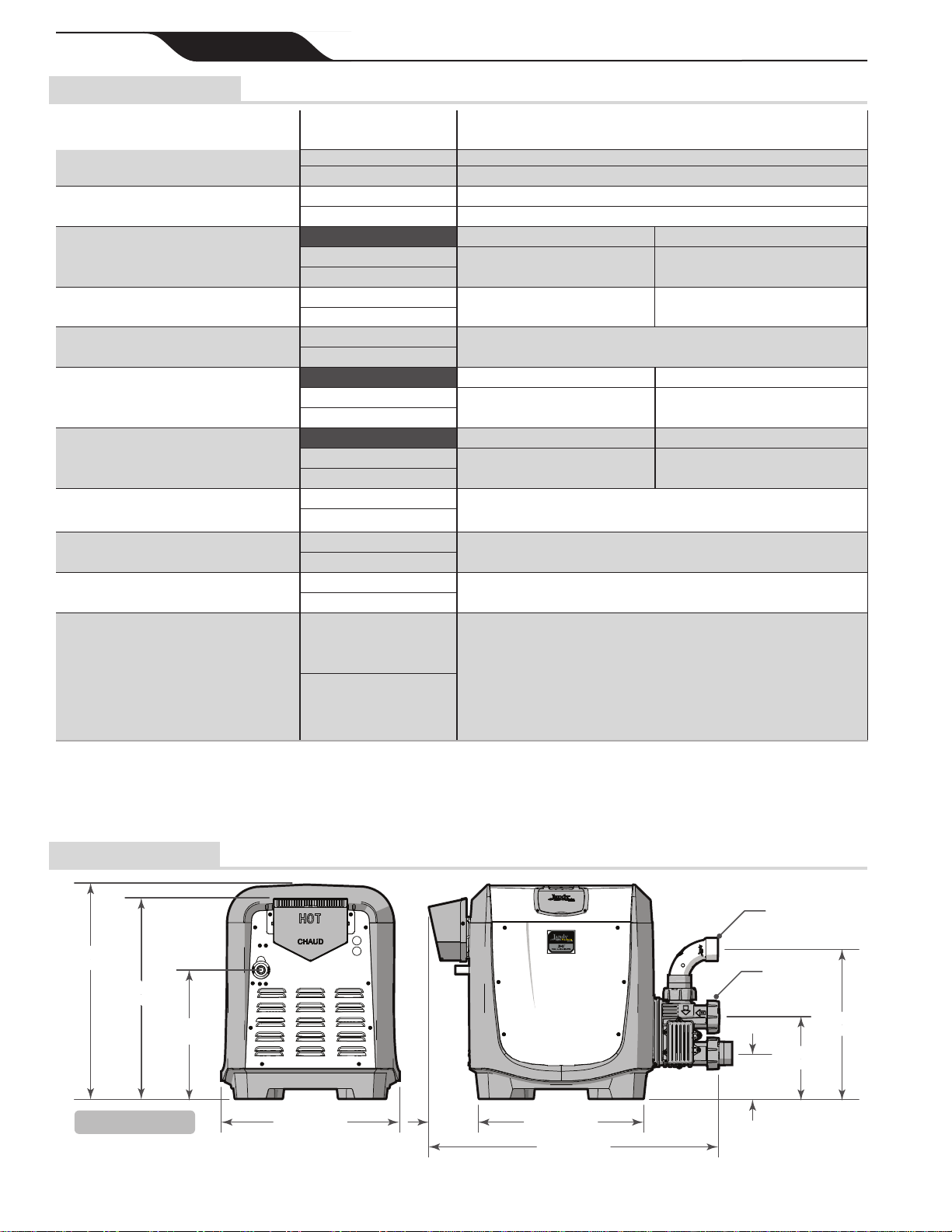
1.6 Dimensions......................................................... 4
1.7 CerticationCodesandStandards..................... 5
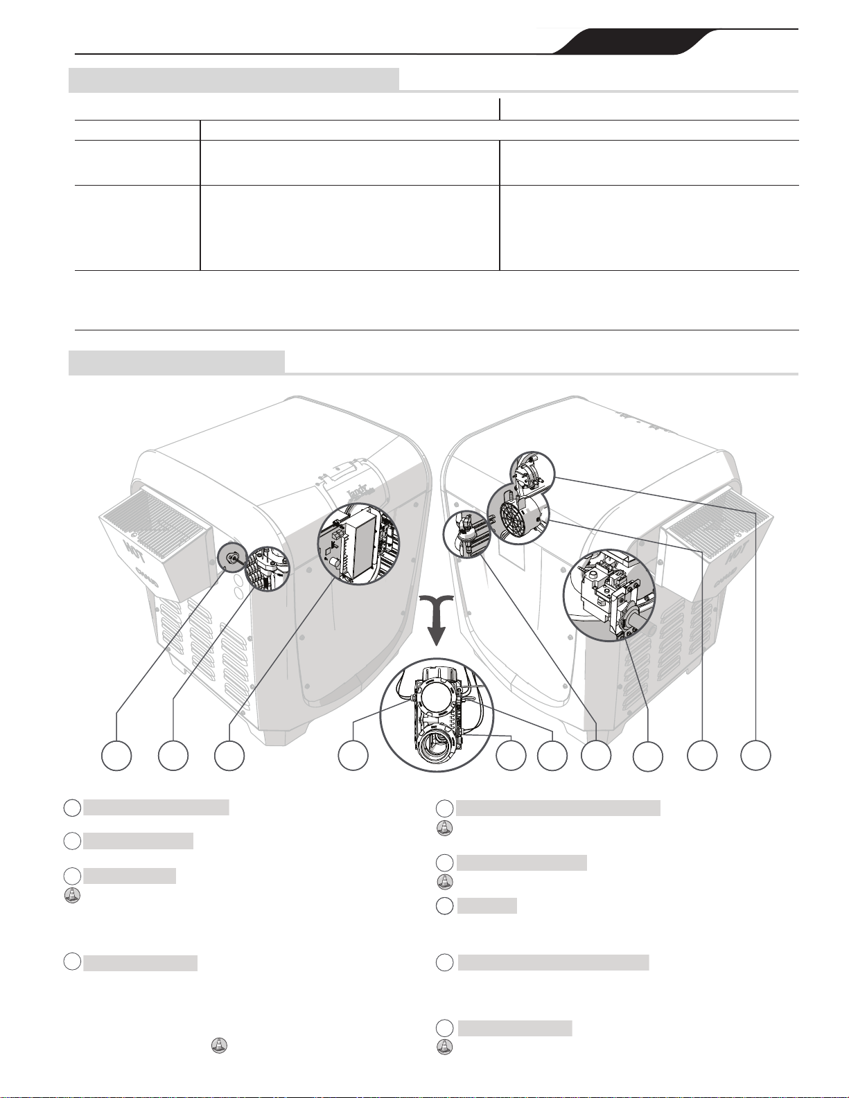
1.8 Heater Components........................................... 5
Section 2. Getting Started................................ 6
2.1 Package Contents.............................................. 6
2.2 Required Equipment........................................... 7
2.2.1 Tools................................................................................... 7
2.2.2 Materials............................................................................. 7
Section 3. Location Requirements.................. 8
3.1 Clearances......................................................... 8
3.2 Outdoor Installation............................................ 9
3.2.1 Anchor Bracket Installation............................................... 10
3.3 Indoor and Outdoor Shelter Installation.............11
3.3.1 Combustion IntakeAir Supply...........................................11
3.3.2 Exhaust Venting ............................................................... 12
3.3.3 Indoor and Outdoor Shelter Exhaust Conversion............. 13
3.3.4 Indoor and Outdoor Shelter Exhaust Termination............ 14
3.3.5 PrecautionsAgainst Common Venting............................. 14
3.3.6 Inspection and Replacement
of Existing Vent System with New Components............... 14
Section 4. Gas Connections.......................... 15
4.1 Supply Gas Requirements ............................... 15
4.2 Inlet Gas Pressure Test.................................... 16
4.3 Gas Offset Pressure Test ................................. 16
4.3.1 Connect the Digital Differential Manometer...................... 17
4.3.2 Gas Offset Pressure Adjustment...................................... 17
4.4 Special Precautions for LP Gas........................ 18
Section 5. Water Connections....................... 18
5.1 Pump Sizing..................................................... 19
5.1.1 Manual Bypass Valve....................................................... 19
5.1.2 Pump Sizing for New Pool Construction:......................... 19
5.1.3 Pump Sizing for Replacement in an Existing Pool:.......... 19
5.2 Plumbing Connections ..................................... 20
5.2.1 Reversing Plumbing Connections.................................... 20
5.2.2 Optional Water Inlet Piping............................................... 20
5.3 Water Pressure Switch Adjustment.................. 21
5.4 Check Valve Installation................................... 22
5.5 Pressure Relief Valve Installation..................... 22
5.5.1 Install pressure relief valve kit # R0336101...................... 22
5.6 Auxiliary Components, Chlorinators,
Ozone Generators, and Sanitizing Chemicals . 23
Section 6. Electrical Connections................. 24
6.1 Service Access................................................. 25
6.2 Main Wiring Connections ................................. 25
6.3 Input Voltage and Conversion.......................... 25
6.4 Bonding............................................................ 26
Section 7. Optional Remote Controls........... 26
7.1 Connecting to a Remote Pool-Off-Spa Selector
(3-Wire Connection)......................................... 27
7.1.1 ConguretheControlPanel:............................................ 27
7.2 Connecting to an AquaLink® Control System
or Remote TSTAT (2-Wire Connection)............ 27
7.2.1 Install the Remote TSTAT:................................................ 27
7.2.2 ConguretheControlPanel:............................................ 27
7.3 “Smart” Communication via RS-485 ................ 28
7.3.1 To Restore Heater Control Panel Functionality
After Connecting to an External Controller.................................... 29
7.3.2 To return functionality to RS:............................................ 29
Section 8. Operating Instructions................. 29
8.1 IMPORTANT SAFETY INFORMATION............ 29
8.1.1 WHAT TO DO IF YOU SMELL GAS................................. 29
8.2 First-Time Start-Up Procedure ......................... 29
8.2.1 OPERATING INSTRUCTIONS ........................................ 30
8.2.2 If Ignition Is Unsuccessful................................................. 30
8.3 TO TURN OFF GAS TO THE HEATER ........... 30
8.4 Normal Operation............................................. 30
8.5 Operating the Controller................................... 32
8.5.1 Setting up Heater Options................................................ 32
8.5.2 Operating the Heater........................................................ 33
8.6 Shutting Down the Heater................................ 33
Section 9. Maintenance.................................. 34
9.1 Water Chemistry............................................... 34
9.1.1 Saturation Index............................................................... 34
9.2 Swimming Pool Energy Saving Tips................. 35
9.3 Winterizing........................................................ 35
9.4 Spring Start-up................................................. 35
9.5 Inspection and Service..................................... 36
9.5.1 Guidelines for Homeowner Inspection:............................ 36
9.5.2 Guidelines for Professional Inspection:............................ 36
Section 10. Troubleshooting ........................... 37
10.1 Common Problems........................................... 37
10.2 Service Diagnostic Messages.......................... 38
10.3 Ignition Control LED Service Codes................. 38
Section 11. Professional Service
and Maintenance .......................... 39
Section 12. Spare Parts.................................... 39
12.1 Major Components........................................... 39
12.2 Cabinet Assembly Spare Parts List
and Exploded Parts Diagram ........................... 40
12.3 Heat System Spare Parts List
and Exploded Parts Diagrams.......................... 41
12.3.1 Combustion Chamber Assembly...................................... 41
12.3.2 Burner Assembly.............................................................. 42
12.4 Water System Spare Parts List
and Exploded Parts Diagrams.......................... 43
12.5 Electrical System Spare Parts List
and Exploded Parts Diagrams ......................... 44

Page 3
ENGLISH
Jandy®Pro Series, JXi™Gas-Fired Pool & Spa Heater |Installation & Operation Manual
Section 1. General Information
This manual provides installation and operation
instructions for the Jandy Pro Series JXi pool and spa
gas heater product line.
Read the installation and operation instructions
completely before proceeding with the
installation.
1.1 Technical Assistance
Web: www.jandy.com Phone: 800.822.7933
1.2 Warranty
This heater is sold with a limited factory warranty.
Details are included with this heater.
Make all warranty claims to a Zodiac®dealer or directly
to the factory. Claims must include the heater serial
number and model (this information can be found on the
rating plate), installation date, and name of the installer.
Shipping costs are not included in the warranty coverage.
The warranty does NOT cover damage caused by
improper assembly, installation, operation or eld
modication. Also, damage to the heat exchanger by
corrosive water is NOT covered by the warranty.
NOTE: Keep this manual in a safe place for future reference when
inspecting or servicing the heater.
1.3 Consumer Information and Safety
The heater is designed and manufactured to provide
many years of safe and reliable service when installed,
operated, and maintained according to the information
in this manual and the installation codes referred to
throughout. Be sure to read and comply with all warnings
and cautions.
WARNING
Improper installation or maintenance can cause nausea or asphyxi-
ationfromcarbonmonoxideinuegaseswhichcouldresultin
severe injury, or death. For indoor installations, as an additional
measure of safety, Zodiac Pool Systems, Inc. strongly recom-
mends the installation of suitable Carbon Monoxide detectors in
the vicinity of this appliance and in any adjacent occupied spaces.
WARNING
The following “Safety Rules for Hot Tubs,” recommended by the
U.S. Consumer Product Safety Commission, should be observed
when using the spa. Consult heater operation and installation
instructions for water temperature guidelines before setting tem-
perature.
• Spa or hot tub water temperature should never exceed 104°F
(40°C). One hundred degrees Fahrenheit (100°F [38°C]) is consid-
ered safe for a healthy adult. Special caution is recommended for
young children.
• The drinking of alcoholic beverages before or during spa or
hot tub use can cause drowsiness which could lead to uncon-
sciousness, and subsequently result in drowning.
• Pregnant women take note! Soaking in water above 102°F
(38.5°C)cancausefetaldamageduringtherstthree(3)months
of pregnancy (which could result in the birth of a brain-damaged or
deformed child). If pregnant women are going to use a spa or hot
tub, they should make sure the water temperature is below 100°F
(38°C) maximum.
• The water temperature should always be checked with an ac-
curate thermometer before entering a spa or hot tub. Temperature
controls may vary by as much as 1F°/1C°.
• Persons with a medical history of heart disease, diabetes, cir-
culatory or blood pressure problems should consult their physician
before using a hot tub or spa.
• Persons taking any medication which induces drowsiness
(e.g., tranquilizers, antihistamines, or anticoagulants) should not
use spas or hot tubs.
• Prolonged immersion in hot water can induce hyperthermia.
• Hyperthermia occurs when the internal body temperature
reaches a level several degrees above the normal body tem-
perature of 98.6°F (37°C). Symptoms include dizziness, fainting,
drowsiness, lethargy, and an increase in the internal body tempera-
ture. The effects of hyperthermia include:
• Lack of awareness of impending hazard
• Failure to perceive heat
• Failure to recognize need to leave spa
• Physical inability to leave spa
• Fetal damage in pregnant women
• Unconsciousness resulting in a danger of drowning
1.4 General Operation Description
The blower draws air and fuel through specially designed
orices, delivering a precise mixture to the burner,
located inside the sealed combustion chamber. Water
ows through the heat exchanger, which surrounds the
burner transferring the heat to the water. Exhaust gases
are then directed through a duct where it is vented to the
atmosphere.

Page 4 ENGLISH Jandy®Pro Series, JXi™Gas-Fired Pool & Spa Heater |Installation & Operation Manual
1.5 Speci cations
SUPPLY GAS
INSTALLATION LOCATION* NATURAL GAS (NG) CERTIFIED INDOOR/OUTDOOR
LIQUID PROPANE (LP) CERTIFIED INDOOR (US ONLY) / OUTDOOR / COVERED SHELTER
GAS PIPE HEATER GAS VALVE
CONNECTION†
NATURAL GAS (NG) 3/4” NPT
LIQUID PROPANE (LP) 3/4” NPT
INLET GAS SUPPLY PRESSURE
Min Max
NATURAL GAS (NG) 4.0” WC 14.0” WC
LIQUID PROPANE (LP)
GAS VALVE OFFSET PRESSURE‡NATURAL GAS (NG) .2” WC .2” WC
LIQUID PROPANE (LP)
WATER PIPE/HEATER CONNECTION NATURAL GAS (NG) • PVC/CPVC 2” unthreaded
• Jandy Pro Series threaded union
LIQUID PROPANE (LP)
WATER FLOW RATE
Min Max
NATURAL GAS (NG) 30 gpm
(76 lpm) 100 gpm
(454 lpm)
LIQUID PROPANE (LP)
WORKING WATER PRESSURE
Min Max
NATURAL GAS (NG) 2 psi 50 psi
LIQUID PROPANE (LP)
EXHAUST VENT CONNECTION SIZE
(CATEGORY I)§
NATURAL GAS (NG) • Model 200: 6 "
• Model 260: 7 "
• Model 400: 8 "
LIQUID PROPANE (LP)
EXHAUST VENT CONNECTION SIZE
(CATEGORY III)
NATURAL GAS (NG) See Section 3.3.2
LIQUID PROPANE (LP)
ELECTRICAL SUPPLY NATURAL GAS (NG) • 120 VAC
• 240 VAC
LIQUID PROPANE (LP)
HIGH ALTITUDE
NATURAL GAS (NG) Appliances are normally derated when installed at high elevation. This is
not necessary with the JXi heater because it has a special venturi-type
combustion system which self-compensates for changes in barometric
pressure.Airowthroughtheblowerinletpullsthecorrectowofgasinto
the burner regardless of air density.
JXiheatersareCSAcertiedforelevationsofupto4,500feetabovesea
level. At elevations above 4,500 ft., the heater BTU output can be expected
to be reduced by 4% for every 1,000 feet over 4,500 feet above sea level.
LIQUID PROPANE (LP)
* Indoor installation is not recommended for liquid propane heaters.
Review Special Precautions for liquid propane heaters (Section 4.4)Anychangestotheheater,gascontrols,airorice,gasorices,wiring,or
improper installation may void the warranty. If change is required to any of
the above; contact your local Jandy distributor, visit www.jandy.com or call
technical support at 800.822.7933.
†For gas pipe size requirements see Section 4
‡ All readings must be taken while the heater is operating
§ Use type B double-wall gas vent, per table 13.1(a) NFPA 54
1.6 Dimensions
Figure 1. General Dimensions
Dimensions are identical
for all heater models 22.1" (56 cm)
24.9"
(63 cm)
16"
(40.6 cm)
21.6" (55 cm)
5.1"
(13 cm)
5.6"
(14 cm)
10.13”
(26 cm)
18.5”
(47 cm)
5.6"
(14 cm)
10.13"
(26 cm)
Versa Plumb® Inlet
18.5"
(47 cm)
35.4" (90 cm)
26.5"
(67 cm)
22.1" (56 cm)
24.9"
(63 cm)
16"
(40.6 cm)
21.6" (55 cm)
35.4" (90 cm)
26.5"
(67 cm) Inlet

Page 5
ENGLISH
Jandy®Pro Series, JXi™Gas-Fired Pool & Spa Heater |Installation & Operation Manual
1.7 Certi cation Codes and Standards
USA CANADA
DESIGN CERTIFIED CSA (Canadian Standards Association)
COMPLIANT ANSI® Z21.56
California South Coast Air Quality Management
District’s (SCAQMD) Rule 1146.2 CSA 4.7
NATIONAL CODES
National Fuel Gas Code Natural Gas and
Propane Installation Code
NFPA® 54/ANSI Z223.1 CAN/CSA-B149.1
Pay particular attention to the chapter addressing
Venting of Equipment Minimum combustion air requirements MUST be followed
for proper and safe operation. Failures may occur when
only the minimum combustion air openings are used.
All Jandy Pro Series heaters must be installed in accordance with the local building and installation codes as per the utility or Authority Having
Jurisdiction (AHJ). In the absence of local codes, please refer to the latest edition of the national codes for installation.
JXi pool and spa heaters meet or exceed the requirements of energy conservation regulations such as those in states that have disallowed the
use of continuously lit pilot type ignition sources.
1.8 Heater Components
Front
Rear
Header
a
Monitors temperature at the exhaust flue. If
excessive temperatures are detected,
combustion will stop and a fault will be displayed.
Flue Temperature Sensor
a
Indicates a safety control equipped to protect internal
components and extend the life of the heater.
bcdd efghi
Controls gas flow into the burner. Enables flow when the
temperature control calls for heat and all safety controls
enable operation. It also regulates gas pressure to -2” WC (Water Column)
below the air pressure at the blower inlet. Necessary pressure regulation
cannot be accomplished with common (positive pressure) gas valves.
Gas Valve
g
When current is passed through the ceramic
material of the igniter it will achieve temperatures
great enough to initiate combustion of the air/fuel mixture.
Hot Surface Igniter
b
Provides energy for ignition, monitors flame quality
and controls the gas valve. Upon call for heat, the
blower is activated to purge the combustion chamber. Electrical power is
then applied to the hot surface igniter. When ignition temperature is
attained, the gas valve opens and ignition occurs. If stable flame is detected
the igniter will power down. If stable flame is not detected the control
system will close the valve to prevent further gas release. If a total of 3
ignition attempts fail an ignition fault is displayed.
Ignition Control
c
Prevent water of excessive temperatures from
being discharged from the heater. If either switch,
one at the heat exchanger first pass 57°C and one at the heat exchanger
outlet 65°C, senses excessive temperature, the gas valve will close and
combustion will stop.
High Limit Switches
d
Senses water temperature by
means of a thermistor. Heater
will operate to attain and maintain the water temperature according to the
heater settings. Two separate thermostat settings are supported, typically
used to set pool and spa temperatures.
Pool/Spa Water Temperature Control
e
Senses whether or not water is available to
the heater by measuring back pressure at the
header inlet. If insufficient pressure is detected, the display will indicate a
“Check Flow” fault and combustion will stop.
Water Pressure Switch
f
Draws in air and fuel gas
creating an air/fuel mixture that
is passed through the burner for combustion. The fan will operate for
several seconds before flame initiation and after the flame is extinguished
to purge the combustion chamber for a clean burn and to expel any
residual exhaust gas.
Combustion Blower and Air Orifice
h
Monitors the vacuum (negative pressure) within
the blower housing. This switch verifies that air is
flowing through the combustion system by sensing pressure. If air flow is
inadequate, combustion will stop and a fault will be displayed.
Air Pressure Switch
i

Page 6 ENGLISH Jandy®Pro Series, JXi™Gas-Fired Pool & Spa Heater |Installation & Operation Manual
Section 2. Getting Started
Install the JXi in accordance with the procedures in this
manual, local codes and ordinances, and in accordance
with the latest edition of the appropriate national code.
See Section 1.7.
If the heater is to operated in below freezing conditions it
should be installed in a protected outdoor shelter.
See Section 3.3
All gas- red products require correct installation to
ensure safe operation. The requirements for pool heaters
include the following:
• Field assembly (if required)
• Appropriate site location, clearances and ooring
see Section 3
• Suf cient combustion and ventilation air
• Properly sized gas meter and piping
• Proper electrical wiring
• Suf cient water ow
This manual provides the information needed to
meet these requirements. Review all applications and
installation procedures before continuing the installation.
2.1 Package Contents
Before completely unpacking the unit please inspect
carton for damage. In addition please check the carton label to ensure that you have the correct fuel type and
BTU rating for your application.
JXI400N
DIRECT IGNITION
E15XJ1000
399,000
JXI, US
CSA Certified for installations up to 4,500 FT (1,372m), BTU output
is reduced about 4% per 1000 ft (305 m) over 4,500 ft (1,372m). In
general efficiency is not affected by altitude.
ALTITUDE:
JXI400N
DIRECT IGNITION
E15XJ1000
399,000
JXI, US
JXI400P
DIRECT IGNITION
E15XJ1232
399,000
JXI, US
CSA Certified for installations up to 4,500 FT (1,372m), BTU output
is reduced about 4% per 1000 ft (305 m) over 4,500 ft (1,372m). In
general efficiency is not affected by altitude.
ALTITUDE:
1
2
3
4
5
6
NOTE:
1 EA of item 4, item 5 and
item 6 will come pre-installed at
the horizontal manifold inlet.
Item Description Qty.
1 JXi Heater 1
2 VersaPlumb Sweep Elbow 1
3 2” Universal Union Tailpiece 2
Item Description Qty.
4 2” Universal Union Cap 1
5 2” Universal Union O-ring 3
6 2” Universal Union Nut 3
OR

Page 7
ENGLISH
Jandy®Pro Series, JXi™Gas-Fired Pool & Spa Heater |Installation & Operation Manual
2.2 Required Equipment
Please ensure that the following equipment is available to the installer at the time of installation.
2.2.1 Tools
Safety Eyewear Gloves Phillips
Screwdriver Flathead
Screwdriver Pipe Wrench
Adjustable
Wrench 3/16” Hex Key Channel Locks Digital
Differential
Manometer
Voltage Meter PVC Pipe Cutter Power Drill Tape Measure
2.2.2 Materials Supplied by Installer
Please ensure that all materials used during the
installation are in accordance with local codes or the
authority having jurisdiction (AHJ) requirements. If you
have any questions regarding the materials that need to
be used during this installation please call the Zodiac
customer service center at 1-800-822-7933.
Indoor installations will require additional venting and
exhaust conversion materials which are outlined in detail
in Section 3.3
NOTE: Required materials may differ from the materials listed. Be
suretoconrmwithalllocalandnationalcodesbeforebeginningthe
installation.
GAS SUPPLIES ELECTRICAL
SUPPLIES PLUMBING
SUPPLIES
Appropriately sized Gas
Piping (see Section 4.1) 120 or 240 VAC PVC Piping
Manual Gas Shut Off Valve Conduit Elbow/
Conduit connector. PVC Cement
Gas Union Flexible Conduit TeonTape
Cap Wire Nuts
Leak Solution
1/16” Hose “T”
1/8” - 1/16” Barbed Adapter
1/16” Flexible Hose

Page 8 ENGLISH Jandy®Pro Series, JXi™Gas-Fired Pool & Spa Heater |Installation & Operation Manual
Section 3. Location Requirements
The JXi heater is shipped from the factory with an
exhaust vent con gured for outdoor installation. The
heater is also design-certi ed for indoor installations in
the United States and for outdoor shelter installations in
Canada. See Section 3.3 for details.
Location of the heater below or above the pool water
level affects operation of its water pressure switch. See
sections 5.3 for more information.
NOTE: If the heater is to be operated in below freezing conditions it
should be installed in a protected outdoor shelter.
CAUTION
When pool equipment is located below the pool surface, a leak from
anycomponentcancauselargescalewaterlossorooding.Zodiac
Pool Systems, Inc., cannot be responsible for such water loss or
oodingorresultingdamage.
3.1 Clearances
The heater must be installed in a location that allows
clearances for maintenance and inspection. Minimum
distances from combustible surfaces must also be
maintained. All criteria given in the following sections
re ect minimum clearances as stated in the national
standards. However, each installation must also be
evaluated, taking into account prevailing local conditions
such as wind speed and direction, proximity and height of
obstructions that may block ventilation, and proximity to
public access areas.
Service Clearance: 36 inches (45 cm) from top of heater
for removal of top panel.
18 inches in the us and 24 inches (30 cm) in Canada from
one of either the front or rear panels.
Combustible Surfaces: Each heater face requires a
6 inch (15 cm) clearance from combustible surfaces.
Although it is not advisable, the heater base can be placed
on a combustible surface for operation. However, do not
install the heater on carpet.
Figure 2. Clearances
required per CSA B149.1, section 4.14.2.
Combustible
Surface
6 in (15 cm)
Service
Clearance
TOP: 36 in (45 cm)
FRONT: 18 in (22.5 cm) USA
24 in (30 cm) Canada
NOTE:
Clearances are manufacturer’s
tested values. These are given as minimum
values. Where local and national codes
apply, and if the clearance values specified
in the applicable codes are different than
those listed in this manual, use the greater
value to ensure safest operation.

Page 9
ENGLISH
Jandy®Pro Series, JXi™Gas-Fired Pool & Spa Heater |Installation & Operation Manual
3.2 Outdoor Installation
Locate the heater:
• On a level Solid Surface
• 5 ft (1.5 m) from inner pool edge unless separated by
a permanent solid barrier, i.e. a wall or fence
• In an open area, not under a deck or other structure
• Away from doors windows or louvers that connect
in any way to occupied or inhabited areas of the
building.
NOTE: In Canada the top of the exhaust vent must be at least 10
feet (3 m) from any building opening..
• Away from rainwater runoff
• Away from potential sprinkler water intrusion
• So that the top of the heater is at least 3 feet (1 m)
below any overhang
• So that the top surface of the heater is at least 3 feet
(1 m) above any forced air inlet within 10 feet (3 m)
Figure 3. Location Requirements
min. 5 ft (1.5 m)min. 5 ft (1.5 m)
unless the heater is
separated from the pool by
a solid fence, wall or other
permanent solid barrier.
Locate the heater on a level surface in an open, unroofed area.
Do not install the heater under a deck.
The heater must be installed on a level, solid, and firm surface or platform.
Although it is always advisable to install the heater on a non-combustible
surface, the JXi-series has been CSA-certified for installation on solid,
firm, and level combustible surfaces. DO NOT INSTALL ON CARPET.
Do not locate the heater
below or adjacent to any
doors, windows, louvers,
grills, etc., which connect
in any way with an
inhabited area of a
building, even though the
access might be through
another structure (e.g., a
garage or utility room).
If the heater is installed close to a structure, protect it from rain water runoff
with rain gutters on the roof or other measures.
Be sure to divert rain water runoff away from heater
The area under an
overhang must be
open on three sides to
prevent combustion
gases from being
diverted into living
areas through doors,
windows, or gravity
inlets
In the United States install the heater so that there is at least a
three (3) foot (1 m) clearance between the bottom of the
overhang to the top of the heater exhaust vent.
Do not install the heater with the top of the vent assembly within 4 feet (1.22
m) horizontally, 4 feet (1.22 m) below or less than 1 ft (300 mm) above of any
opening into a building. Local codes and installation requirements may vary.
In Canada, install the heater so that the top of the vent is at least
10 feet (3.0 m) from any building opening.
The top surface of the heater must be at least 3 feet (1 m) above any forced
air inlet, or intake ducts located within 10 feet (3.0 m) horizontally
Do not locate the heater near sprinkler
systems that could spray water on it.
Water from sprinklers can damage
controls and electronic components.
WARNING
United States
Do not install the heater with the top of the vent assembly within 4 feet
(1.22 m) horizontally, 4 feet (1.22 m) below or less than 1 ft (300 mm)
above of any opening into a building. Local codes and installation
requirements may vary.
Canada
Do not install the heater with the top of the vent assembly within
10 feet (3.0 m) of any opening into a building. Local codes and
installation requirements may vary.

Page 10 ENGLISH Jandy®Pro Series, JXi™Gas-Fired Pool & Spa Heater |Installation & Operation Manual
a
c
d
b
e
f
Anchor Bracket Upper
Anchor Bracket Lower
Concrete Equipment Pad
ANCHOR BRACKET INSTALLATION
SECTION VIEW
Concrete Screw
JXi™ Heater Base
Anchor Bracket Slot
Retaining Nut
Retaining Pin
3.2.1 Anchor Bracket Installation
Anchor brackets do not come standard with the JXi if you
require the anchor brackets for your installation please
order kit #R0593400.
Anchor brackets should be installed in any circumstance
where the heater may be subject to natural risks such as
extreme weather or earthquake. In Florida, the heater is
required to be securely fastened to the equipment pad to
meet the applicable requirements of the Florida Building
Code. Other jurisdictions may have similar requirements
for extreme weather or other natural hazards. Check your
local codes for details.
a
Using an adjustable wrench or equivalent tool loosen
(DO NOT REMOVE) the retaining nut on the bracket.
The upper and lower anchor bracket should be able to
rotate freely about the retaining pin.
b
Slide the bracket into the slot located at the lower
corner of the heater base.
c
Rotate lower anchor bracket into nal position.
Ensure that the lower anchor bracket is ush with the
equipment pad surface and level.
d
Tighten the retaining nut so that the anchor bracket
assembly is secure.
e
Drill a hole in the concrete using the lower anchor
bracket hole as a guide. It is advised that a hammer drill
with an appropriate concrete drill bit be used.
f
Place a screw in the hole and tighten to fasten the
anchor bracket to the concrete pad. Do not over torque
the screws.
NOTE: Depending on the location of and access to the bracket, it
may be necessary to mark the drill location using the lower anchor
bracket hole as a guide. Remove the bracket from the heater, drill
the hole and then reattach the bracket to the heater base.
NOTE: Concrete screws are not provided in the anchor bracket
kit. Use size 1/4” x 2-1/4” galvanized or plated concrete screws and
washers.

Page 11
ENGLISH
Jandy®Pro Series, JXi™Gas-Fired Pool & Spa Heater |Installation & Operation Manual
3.3 Indoor and Outdoor Shelter Installation
Due to the higher risks and hazards of liquid propane
(LP) gas, Zodiac®does not encourage installation of LP
gas heaters indoors. Please be sure to refer to Section 4.4.
The heater is CSA design-certi ed for indoor installations
in the US and for outdoor shelter installations in Canada.
Please keep in mind the service and combustible
surface clearances from Section 3.1 when selecting
an installation location. You will also need to make
considerations for intake combustion air see Section 3.3.1
and exhaust venting see Section 3.3.2. In addition,
when pool equipment is installed indoors, appropriate
containment measures and drains should be considered
for the prevention of property damage in the event of an
equipment leak.
NOTE: An outdoor shelter is an unoccupied enclosure which does
not communicate directly with occupied areas.
Zodiac Pool Systems, Inc., does not recommend US outdoor
shelter installations that depend on internal air for combustion.
3.3.1 Combustion Intake Air Supply
Figure 4. Indoor and Outdoor Shelter Installation
Minimum pitch
per 12 in. of pipe:
1/4 in (6.35 mm)
JXi 200 50 in2
323 cm2
65 in2
419 cm2
100 in2
645 cm2
JXi 260
JXi 400
Minimum Net Free Open Area*
Combustion Openings
Horizontal Duct
4
2
1.5Screens or Metal Louvers
Wood Louvers
Multiply required
opening above by*if air passes through:
In Canada the
installation must
be in accordance
with the latest edition
of CAN/CSA B149.1.
All outdoor
shelter and
indoor
installations
must have
uninterrupted
openings to
outside air for
combustion and
ventilation. Do
not, under any
circumstances,
install this
product in an
indoor location
which does not
provide
combustion air
to the appliance
from outside
the building.
For garage installation, heater base must be 18 in (46 cm) above the floor.
Within 12 in. (30.5 cm)
Listed Vent Cap
Use Approved Rook Jack
Storm Collar
Within 12 in. (30.5 cm)
2 ft. (61 cm) Min.
Height required
for any roof surface
within 10 ft. ( 3m) 3 ft. (91.5 cm) Minimum
Above Highest Outlet Point
10 ft. (3 m)
Greater Than 10 ft. (3 m)
As outlined in the latest edition of ANSI®
standard Z223.1 (NFPA® 54), the heater
location must be properly vented to provide
suf cient air supply for proper combustion.
When combustion air is supplied directly
through an outside wall, each opening
should have a minimum free area of 1 square
inch per 4,000 BTU/h (1.2 kW) input of
the total input rating of all appliances in
the enclosed area. If combustion air must
pass through horizontal ducts, each opening
should have a minimum free area of 1 square
inch per 2,000 BTU/h (1.2 kW) input of
the total input rating of all appliances in
the enclosed area. Details can be found in
Figure 4.
The “Minimum Net Free Open Area”
information from Figure 4 is not applicable
in installations where exhaust fans
or blowers of any type are used. Any
equipment which exhausts air from the room
where the heater is installed can deplete the
combustion air supply or reverse the natural
draft action of the venting system. This
could cause ue products to accumulate in
the room. Additional air must be supplied
to compensate for such exhaust. Consult
a professional engineer to ensure that
installations where exhaust fans or blowers
are used are designed and installed in
accordance with all applicable local and
national installation codes.
In addition, the heater must be completely
isolated and protected from any source
of corrosive chemical fumes or corrosive
vapors (i.e chlorine or hydrochloric acid).
WARNING
Do not store any chemicals, cleaners, or other
corrosive material near combustion air openings
or in the room. Avoid locating appliance vents in
the vicinity of combustion air openings. Failure
to prevent corrosive materials from mixing with
combustion air can result in reduced heater life
and unsafe heater operation.

Page 12 ENGLISH Jandy®Pro Series, JXi™Gas-Fired Pool & Spa Heater |Installation & Operation Manual
3.3.2 Exhaust Venting
When the JXi heater is installed indoors or in an outdoor
shelter it can be vented as a Category I or Category III
appliance. In either case the vent pipe sizing must be in
accordance with the specications listed in Table 1.
• Category I: Appliance operates with a negative vent
static pressure, a vent gas temperature that avoids
excessive condensate production and will vent
vertically terminating at the roof.
• Category III: Appliance operates with a positive
vent static pressure, a vent gas temperature that
avoids excessive condensate production and can be
vented horizontally terminating at a side wall.
• Do not terminate heater vents near air conditioning
or air supply fans which could pick up exhaust
ue products, such as carbon monoxide and other
hazardous efuent, and return them inside the building.
• Vent pipe type and material must be carefully
selected and depends on the type of installation.
• Do not locate the vent terminal where exhaust ue
products could strike against building materials and
cause degradation.
• Vent opening should be well away from landscaping
or other obstructions that would prevent free air ow
to and from vent terminal.
• Do not terminate vent under decks, stairs, or car ports.
• Do not use the appliance to support the vent pipe.
• Vent piping must be supported with no low spots or
sagging which could allow condensate to collect.
• Horizontal runs must be sloped upwards away from
the heater to a vent terminal at a minimum of 1/4" per
horizontal foot (2 cm/m). See Figure 4.
• Install the vent pipe so it can expand and contract
freely with temperature changes.
• Do not run the heater vent into a common vent with
any other appliance.
• It is recommended that vent runs over 18 feet
be insulated to reduce condensation and use a
condensate trap in the vent run close to the heater,
especially in cold climate installations.
WARNING
Vent pipe materials, sizing, and installation must be as required
by the National Fuel Gas Code NFPA 54/ANSI® Z223.1 or the
Canadian Installation Codes for Gas Appliances CAN/CSA-B149.1.
Undersized pipe can result in inadequate venting and oversize pipe
can result in vent condensation. Improper selection of vent pipe
material, incorrect sizing of the pipe, and incorrect installation of vent
piping can result in release of combustion products to the indoors.
This can cause serious injury or death by Carbon Monoxide poison-
ing or asphyxiation.
WARNING
Improper installation or maintenance can cause nausea or asphyxia-
tionfromcarbonmonoxideinuegaseswhichcouldresultinsevere
injury or death. For indoor installations, as an added measure of
safety, Zodiac Pool Systems, Inc. strongly recommends installation
of suitable carbon monoxide detectors in the vicinity of this appliance
and in any adjacent occupied spaces.
Incorrect design and installation of heater vents and ducts can result
in personal injury, damage to property, or death. To avoid such
hazards,theheatermustbeinstalledonlybyaqualiedprofessional
service technician.
CODES*
National Fuel Gas code ANSI® Z223.1 (NFPA®54)
CAN/CSA-B149.1
CATEGORY STATIC
PRESS. STACK
TEMP. CONDENSATE TERMINATION
LOCATION
PIPE SIZING
MODEL PIPE SIZE SPECIAL GAS VENT LENGTH†
(VERTICAL OR HORIZONTAL)
INegative High Minimal Roof
200 6 in (15 cm) N/A
260 7 in (18 cm) N/A
400 8 in (20 cm) N/A
III Positive High Minimal Roof or Side
Wall
200 4 in (10 cm) 50 ft (15 m)
260 4 in (10 cm) 70 ft (21 m)
400 4 in (10 cm) 70 ft (21 m)
*Ensure that you are referencing the latest edition and pay special attention to the chapter addressing “Venting of Equipment”.
†For each elbow installed, reduce the run length by 12 feet (3.7m)
Table 1. Vent Pipe sizing Requirements

Page 13
ENGLISH
Jandy®Pro Series, JXi™Gas-Fired Pool & Spa Heater |Installation & Operation Manual
3.3.3 Indoor and Outdoor Shelter Exhaust Conversion
For both Category I and Category III vent types the
heater must rst be converted to indoor exhaust type. In
order to complete the conversion you will need to order
exhaust conversion R-Kit R0711900.
a
Remove two screws securing the exhaust grill to the
exhaust grill backplate.
b
Remove exhaust grill.
c
Remove the two screws securing the rain shield to
the exhaust backplate.
d
Remove Rain Shield.
e
Remove the remaining two screws securing
the exhaust backplate to the exhaust outlet.
f
Remove the exhaust grill backplate.
g
Using two #10 thread cutting screws secure
the vent adapter from R-Kit R0711900 to the
exhaust outlet.
h
If venting for Category I, install an
appropriate vent pipe increaser to accommodate
the correct pipe size from Table 1. Secure to the
vent adapter using the screw clamp.
When the installation requires horizontal venting
in excess of what is allowed for Category I
installations or calls for horizontal discharge, the
JXi may be installed with a Category III venting
system.
Vent the heater either vertically
or horizontally using Al29-4C
stainless steel components. Consult
manufacturers such as Z-Flex®
or Heat Fab®to obtain approved
components. Venting materials
must comply with UL® 1738 for
Category III, Special Gas Vent. In
Canada, the venting materials must
be ULC S636 compliant.
i
If venting for Category III,
install appropriate vent pipe
from Table 1. Secure to the vent
adapter using the screw clamp to
ensure a proper seal.
Double check that there are no possible leak paths
between joints. If a leak path is identi ed or suspected
it can be sealed using red RTV 600° F rated silicone
adhesive.
When using parts or materials from other manufacturers
please be sure to follow the manufacturers instructions
completely to ensure harmonious function.
IMPORTANT NOTE
In the Commonwealth of Massachusetts, additional requirements, covered in document CMR 248 5.00, which supersede some of the require-
ments of ANSI Z223.1 (NFPA 54) apply to Side Wall Horizontally Vented appliances. If installing this product using an approved side-wall hori-
zontal vent system in the Commonwealth of Massachusetts, be sure to adhere to these additional requirements. These requirements include
verbiage that says that the property owner is to ensure that Carbon Monoxide Detectors are installed in the vicinity of the appliance and also on
all levels of the dwelling in which the appliance is installed.
For further instructions, contact Technical Support at 800.822.7933.
i
g
h
Vent Elbow
for Category I
OR
for Category III
Increaser
4" Vent Pipe
Vent Adapter
Exhaust Outlet
e
b
f
c
d
Exhaust Grill
Exhaust Grill Backplate
Rain Shield
Exhaust Outlet
a
a

Page 14 ENGLISH Jandy®Pro Series, JXi™Gas-Fired Pool & Spa Heater |Installation & Operation Manual
3.3.4 Indoor and Outdoor Shelter Exhaust Termination
Category I: Appliance must be vented vertically and
terminate at the roof. Vent must terminate at least 2 feet
(610 mm) above any objects within 10 feet (3.05 m).
Termination must pass through a properly installed and
approved roof jack, a properly sized storm collar and an
listed vent cap. See Figure 4.
Category III: Appliance can be vented vertically to
terminate at the roof or vented horizontally to terminate at
a side wall. Side wall vents must be installed and located
in accordance with the National Fuel Gas Code NFPA®
54 / ANSI® Z223.1 or the Canadian Natural Gas and
Propane Installation Code CAN/CSA-B149.1. In addition
some local installation codes may have requirements that
exceed those of the national codes. The product must be
installed in accordance with the codes being enforced by
the local Authority Having Jurisdiction (AHJ).
Figure 5. Side Wall Vent Termination
12 in (30 cm) min.
aFORCED AIR INLET
3 ft (0.9 m) min.
If dim. “a”
is less than
10 ft (3.0 m)
4 ft (1.2 m) min.
4 ft (1.2 m) min. VENT TERMINATION
(Suggested Z-Vent part# 2SVSRTF)
Refer to CSA B149 for requirements specific to Canadian installations.
Check local installation codes which may require greater minimum
distances from windows and doors to be maintained.
3.3.5 Precautions Against Common Venting
Seek the assistance of a Registered Professional Engineer
for proper design of a common venting system.
Zodiac Pool Systems, Inc. does not recommend using
a common vent to vent multiple appliances through a
common duct. However, if no other option is deemed
available by the installer, each appliance must have
its own vent temperature limit switch. All vent limit
switches must be wired in series so as to prevent any
appliance from ring in the event of a blocked vent.
An outside draft inducer must be installed to pull and
create negative pressure in the vent system. Refer to
ANSI® Z223.1 or in Canada CAN/CSA B149.1 for more
information on common venting multiple appliances. Do
not connect vent systems of different categories to the
same venting system.
3.3.6 Inspection and Replacement of Existing Vent System with New Components
When replacing an existing pool heater with the JXi, it
is recommended that a new appropriate venting system
is installed with the new heater. However, if the existing
venting system must be used, be sure to carefully inspect
the existing system to ensure that it is in good condition
and appropriate for the JXi heater. Replace any parts that
are not in serviceable condition before completing the
installation.

Page 15
ENGLISH
Jandy®Pro Series, JXi™Gas-Fired Pool & Spa Heater |Installation & Operation Manual
Section 4. Gas Connections
Gas piping installation must be in accordance with the
latest edition of ANSI Z223.1 and all local codes. In
Canada, the installation must be in accordance with CAN/
CSA B149.1 and all local codes that apply.
The heater must be isolated from the gas supply piping
system by closing the individual manual shut off valve
during any pressure testing of the gas supply piping system
at test pressure greater than or equal to 1/2 psi (3.5kPa).
CAUTION
Permanent damage to the gas valve will occur if the installation
procedures are not followed correctly.
WARNING
The JXi pool and spa heaters are designed for use with either
natural gas or LP gas. Check the rating plate on the front of the
combustion chamber to be sure that the heater is designed to use
the type of gas being supplied. CONVERTING THIS HEATER FOR
USE WITH ANY OTHER FUELTYPE IS NOT RECOMMENDED
BUT, WHEN NECESSARY, SHOULD ONLY BE PERFORMED BYA
LICENSED AND QUALIFIED PROFESSIONAL, AND ONLY AFTER
CONTACTING ZODIAC POOL SYSTEMS FOR THE PROPER
INSTRUCTIONS AND CONVERSION KIT.
All questions should be directed to the Zodiac customer service
center at 1-800-822-7933
4.1 Supply Gas Requirements
Maximum Equivalent Pipe Length
Natural Gas at 1050 btu per cubic foot
Propane Gas at 2500 btu per cubic foot
3/4" 1" 1-1/4" 1-1/2" 2"
Model NG LP NG LP NG LP NG LP NG LP
JXi400 5 ft 20 ft 30 ft 60 ft 110 ft 260 ft 230 ft 560 ft 600 ft 600 ft
JXi260 15 ft 40 ft 60 ft 150 ft 230 ft 590 ft 490 ft 600 ft 600 ft
JXi200 30 ft 70 ft 100 ft 240 ft 380 ft 600 ft 600 ft
• Numbers are for natural gas (0.60 Sp. Gr.) based on 1/2 inch (3.45 kPa) water column pressure drop. Check supply pressure with a
manometer, and local code requirements for variations.
• Check supply pressure and local code requirements before proceeding with installation.
• Considerpipettingswhendetermininggaspipesizing.Foreveryelbowusedaddthree(3)feettostraightpipelength.
• Table shows the minimum supply gas pipe size required. Larger pipe size can be used if required by local code or if desired.
• It is critical that the incoming gas supply pressure at the heater is within the maximum and minimum pressure requirements. If the range
ofacceptablesupplypressureisnotprovided,thegassupplysystemtotheheatermustbemodiedtomeetpressurerequirements.
Table 2. Supply Gas Pipe Size Requirements
• Refer to Table 2 for correct gas inlet piping length
from the gas meter to the heater.
• Check the gas meter to make sure it will supply
enough gas to the heater and any other appliances
using the same gas supply. If unsure, contact your
local gas utility to con rm.
• Install a manual gas shutoff valve outside the heater
body for service and safety. Never install the shutoff
valve inside the body of the heater.
• Install a sediment trap and union ahead of the gas
controls and outside the heater body. See Figure 6.
• Do not use a restrictive gas cock.
ATTENTION
Donotuseexibleapplianceconnectorsonanygasconnections
unless the connector is CSA approved for outdoor installation, and is
marked with the BTUH capacity (which must be equal to or greater
than the heater rated input) and the type of gas (Natural or LP). Also,
anyexibleconnectors,suchasCSSTburiedundergroundmustbe
certiedforundergroundinstallationandmeetallapplicablecodes.
Pleasenote,useofexibleconnectorstillrequirestheinstallationof
a sediment trap per NFPA 54. See Figure 6.
NOTE: The gas line from the meter is usually larger than the
gas valve. Therefore, you will need to reduce connecting pipe as
necessary. Make this reduction as close to the heater as possible.
PIPE
NIPPLE
SEDIMENT TRAP
Figure 6. Manual Shut-off Valve and Sediment Trap

Page 16 ENGLISH Jandy®Pro Series, JXi™Gas-Fired Pool & Spa Heater |Installation & Operation Manual
4.2 Inlet Gas Pressure Test
Before operating the heater it is necessary to test the input
gas pressure to ensure that it falls within the required
range as outlined in Table 3.
INLET GAS
PRESSURE
NG
(NATURAL GAS)
LP
(LIQUID PROPANE)
INCHES W.C.
MAX 10.5 14
MIN 4 4
• All readings must be made while heater is operating.
• Relying on any reading taken while heater is off may result in
poorperformanceanddifcultyinoperation.
Table 3. Supply Gas Input Pressure Requirements
a
Pull gas inlet grommet away from heater body panel.
b
Remove one screw and the gas valve access panel.
c
Remove 1/8" NPT plug using a 3/16” Hex Key.
d
Install a 1/8” to 1/16”barbed adapter.
e
Connect positive manometer lead to barbed adapter.
• Inlet gas pressure must be taken while the heater, and
if possible, all other gas burning appliances supplied
by the same gas delivery system, are operating.
• If the gas supply pressure is less than required,
check for an undersized pipe between the meter and
the heater, a restrictive tting, or an undersized gas
meter. If needed contact the local gas utility company
for assistance.
• Once proper inlet pressure has been con rmed, shut
off gas supply.
• Remove manometer, hose and barbed tting from the
gas valve.
• Apply joint compound to the NPT plug and reinstall.
• Before operating the heater, test the gas supply
system and all connections for leaks using a soap
solution. Do not
use an open
fl ame to test for
leaks.
• Reinstall the
gas valve access
panel.
• Secure the gas
inlet grommet at
heater side panel.
4.3 Gas Offset Pressure Test
Before operating the heater it is necessary to test the
offset gas pressure to ensure that it falls within the
required range of -0.2" WC (Inches Water Column)
+/- 0.1" WC. This reading must be taken with the heater
running using a digital differential manometer.
• Verify the manual gas shutoff valve is open.
• Remove the heater rear panel to expose the gas valve.
a
Remove the four screws securing the panel to the
heater body.
b
Lift and remove panel. Set aside a safe distance from
the work area.
c
Verify that the gas valve control is in the “ON”
position.
NOTE: The rear
panel is the main
body panel closest
to the gas inlet. This
may appear to be the
front panel if the user
interface was moved
to accommodate a left
side water connec-
tion. For instructions
on moving the user
interface see 5.2.1.
c
d
View With Side Panel Hidden
1/8" NPT Plug
1/8" NPT to 1/16”
Barbed Adapter
e
Connect Hose to
Positive (+) Manometer Port
Connect Hose to
Barbed Adapter
a
b
Gas Inlet Grommet
Gas Valve Access Panel
Gas Inlet Grommet
ScrewScrew
Gas Valve
Access Panel
b
Gas Valve
a
c
Gas Valve
Control Switch
ON

Page 17
ENGLISH
Jandy®Pro Series, JXi™Gas-Fired Pool & Spa Heater |Installation & Operation Manual
4.3.1 Connect the Digital Differential Manometer.
a
Connect a tee to the hose running from the fan inlet
port on the blower to the gas valve vent port.
b
Connect one leg of the tee to the gas valve vent port.
c
Connect the third leg of the tee to the positive (high
pressure) side of the digital differential manometer.
d
Remove the 1/8”NPT plug from the gas valve
manifold port (labeled “PRESS” “TAP”) using a 3/16”
Hex Key.
e
Install a 1/8” to 1/16”barbed adapter.
f
Connect a hose from the barbed adapter to the
negative (low pressure) side of the digital differential
manometer.
• Start the heater and record the gas offset pressure.
• Measurement should be -0.2” WC (Inches Water
Column) +/- 0.1” WC.
• If the offset pressure is incorrect an adjustment can
be made. See Section 4.3.2 for details
• If no adjustment is required, remove manometer,
hoses, tee and barbed tting from the gas valve.
• Reconnect the hose from the Fan Inlet Port to the Gas
Valve Vent Port.
• Apply joint compound to the NPT plug and reinstall at
the gas valve manifold port (labeled “PRESS” “TAP”).
• Before operation, test the complete gas supply system
and all connections for leaks using a soap solution.
Do not use an open fl ame to test for leaks.
4.3.2 Gas Offset Pressure Adjustment
If the offset pressure is incorrect an adjustment can be
made to bring the offset pressure within the required
range. Prior to making any gas valve adjustments:
• Ensure that the inlet gas pressure from Section 4.2 is
within the speci ed range.
• Ensure that the manometer has been connected in
accordance to steps a-f in Section 4.3.1.
• Ensure that all hoses, barbed ttings plugs and caps
are securely in place and not leaking.
• With the heater running read and record the
offset pressure displayed on the manometer. If an
adjustment is still required:
a
Remove the gas valve sealing cap.
b
Using a at head screwdriver turn the plastic
adjustment screw as follows:
To Increase Offset Pressure:
Turn the adjustment screw 1/4 turn clockwise.
To Decrease Offset Pressure:
Turn the adjustment screw 1/4 turn counter clockwise.
• Once the proper gas offset pressure has been
achieved. Securely reinstall the gas valve sealing cap.
• Shut down the heater at the user interface.
• Remove manometer, hoses, tee and barbed tting
from the gas valve.
• Apply joint
compound to the
NPT plug and
reinstall at the gas
valve manifold port
(labeled “PRESS”
“TAP”).
• Before operation,
test the complete
gas supply system
and all connections
for leaks using a
soap solution. Do
not use an open
fl ame to test for
leaks.
WARNING
Failure to replace the 1/8 inch NPT gas valve plugs on inlet, gas
offset pressure ports, and cap on the manifold pressure adjustment
screw, can result in property damage, severe injury, or death.
CAUTION
Some leak test solutions (including soap and water) may cause
corrosion or stress cracking. Rinse the piping with water after testing.
b
f
c
a
ON
OFF
UNITS
ZERO
NEGATIVE
(Low Pressure Port)
_
POSITIVE
(High Pressure Port)
+
DIGITAL
MANOMETER
FAN INLET PORT
“T” JOINER
GAS VALVE VENT PORT
GAS VALVE MANIFOLD PORT LABELED
“PRESS” “TAP”
e
d
PRESS
TAP
Remove Cap
b
a
- Decrease Pressure
(Counter Clockwise)
+ Increase Pressure
(Clockwise)
PressureAdjustment

Page 18 ENGLISH Jandy®Pro Series, JXi™Gas-Fired Pool & Spa Heater |Installation & Operation Manual
4.4 Special Precautions for LP Gas
Under the same environmental conditions, liquid propane
(LP) gas is more dense or heavier than air and will more
readily collect or pool in enclosed areas if adequate
ventilation is not provided. It is not recommended to
install LP gas heaters in enclosed areas such as pits.
Locate heaters a safe distance from LP gas cylinders and
lling equipment. Consult the National Fuel Gas Code
(NFPA® 54/ANSI® Z223.1, latest edition), the Lique ed
Petroleum Gas Code (NFPA 58, latest edition), the
Natural Gas and Propane Installation Code in Canada
(CAN/CSA B149.1, latest edition), and any other local
codes and re protection authorities about speci c
installation restrictions in your area.
ForALL installations the combustion air openings
requirements and NFPA54 / ANSI Z223.1 MUST be
followed for safe and proper operation.
Section 5. Water Connections
Install pool system components with connections as
illustrated in Figure 7. Any con guration other than as
illustrated in Figure 7 can affect the operation of the
water pressure switch. Locating the heater above or
below the pool water surface can also affect operation of
the water pressure switch.
NOTE: When pool equipment is located below the pool surface,
Zodiac Pool Systems, Inc. is not responsible for any large scale
waterloss,oodingordamagecausedbyaleak.
CAUTION
The pool equipment must be protected from back-siphoning of wa-
ter. If there is any chance of back-siphoning, provide a check valve
betweenthepoolandthelterpumpinlet.
Figure 7. Typical Water Piping Con guration
MAIN DRAINS
(Suction Outlet)
MANUAL BYPASS VALVE
HEATER
FILTER
CHECK VALVE
(Always install a corrosion resistant check
valve when any sanitation equipment,
including erosion feeders and salt
chlorination systems are installed,
see section 5.4
for more details)
PUMP POOL/SPA
3 WAY VALVE
SPA DRAIN
(Suction Outlet)
SKIMMER
SPA RETURN
POOL
RETURN
a.
a.
MANUAL BY-PASS DETAIL:
USE WHEN FILTRATION RATE
EXCEEDS 100 GPM FOR JANDY JXi
HEATERS. REFER TO THE
MANUFACTURER’S
RECOMMENDATIONS IF USING A
DIFFERENT BRAND HEATER.

Page 19
ENGLISH
Jandy®Pro Series, JXi™Gas-Fired Pool & Spa Heater |Installation & Operation Manual
5.1 Pump Sizing
The ow bypass within the heater manifold will
accommodate ow rates delivered to the heater from a
minimum of 30 gallons per minute (gpm) to a maximum
ow of 100 gpm.
CAUTION
The system water pump must be capable of providing no less than
30gpmofowthroughtheheater.Flowratesatlessthan30gpm
may cause nuisance operation causing the heater to turn off or dam-
age to the heater.
MODEL MIN GPM (LPM) MAX GPM (LPM)
JXI 200 30 (114) 100 (379)
JXI 260 30 (114) 100 (379)
JXI 400 30 (114) 100 (379)
Table 4. Recommended Flow Rate Adjustment
Figure 8. Head Loss Chart
4.0
5.0
6.0
7.0
8.0
9.0
8.0
10.0
12.0
14.0
16.0
18.0
20.0
JXi 200K BTU Heater
JXi 260K BTU Heater
JXi 400K BTU Heater
0.0
1.0
2.0
3.0
0.0
2.0
4.0
6.0
20 30 40 50 60 70 80 90 100 110
s
ign Pressure Drop (psi)De
s
esign Head Loss ( Head)
D
Flow Rate (GPM)
JXi VersaFlo™ Bypass
5.1.1 Manual Bypass Valve
A manual bypass valve is to be installed in any system in
which the pump ow exceeds 100 gpm to the heater.
• Connect ball valve between water inlet and outlet.
See inset “a.” in Figure 7.
• Adjust the valve to bring the ow rate within the
acceptable range. See Table 4.
• Remove the valve handle to avoid tampering.
5.1.2 Pump Sizing for New Pool Construction:
When sizing a pump for the system, the head loss for
all system components must be added together when
determining the design ow rate. Component “Head
Loss at Flow” curves are available from equipment
manufacturers.
NOTE: Inordertoproperlyestablishheadlossatowforalter,
rememberthata“dirty”ltercantypicallyadd10psiofadditional
head loss (23 extra feet of head). This must be considered when
sizing a pump for a new pool system.
5.1.3 Pump Sizing for Replacement in an Existing Pool:
If the JXi heater replaces a different model of heater,
determine if the existing pump is capable of providing the
minimum ow of 30 gpm. JXi heaters are high efciency
heaters. Heaters typical of this construction may have
higher head loss characteristics than the one being
replaced.
CAUTION
Heaterfailureduetoinsufcientwaterowisnotcoveredunderwar-
ranty. See measurements in the Head Loss Chart. See Figure 8.

Page 20 ENGLISH Jandy®Pro Series, JXi™Gas-Fired Pool & Spa Heater |Installation & Operation Manual
5.2 Plumbing Connections
The heater has a standard 2 inch water manifold and
coupling design. With this feature, only nominal two inch
PVC or CPVC may be connected to the heater. However,
by installing appropriate pipe adapters and two-inch pipe
(supplied by the installer), any size existing pipe may be
tted to the heater.
5.2.1 Reversing Plumbing Connections
The JXi heater is shipped with the manifold on the right
side by default. If necessary the water connections can be
orientated to the left side by rotating the top panel of the
appliance.
NOTE: The electrical raceway, transformer, PIB, Ignition control
and voltage selector board are all accessed through the default front
panel. Special considerations should be made for service clearance,
see Figure 2,beforethenallocationandorientationoftheappli-
ance is determined.
• Turn off all power to the heater at the breaker.
• Ensure that the pump is off and will remain off for
the duration of the procedure.
a
Remove the four black screws securing the heater
top panel to the heater body.
b
Lift heater top panel. Be careful not to damage or
apply undue stress to the user interface wiring.
c
Rotate the heater top panel 180°.
• Place heater top panel securely on heater body.
• Secure with the four screws removed in step “a”. • Restore power to the heater.
• Return heater to normal operation.
5.2.2 Water Inlet Piping
There are two options for water inlet connections on
the JXi. Both con gurations use the same water outlet
to return heated water to the pool. Be sure to check
ow rates as outlined in Section 5.1 and if necessary
make provisions for and ensure suf cient space for the
installation of a manual bypass valve as outlined in
Section 5.1.1.
The top inlet is intended for use with the Jandy
Versa Plumb®sweep elbow. Plumbing in this
con guration can increase hydraulic ef ciency
particularly when used in a system with other Versa
Plumb compatible Jandy Pro Series Equipment.
See Figure 9.
Sweep
Elbow Inlet
Outlet
Check Valve
Filter
Pump
Heater
Sweep
Elbow
Figure 9. Versa Plumb Heater Inlet
The sweep elbow also provides the advantage of its
exclusive interface with the Zodiac AquaLink® RS
temperature sensor.
The side inlet is positioned at a 10 1/8” (255.7 cm) center
height providing an ideal height for replacement unit or
new construction plumbing.
• Turn off all power to the heater at the breaker.
• Turn off main gas supply to heater.
• Ensure that the pump is off and will remain off for
the duration of the procedure.
• Do a dry t test of cut pipe lengths in order to ensure
proper seating of the union tailpiece and o-ring. Make
adjustments to pipe length or positioning as needed.
• Clean all adhesion surfaces with an appropriate NSF®
approved all purpose cleaner/primer.
• Slide the union nut onto the cut pipe length. or
sweep elbow. Ensure proper nut orientation with
threads directed towards the heater manifold. See
Figure 10.
• Use approved NSF adhesive to glue the tailpiece onto
the cut pipe, or sweep elbow.
NOTE: Zodiac Pool Systems, Inc. recommends Weld-On®
724TM PVC to CPVC Cement to glue Schedule 40 PVC.
b
a
a
c
1
8
0
°
Other manuals for JXi 200
2
This manual suits for next models
2
Table of contents
Other Jandy Heater manuals
Popular Heater manuals by other brands

Stelpro
Stelpro AALU1 Series user guide

Tylo
Tylo MPE Series Installation and operating instructions

Masport
Masport R5000 WOOD FIRE Installation instruction

Dimplex
Dimplex RPX100N Installation and operating instructions

THE RADIATOR COMPANY
THE RADIATOR COMPANY Seta Groove Fitting instructions

Westinghouse
Westinghouse WSHPTCBN1901 instruction manual