EOS Goliath HD User manual

EN
IPx4
Made in Germany
EOS Goliath HD
print no. 29345282en / 33.23
Technical changes reserved
Installation and operation manual
Sauna heater

2
EN

3
Content
1. General safety instructions...................................................................................................... ............4-9
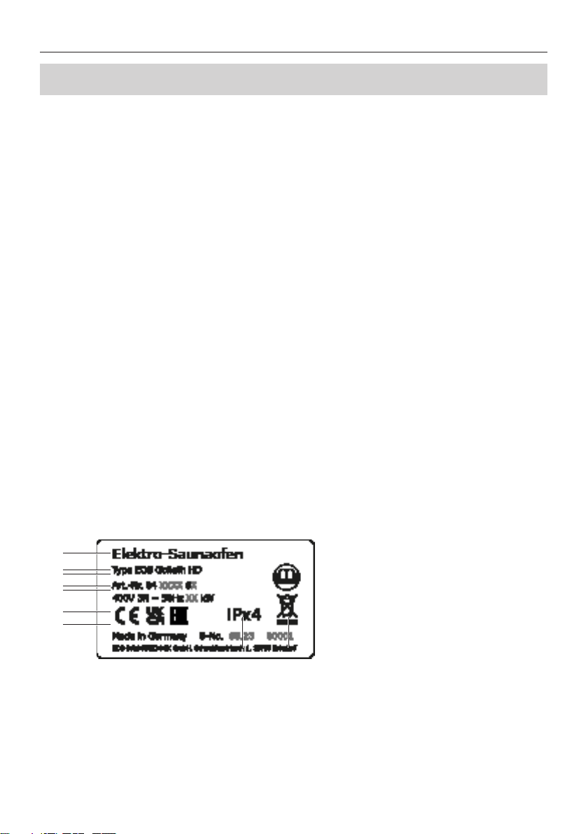
2. Identication.............................................................................................................................................. 10
Manufacturer, Copyright, Identication and Product Information.................................. 10
Intended use ........................................................................................................................................ 11
Foreseeable misuse ........................................................................................................................... 11
General information about sauna use........................................................................................ 12
3. Scope of delivery ...................................................................................................................................... 13
4. Technical Data............................................................................................................................................ 14
5. Electrical Installation ............................................................................................................................... 15
Heating time limitation.................................................................................................................... 15
Connection diagram 18 kW............................................................................................................ 16
Connection diagram 24 – 36 kW................................................................................................... 17
Inner wiring .......................................................................................................................................... 18
Connecting the heater ..................................................................................................................... 19
6. Installation .................................................................................................................................................. 20
Requirements on site........................................................................................................................ 20
Dimensions and safety gaps........................................................................................................... 21
Air inlet and outlet ............................................................................................................................. 22
Requirements for control unit and temperature sensor ...................................................... 23
7. Mounting the optional cover protection rail.................................................................................. 24
8. Commissioning ......................................................................................................................................... 25
Filling the rock store.......................................................................................................................... 25
Switching the sauna heater............................................................................................................ 26
Remote switching .............................................................................................................................. 26
Water splash......................................................................................................................................... 26
9. Maintenance............................................................................................................................................... 28
Cleaning................................................................................................................................................. 28
Sauna stones........................................................................................................................................ 28
10. Recycling ..................................................................................................................................................... 29
11. Service address.......................................................................................................................................... 29
12. General terms and conditions of service ......................................................................................... 30

4
EN General safety instructions
1. General safety instructions
Safety instructions and important operating instructions are classied. Please familiarise yourself
with the following terms and symbols:
Safety levels
CAUTION
Caution
Indicates a hazardous situation which, if not avoided, could result in minor or moderate
injury.
NOTICE
Notice
Indicates a hazardous situation which, if not avoided, will result in damage to the unit.
WARNING
Warning
Indicatesa hazardoussituationwhich,ifnotavoided,couldresultindeathor serious injury.

5
General safety instructions
1.1 Mounting and electrical installation
These installation instructions are intended for qualied personnel familiar with the
laws and regulations applicable to electrical installations at the installation site. Ob-
serve the following general safety instructions during mounting, conguration and
commissioning of the product.
►Risk to life and limb and risk of re
Risk to life and limb from electric shock and re in the event of improper or faulty electrical
connection. This risk remains also after completion of the installation work.
The electrical installation of the heater, relay boxes and other electrical systems
or equipment with a xed mains connection must only be performed by a trained
electrician from an authorised electrical company.
Ensure compliance with the applicable standards and regulations for electrical
installation.
The system must be completely disconnected from the mains supply before com-
mencing installation and repair work.
The housing cover must only be removed by a specialist.
►Fire hazard from overheating
Insucient ventilation can lead to device overheating and re.
Install air inlets and outlets in the cabin.
Observe the cabin manufacturer’s safety and installation instructions.
►Risk of re due to sauna stones
It is possible for hot stones or stone pieces to fall out of the rock store.
The sauna heater may not be placed on a oor made of easily ammable material
(e.g. laminate or synthetic ooring). Ceramic tiles are recommended as a ooring
option.
►Risk of burns from hot glass
Glass surfaces in the cabin become hot while the sauna is in operation.
When installing the cabin, ensure that the touchable glass surfaces on the outside of

6
EN General safety instructions
the cabin may reach a maximum temperature of 76°C. Appropriate protection may
need to be installed if required.
►Risk of burns from hot unit
During operation, the sauna heater may become hot and, if touched, could cause burns.
Maintain a safe distance.
►Sauna cabin and heater
The sauna cabin must be constructed with proper material and built in a professional man-
ner, and the heater must be suited for the cabin.
Sauna heaters and control units may only be used in sauna cabins made of suitable,
low-resin and untreated material (e.g. Nordic spruce).
Multiple heaters may be installed in one sauna if the heater output can properly
supply the cabin volume. In this case, depending on the position, an additional
safety temperature limiter must be installed for each additional heater.
The sauna heater is not designed to be installed or set up in an alcove or under a
bench or sloping roof unless the sauna heater is specically designed and approved
for this type of installation.
Receptacles may not be installed inside the sauna cabin.
Each sauna cabin must have air inlets and outlets.The air inlets and outlets may be
installed below or behind the sauna heater, approx. 5 to 10 cm above the oor. The
minimum dimensions of the air inlets and outlets can be found here:Technical Data,
air inlets and outlets.
The exhaust openings are always installed in the lower part of the wall diagonal
to the sauna heater. The supply and exhaust openings must not be closed. Please
observe the instructions provided by your sauna cabin manufacturer.
Use one of the control units listed below to check and control the sauna heater. This
control unit is xed to a suitable location on the cabin‘s external wall, and the corre-
sponding sensor housings according to the installation instructions that accompany
the control units inside the sauna cabin.
The cabin lighting must be safe for sauna cabin use and installed in such a way that

7
General safety instructions
it can be used safely in a sauna cabin. Ensure that the heater is installed in compli-
ance with the standards and legal norms valid in your country.
The cabin door must open outward and must not have a lock that cannot be opened
in the case of failure.We recommend magnetic or spring locks.
All electrical installations and equipment in a sauna must comply with the IEC
60364-7-703 (DINVDE 0100-703) norm.
1.2 Operator instruction
The operator of the sauna cabin must be instructed in the general safety instructions during
commissioning. The operator must be given a copy of the operating instructions.
►Risk of electric shock
A risk to life and limb from electric shock and re arises in the event of improper repair work.
This risk remains also after work is completed.
The housing cover must only be removed by a specialist.
Repairs and installations must only be performed by a trained specialist.
The system must be disconnected and removed entirely from the mains supply
before commencing repair work.
Use only original spare parts from the manufacturer.
►Fire hazard
Objects placed on the heater can easily be ignited and cause res.
Do not place objects on the heater.
Fill the stone grate as directed.
Inspect the sauna cabin prior to each commissioning.
If you switch on the heater using pre-set timers or a remote control, attach a protec-
tive cover to the heater or install a suitable safety system.
►Health risks
Spending time in a sauna cabin can lead to serious health risks or even death for persons

8
EN General safety instructions
with health impairments.
Persons with health impairments who spend time in a sauna must consult a doctor
before entering a sauna cabin.
►Equipment damage due to overuse
If the cabin is used commercially, the heating time must be set so that the heater switches
o automatically after a specic period of time.
If the heating does not switch o automatically after a dened heating period, cabin
use must be supervised at all times.
Inspect the cabin before each use.
►Damage to health
Excessive time spent in a heated sauna cabin can lead to overheating of the body (hyperther-
mia), which may cause serious health problems and even death. Hyperthermia occurs when
the core temperature of the body exceeds the norm by a few degrees.
Symptoms of hyperthermia include fever, dizziness, lethargy, sleepiness, and fainting. Side
eects of hyperthermia include perception disorders, inability to recognize the need to leave
the room, inability to identify imminent danger, harm to the foetus in the case of pregnant
women, inability to physically leave the room and unconsciousness.
Alcohol, drugs, and medications increase the risk of hyperthermia.
Do not exceed the maximum recommended time in the sauna.
Leave the sauna cabin if your body responds abnormally to the heat or if you do not
feel well.
Avoid alcohol, drugs, and medications when you are using the sauna.
►Operating the unit
This unit should not be used by children or persons with reduced mental capacity or limited
physical or sensory abilities. Children must not play with the unit.
Cleaning and user maintenance must not be performed by children.
Children must be supervised to ensure they do not play with the unit.

9
General safety instructions
1.3 Standards and regulations
For an overview of the standards that were observed during design and construction of the sauna
heaters, please refer to the individual product’s technical data sheet that can be downloaded from
www.eos-sauna.com.

10
EN Identication
2.1 Manufacturer
EOS Saunatechnik GmbH
Schneiderstriesch 1
35759 Driedorf, Germany
Tel.: +49 2775 82-0
Fax: +49 2775 82-431
2.2 Copyright
Copyright for these installation instructions remains with EOS Saunatechnik GmbH.
Copyright as per DIN ISO 16016:
The copying and distribution of this document, as well as the use and communication of its con-
tents without express authorisation, are not permitted. Compensation will be claimed in the event
of infringements. All rights reserved with regard to patent claims or submission of design or utility
patent.
2.3 Product identification
Model name:
EOS Goliath HD
2.4 Product information
►Nameplate
The nameplate is attached on the rear side of the heater (terminal box).
AName
BModel
CItem number
DElectrical connection
EApprovals
FCountry of origin
GManufacturer
HManufacturing date
ISerial number
A
B
C
D
E
F
G
H I
2. Identication

11
Identication
2.5 Intended use
This heater is intended solely for the purpose of heating sauna cabins, together with a suitable
control unit and two relay boxes. EOS Goliath HD is a free-standing heater that is suitable for com-
mercially used cabins.
The heater is not suitable for outdoor use.
It must be operated only in sauna cabins and may not be exposed to environmental conditions
such as extreme humidity and moisture or the possible formation of condensation or corrosive
substances in the ambient air, as well as other weather conditions.
Any use beyond this is considered improper use. Proper use also includes compliance with operat-
ing, maintenance and servicing requirements. The manufacturer is not responsible for unauthor-
ised modications and damages resulting from these modications; the person modifying the
equipment alone shall bear the associated risk.
2.6 Foreseeable misuse
The following are considered instances of foreseeable misuse:
The unit is operated without knowledge of or compliance with the safety instructions.
Operating, service and maintenance requirements are not observed.
The unit is operated by children or persons with reduced mental capacity or by persons
who have not been thoroughly instructed in its use.
The unit is operated without sauna stones or with a rock store that is not lled as directed.
The heater power does not match the sauna volume.
The unit is operated with insucient air supply or exhaust air.

12
EN Identication
2.7 General instructions
Please note that an optimal sauna climate can be achieved only if the cabin with its air
inlets and outlets, the sauna heater, and the control unit are synchronized.
Observe the specications and information provided by your sauna retailer.
Please note that the highest temperatures in the cabin are always above the sauna heater
and that is where the temperature sensor and safety temperature limiter should be
mounted according to the installation instructions for the control units.
The sauna heaters heat the sauna cabin with heated convection air. Fresh air is drawn
in through the air inlet. It is warmed and rises (convection) and is then circulated in the
cabin. Some of the used air is pushed out of the cabin through the cabin’s air outlet. This
creates a typical sauna climate in your sauna.
Note that there is a drop in temperature from the ceiling to the oor of the sauna cabin.
Temperatures are measured and regulated based on the ceiling values. Thermometers
placed below the ceiling will therefore display lower temperatures. When the max.
temperature is set for the area around the upper sauna bench, the bathing temperature is
typically between 80°C and 90°C.
The rst time the cabin is heated, you may notice a slight odour resulting from the evap-
oration of consumables used in the manufacturing processes. Air out your cabin once it
has been heated and before using the sauna.

13
Delivery scope
3. Delivery scope
Check the unit upon delivery to ensure that all components were delivered and that it is in proper
working order. Contact your distributor if components are missing or damaged. The unit must not
be operated if components are missing or damaged.
The following parts are included in the scope of delivery:
1 Sauna heater
1 Installation and operation instructions

14
EN Technical Data
4. Technical Data
Heater power as per DIN 18 kW 24 kW 30 kW 36 kW
Electrical connection 400V 3N ~ 50 Hz
For sauna volume 24 - 35 m³ 35 - 45 m³ 45 - 65 m³ 65 - 75 m³
Minimum size of air inlet and outlet 50 x 6 cm 50 x 8 cm 50 x 10 cm
Weight, without stones and packaging approx. 85 kg
Heater dimentions, H x W x D 83 x 96 x 47 cm
Stone volume approx. 75 kg, caliber 100-150 mm (not included)
Power extension (LSG unit) LSG 10 LSG 36
For use with the sauna control units EOS Econ series, Compact series, EmoTec series, EmoStyle series, EmoTouch series
Leakage current Max. 0.75 mA per kW heater output
Intended use / area of application Use in private and commercial sauna cabins
Fuse protection for control unit 3 x 16 A
Fuse protection for LSG unit 3 x 16 A 3 x 25 A 3 x 50 A 3 x 63 A
Connection mains – control unit 5 x 2,5 mm² 3 x 1,5 mm²
Connection mains – LSG unit 5 x 2,5 mm² 5 x 6 mm² 5 x 10 mm² 5 x 16 mm²
Connection control uni – heater 5 x 1,5 mm² —
Connection LSG unit – heater 5 x 1,5 mm² 5 x 4 mm² 2 St.
5 x 4 mm² 2 St.
5 x 6 mm²
Connection control unit – LSG unit 4 x 1,5 mm²
All line cross-section specications are the minimum cross-sections for the copper line.
►Accessories
Mounting brackets for safety guard rail...................................................................Item no. 947125
Safety guard rail (Abachi) with mounting brackets, 3-sided............................Item no. 947126
Aroma tray for essences and herbs, stainless steel..............................................Item no. 948886
Sauna stones, diabase, 100-150 mm, 20 kg............................................................Item no. 947340

15
Electrical installation
5. Electrical installation
This chapter describes how to connect the EOS Goliath HD to a sauna control unit and to a power
extension unit.
Ensure that electrical installation is performed in compliance with the standards and legal norms
valid in your country..
Following norms must be observed by the installation of sauna heating appliances:
IEC 60364-7-703 bzw. DIN VDE 0100 Teil 703
This standard states in its current edition under amendments paragraph 703.412.05 as follows:
“The additional protection must be provided for all current circuits of the sauna by one or more
fault current protection devices (RCDs) with a rated dierential current not exceeding 30 mA, ex-
cept for sauna heaters.”
If a residual current device (RCD) is installed, ensure that there are no other electrical consumers
not belonging to the sauna system which are fused via this RCD.
If the sauna heater has not been used for an extended period of time, the heater may draw mois-
ture from the ambient air, which, in rare cases, could lead to the RCD to be tripped.This is a physical
process and not a fault on the part of the manufacturer.
In this case, the heater must be heated by a technician under supervision which will bypass the
RCD function. Once the moisture has escaped from the heating elements after approx. 10 minutes,
the RCD can be integrated again in the electric circuit.
If the sauna heater will not be used for an extended period of time, we recommend that you switch
on the heater every 6 weeks so that the heating elements do not accumulate moisture. If, during
commissioning, the RCD is triggered, the electrical installation must be checked again.
The electrician is responsible for properly connecting the heaters; thus, the manufacturer does not
assume liability.
5.2 Heating time limitation
5.1 General instructions for electrical installation
►Heating time limitation operation principle
All sauna heaters, except for those installed in public saunas, and which must be operated under
the supervision of sta, must be equipped with a timer that complies with IEC and EN standards,
which limits the operating time for safety reasons. This timer is typically already integrated in all
EOS sauna control units.
The operation time of a public sauna must be limited so that the heating elements are
without power for a minimum of 6 consecutive hours within a 24 hours before an automat-
ic restart can be made.
Units used in private saunas must be limited to an operating time of 6 hours, and an auto-
matic restart is not permitted.

16
EN Electrical installation
LSG 10
V
N S1
L1 L2 L3 N N W V U
3x16A
Saunaofen
Sauna heater
N U V W N1U1V1W1
ENTWURF
L1 L2 L3 N W V U N
Saunasteuergerät / Control unit /
Boîtier de commande / Пульт управления
3x16A
S1 N
400 V 3N ~
Netz / Mains / Réseau / Сеть
Sensor/
Limiter
400 V 3N ~
Netz / Mains / Réseau / Сеть
max. 10 kW max. 10 kW
LSG
5 5
5
4
5
4
Saunasteuergerät
Control unit
Boîtier de commande
Пульт управления
Saunaofen
Sauna heater
Poêle de sauna
Печь для сауны
Leistungsschaltgerät
Power extension unit
Extension de puissance
Блок расширения мощности
Netz / Mains / Réseau / Сеть
5.3 Connection for Goliath HD 18 kW*
►Connection overview
►Connection diagram
*) for all EOS control units except Compact D18/H18

17
Electrical installation
3 5
5
4
5
4
Saunasteuergerät
Control unit
Boîtier de commande
Пульт управления
Netz / Mains / Réseau / Сеть
LSG
Leistungsschaltgerät
Power extension unit
Extension de puissance
Блок расширения мощности
Saunaofen
Sauna heater
Poêle de sauna
Печь для сауны
U V W N L1 L2 L3 N
U S1 V N
U V W N
LSG
Contactor box
1 1 1 1
L1 L2 L3 N W V U N
Saunasteuergerät / Control unit /
Boîtier de commande / Пульт управления
1x16A
N U V W N U V W
1 1 1 1
S1 N
400 V 3N ~
Netz / Mains / Réseau / Сеть
Saunaofen / Sauna heater
Poêle de sauna / Печь для сауны
Sensor/
Limiter
3x 63A
230 V N ~
Netz / Mains / Réseau / Сеть
5.4 Connection for Goliath HD 24 - 36 kW
LSG 36
Connection overview
Connection diagram

18
EN Electrical installation
►Goliath HD 18 - 36 kW
5.5 Internal wiring
LSG = power extension unit
SCU = sauna control unit
24 kW = 18x 1,333 kW
30 kW = 18x 1,666 kW
36 kW = 18x 2,000 kW
5 x 6
2
5 x 6
2
N
V1W1U1
N
V2W2U2
zum LSG 36
18 kW 24 kW 30 kW 36 kW
ALSG 10 + SCU LSG 36 LSG 36 LSG 36
B18x 1,0 kW 18x 1,333 kW 18x 1,666 kW 18x 2,0 kW
A
B
A. Connection lines
B. Heating elements
►Goliath HD 18 kW single-circuit
A. Connection (EOS Compact D18 control unit / LSG 18 contactor box)
B. Heating elements (RHK), 18 x 1,000 W
5 x 6
2
N
UVW

19
Electrical installation
5.6 Establishing an electrical connection
The connection eects through the terminals in the terminal box at the rear side of the heater.
Opening the terminal box
1. Unscrew the 4 retaining screws from the terminal box cover.
2. Take o the terminal box cover panel.
Connecting the lines
3. Feed the connecting cables through the openings in the terminal box.
4. Attach wire-end ferrules to the ends of the cables (crimp the wires).
5. Connect the neutral conductor to the supply terminal on the„N“ busbar. Connect the phases
to the supply terminals for the 3 phases. Use a torque of 2.5–3 Nm.
Closing the terminal box
6. Mount the terminal box cover panel back on the terminal box.
7. Screw in the 4 retaining screws and tighten them.

20
EN Installation
6. Installation
This chapter describes how to install the Goliath HD sauna heater. Prior to installing the unit, air
inlets and outlets must be installed in the cabin. It may be necessary to mount additional fans in
the inlets/outlets. All protective lms must be removed.
6.1 Requirements for the sauna cabin
The cabin must be planned and installed according to specications before the heater is installed.
All electrical installations laid inside the cabin must be suitable for a temperature of at least 170°C.
All lines must be routed in such a way that they are well-protected, e.g. in a cable duct.
If single-core lines are used as connecting cables, they must be protected by a exible metal hose
that is connected to the protective conductor.
In general, it should be noted that the sauna heater must not be set on a oor made of highly
ammable material such as laminate, ooring made of plastic material, etc. Ceramic tiles are rec-
ommended as a ooring option. Floor heating in the sauna cabin increases the temperature of the
oor’s surface temperature.
►Installation site
Ceiling height of at least 2,10 m
Distance between heater’s top and sauna ceiling at least 127 cm.
Distance between heater and cabin wall at least 8 cm
Distance between heater and bench at least 8 cm
The installation height of the safety guard must not be higher than the heater’s top.
The required heater’s power depends on the sauna volume. See chapter 4. Technical Data.
HINWEIS
Damage due to incorrect mounting location
The heater is not suitable for outdoor use!
The heater must be operated only inside buildings and may not be exposed to
environmental conditions such as extreme humidity and moisture or the possible
formation of condensation or corrosive substances in the ambient air, as well as
other weather conditions.
The heater is not designed to be installed or set up in an alcove or under a bench or
sloping roof.
Table of contents
Other EOS Heater manuals

EOS
EOS Mythos S35 User guide

EOS
EOS Cubo Planning guide

EOS
EOS 94 3742 Installation guide

EOS
EOS Zeus S User manual

EOS
EOS Stativ Terra Vita II User manual

EOS
EOS Vitae protect Planning guide

EOS
EOS Zeus User guide

EOS
EOS Vitae Protect+ Planning guide

EOS
EOS Mythos S35 User manual

EOS
EOS Bi-O Star Series User manual
Popular Heater manuals by other brands

Berko
Berko HUHAA520 Installation & maintenance instructions

DeLonghi
DeLonghi HOR KH590715 instructions

Desa
Desa RH125TH owner's manual

Temper
Temper KOBTP400BL Installation manual and instructions for use

Airmark
Airmark GFW SERIES Installation & operating instructions

Technotherm
Technotherm TTS 200 Installation and technical manual