Jandy Ray-Vac Installation and user guide

Installation Data
Installation Manual
H0555000B
FOR YOUR SAFETY - This product must be installed and serviced by authorized
personnel qualified in pool/spa installation. Improper installation and/or operation can
create a hazard which can cause serious injury property damage or death. Improper
installation and/or operation will void the warranty.
WARNING

TABLE OF CONTENTS
SECTION 1
Safety Information
1A. Safety Instructions................................... 1
SECTION 2
General Information
2A. Introduction.............................................. 2
SECTION 3
Wall Mounting Location
3A. Pool Cleaner Line.................................... 2
SECTION 4
Head and Hose Installation
4A. Attaching Ray- ac Head to Hose............ 2
4B. Connecting Ray- ac Head to Pool Wall...2
4C. Hose Length Adjustment..........................3
Equipment Information Record
Date of Purchase Purchased From
Ray-Vac Model Number
Serial Number
Installed by Service Number
Notes:
SECTION 5
Speed Adjustment with Booster ump
5A. Speed adjustment.................................... 6
SECTION 6
Speed Adjustment without Booster ump
6A. Speed Adjustment................................... 8
SECTION 7
Troubleshooting
7A. Troubleshooting...................................... 10
SECTION 8
Exploded Views
8A. Hose..................................................... 11
8B. Heads................................................... 12

SECTION 1.
Safety Information
1A. Safety Instructions
READ AND FOLLOW THESE SAFETY INSTRUCTIONS!
LEASE SAVE THESE INSTRUCTIONS
Caution
1. Handrails which extend into the water must be removed or substituted with a figure four
design so as not to obstruct the movement of the cleaner.
2. Ladders present a special situation requiring our special Ladder Guard Kit. f the ladder
guard is not installed on the cleaner head, the unit can become entangled in the ladder.
3. deal pools are those with curved corners with a radius of at least 6" including all steps
and love seat areas. Pools with square corners or corners with less than 90° angles
(especially in step or love seat areas) can cause problems.
4. Never install the pool cleaner in pools which have obstacles such as islands, stools, or
non-removable fountains, as the cleaner can become entangled.
Page 1

SECTION 2.
General Information
2A. Introduction
This manual contains information for the proper
installation and operation of Jandy Ray-Vac Automatic
Pool Cleaners. Procedures in this manual must be
followed exactly. To obtain additional copies of this
manual contact us at 0 - 6-8200, ext. 23 . For
address information see back cover.
The Ray-Vac Pool Cleaner requires either (1) an
operable booster pump installed in the pool circulation
system: or (2) the pool circulation system plumbed per
Jandy installation instructions for non-booster pump
applications. If you are uncertain if the pool meets one
of the above requirements, consult your local pool
professional.
SECTION 3.
Wall ounting Location
3A. ool Cleaner Line
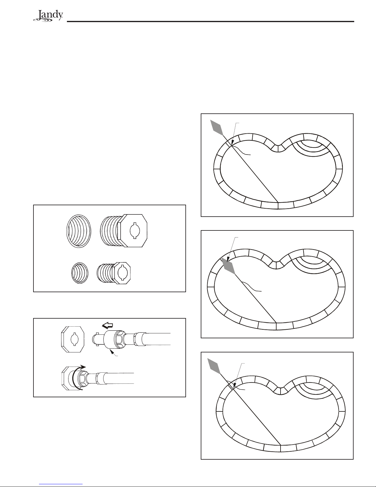
1. The pool cleaner line should be located on the
"clean wall" (no obstacles such as steps, love
seats, ladders, etc.).
2. The location should also be equidistant from the
furthest points of the pool (see Fig. 1).
3. Position the pool cleaner so that it will be 6" to 8"
below the normal water level of the pool.
Page 2
Figure 2. Ray-Vac Hose in Pool
6" to 8"
SECTION 4.
Head and Hose Installation
4A. Attaching Ray-Vac Head to Hose
1. Unpackage and lay out hoses. Locate Ray-Vac
pool cleaner head. Locate package of lettered
reducer washers (Booster Pump Kit).
Note: The washers are for use with booster pump
cleaner only. Do not use for non-booster pump
installation.
2. Insert barbed end of pusher jet into silicon hose
on Ray-Vac head. Be sure silicone hose
completely covers barb and is on straight
(see Fig. 3).
Ray-Vac
Head
Silicon
Hose
Pusher Jet
& Hose
Figure 3. Attaching Pusher Jet Hose to Ray-Vac Head
Push Hose
On To Here
Figure 1. Pool Cleaner Line Location
AB
A and B are qual Lengths
4C. Hose Length Adjustment
1. Grasp the Ray-Vac head and take it to the farthest
point away from the wall fitting in the pool. The
Ray-Vac should be able to extend out of the pool
approximately 2' to 5'. If the Ray-Vac does not
Figure . Ray-Vac Hose too Long
RAY-VAC HOS
L NGTH TOO LONG
Page 3
Farthest Point
Figure 4. Wall Reducers
1½" Wall
Reducer
¾" Wall
Reducer
1½" Pool
Wall Fitting
¾" Pool
Wall Fitting
4B. Connecting Ray-Vac Hose to ool Wall
1. Locate the pool cleaner wall fitting in the pool.
Determine the size of the wall fitting. The most
common size is 1½", but some wall fittings are
¾". If you do not have the ¾" or 1½" wall fitting,
consult your pool professional.
2. Thread the correct wall reducer into the pool
wall fitting. Hand tighten only.
3. To connect the Ray-Vac hose to the pool wall,
insert the quick disconnect fitting (end of Ray-
Vac hose) into the wall reducer. Line up tabs on
fitting with slots in wall reducer. Push in firmly
until the fitting is flush in wall reducer, then turn
clockwise until locked.
4. To disconnect the Ray-Vac, push in firmly on
fitting and turn counterclockwise and pull out.
Figure 5. Quick Disconnect Fitting
Quick Disconnect Fitting
Wall
Reducer
Wall
Reducer
Line
Whip
Figure 7. Ray-Vac Hose too Short
RAY-VAC HOS
L NGTH TOO SHORT
Farthest Point
Line
Whip
Figure 6. Correct Ray-Vac Hose Length
CORR CT L NGTH
FOR RAY-VAC HOS
Farthest Point
Line
Whip
reach out of the pool, the hoses are too short. If
the Ray-Vac extends beyond 5' out of the pool, the
hoses are too long (see Figs. 6-8).
Note: Before operating the cleaner for the first time or
if the cleaner has been coiled for an extended
period, it is advisable to stretch the entire
cleaner out in the sun for a day to soften the
hoses and prevent tangling.
2. If your Ray-Vac hoses are the correct length,
proceed to Section 5, "Speed Adjustment Booster
Pump Installation" or Section 6, "Speed
Adjustment Non-Booster Pump Installation."
3. If your Ray-Vac hoses are NOT the correct
length, use one of the following steps to correct
the hose length:
a. If the hose length is too long, remove 3' hose
sections as required to shorten the hose.
Follow hose section numbering for order of
removal when you must remove more than
one section.
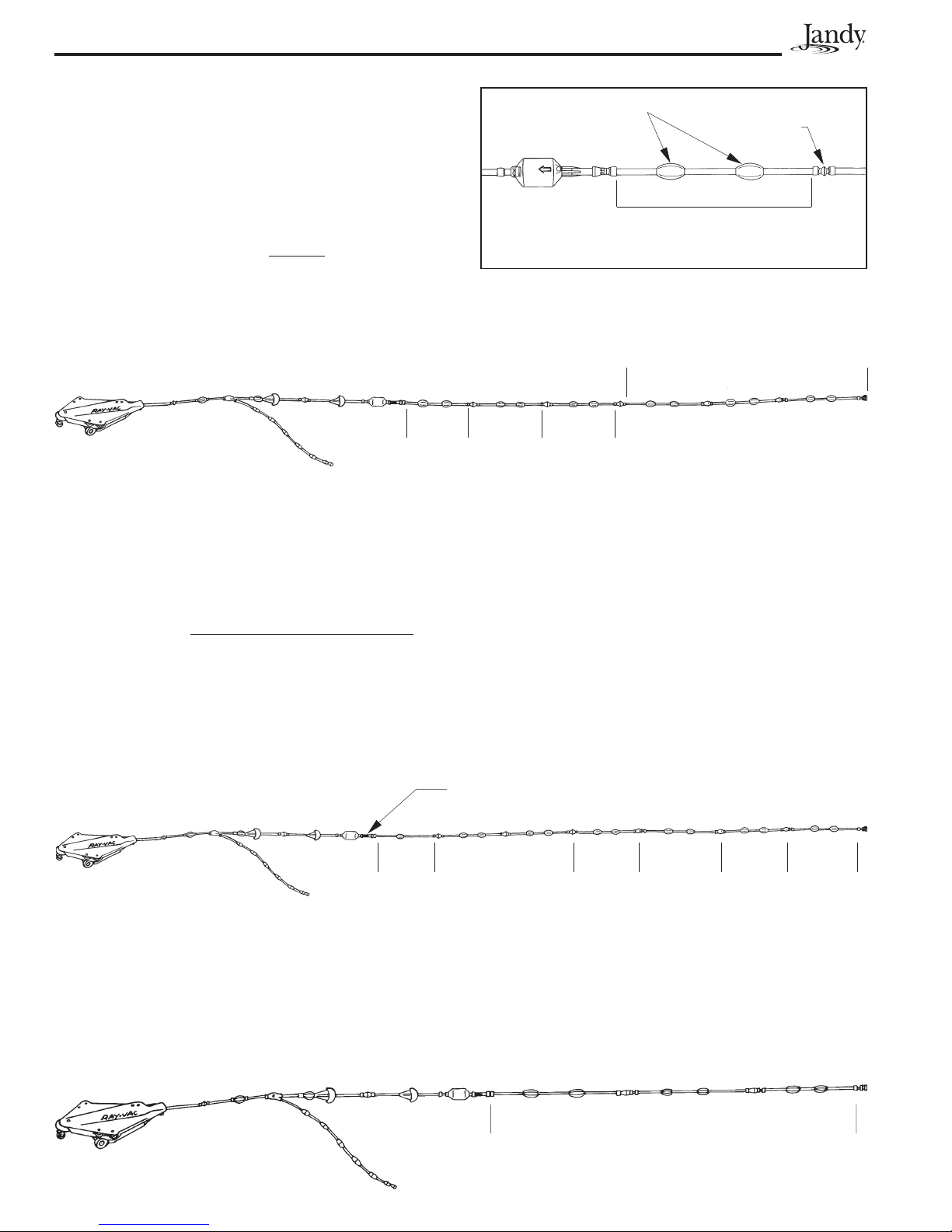
b. If the pool size is 20' x 40' or greater and the
cleaner hose requires seven 5/8" hose
sections or more to size the cleaner correctly
to the pool, you must set the floatation as
follows: Starting at the finger screen case
there must be two (2) floats on all sections,
except the section nearest the hydro-timer.
The hose section nearest the hydro-timer
should have one (1) float in the center of the
hose. If your Ray-Vac requires eight (8)
sections or more, a booster pump may be
needed. Consult your pool professional.
c. If the pool size is 15' x 30' or less, all sections
between the hydro-timer and the wall mount
should now have two (2) floats.
Figure 9. Ray-Vac Hose Section
Hydro-Timer,
Do Not Remove Section of Hose
Floats
Remove one or more of these sections to shorten length.
1st
Section
to be
removed
2nd
Section
to be
removed
3rd
Section
to be
removed
Do Not Remove These
Three (3) Sections
Coupler
Finger Case
Screen
Last
Section
1 Float
4th
Section
2 Floats
3rd
Section
2 Floats
2nd
Section
2 Floats
1st
Section
2 Floats
ach additional section requires 2 floats.
Three (3) 5/8" Hose Sections w/ 2 Floats per section
Page 4

4. To disconnect hose sections
a. Remove the "C" clip from the coupler.
b. Slide mender sleeve off hose.
c. Pull hose off the coupler.
d. Remove mender ferrule from hose (5/8" hose
only).
Do not lose mender ferrule.
Figure 10. Disconnect Hose Section
"C" Clip
Coupler
Remove "C" Clip
Mender Sleeve
Slide Mender Sleeve off Hose
Figure 11. Disconnect Hose Section
Hose
Section
Pull Hose from Coupler
Coupler
Remove Mender
Ferrule from Hose
Mender
Ferrule
5. To reconnect hose sections:
a. Place mender sleeve loosely over hose
coupler small end first.
b. Place mender ferrule over hose section.
c. Push hose section and ferrule onto coupler.
d. You must pull the mender sleeve, mender
ferrule and hose hard enough to expose the
valley behind the barb on the coupler. If the
"C" clip is not in the valley the mender
sleeve can slide off and the hose will come
apart.
e. Snap "C" clip into valley in the coupler. The
clip must "snap" into the valley behind the
mender sleeve.
Figure 12. Reconnecting Hose Section
Slide Mender Ferrule onto Hose
Slide Mender Sleeve onto Coupler
Slide Hose onto Coupler
Page 5
Mender
Ferrule
Figure 13. Reconnecting Hose Sections
Slide Mender Sleeve onto Hose
Push "C" Clip into
Valley on Coupler
Valley
SECTION 5.
Speed Adjustment with Booster
Pump
This section assumes that a booster pump is
properly plumbed and operating in the pool circulation
system. If not, you must install a booster pump before
proceeding (see instruction package with the booster
pump for installation). If you are uncertain whether the
pool has a booster pump, check with your local pool
professional.
5A. Speed Adjustment
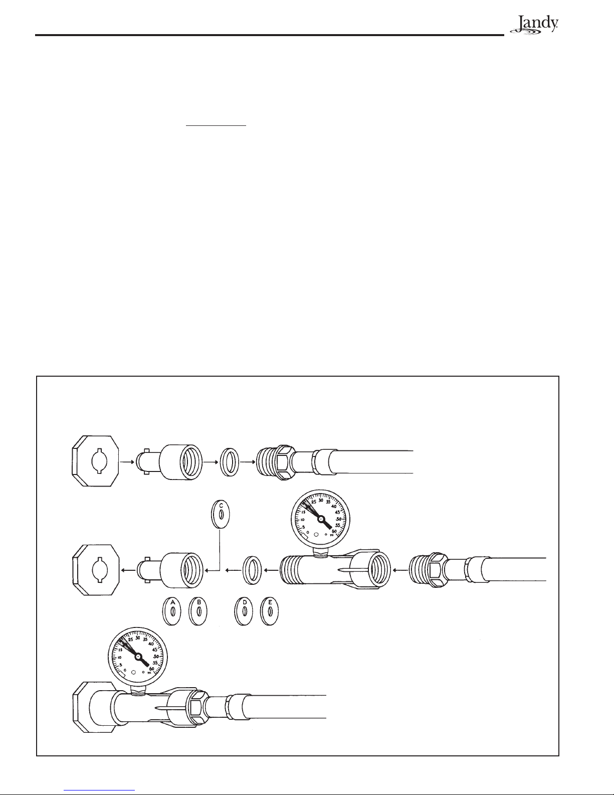
1. From the kit, take the pressure gauge and thread
it into the test gauge case.
2. Locate where the Ray-Vac hose is connected to
the pool wall. Turn the quick disconnect fitting
and remove the hose from the pool wall fitting.
3. Unscrew the quick disconnect fitting from the end
of the cleaner hose. Remove the hose washer
from the quick disconnect fitting (see Fig. 14).
4. From the selection of five (5) speed adjustment
washers, select "C" and place it into the quick
disconnect fitting (see Fig. 4).
5. Insert the hose washer into the quick disconnect
fitting. The hose washer will hold the speed
adjustment washer in place.
6. Thread the quick disconnect fitting onto the end
of the filter screen case that has external threads
and thread this assembly onto the end of the
cleaner hose.
. Insert quick disconnect fitting back into pool wall
fitting (see Fig. 5).
8. At the equipment pad turn on the filter pump. Wait
until the system is fully primed (pressure shows
on filter tank gauge).
Page 6
0-60 Pressure Gauge
Test Gauge Case
Speed Adjustment
Disk C
Speed Adjustment
Disks (A , B, D, & E)
Wall Fitting Quick Disconnect
Fitting Hose Washer
End of Ray-Vac Hose
Figure 14. Speed Adjustment
Page 7
9. Turn on booster pump.
10. At pool side, read the pressure gauge installed on
cleaner hose. Pressure should be set (see Table
1) for the length of hose in your pool.
11. If the pressure is too low, replace the speed
adjustment washer with "D" or "E" speed adjust-
ment washer (follow steps 1-10). Each letter up
will increase pressure approximately 2 psi.
12 If the pressure is too high, replace the speed
adjustment washer with "A" or "B" speed adjust-
ment washer (follow steps 1-10). Each letter
down will decrease pressure approximately 2 psi.
13. When the Ray-Vac speed is properly adjusted,
turn off all pumps.
14. Remove the pressure gauge and filter screen
case from the pool wall. Unthread the quick
disconnect fitting from the filter screen case.
Remove the washer and speed adjustment disk.
Place the washer back into the quick
disconnect fitting.
15. Unthread the filter screen case from the end of
the hose. Thread the quick disconnect fitting back
onto the hose end (see Fig. 6).
16. Push the quick disconnect fitting into the pool wall
fitting.
1 . Shake the water out of the pressure gauge and
store the unit for future adjustment (if necessary).
18. Turn on the filter pump to prime the system.
When there is pressure in the system, turn on the
booster pump.
19. Check operation of the cleaner.
Length of hose
between wall
fitting and nose
of Ray-Vac
Pressure
Setting on
Gauge
21' 5"
24' 5"
2 ' 5"
30' 5"
33' 5"
18 psi
19 psi
20 psi
21 psi
22 psi
Table 1. Ray-Vac Pressure Settings
NOTE: Information in this table is a "guideline" only.

Page 8
SECTION 6.
Speed Adjustment Non-Booster
Pump
This section assumes that a Jandy Energy Filter
and Valve or a Jandy Energy Valve is properly installed
in the pool circulation system. If not, you must use a
booster pump or the equivalent. If you are uncertain
check with your local pool professional.
6A. Speed Adjustment
1. At the equipment pad, turn off the filtration pump.
Follow filter manufacturer's recommended
procedures for cleaning main filter. Before
cleaning main filter, be sure to turn the Jandy 3-
port valve so the line to the Ray-Vac is closed.
Figure 15. Ray-Vac Energy Filter and Jandy Valve
From Pump To Main Filter
To Ray-Vac
Turn handle until
pipe to nergy
Filter is closed
Figure 16. Removing Ray-Vac Energy Filter Bowl
Jandy nergy Filter
Turn Clockwise
to Loosen
Turn handle until
pipe to nergy
Filter is closed
From Pump
To Main Filter
If the Bowl is too
tight, use a
screwdriver to
loosen
2. Check the Jandy Energy Filter bowl. If clogged,
you must clean the filter. Use the following steps:
a. Grasp clear bowl.
b. Remove the clear bowl and filter element. If
the bowl is tight, place a large screwdriver
between two of the tabs at the bottom of the
bowl. Use the shank of the screwdriver as a
lever to loosen the bowl.
c. Rinse off the filter element and replace into
bowl.
d. Tighten clear bowl by spinning the bowl into
the housing until resistance is felt. Then
tighten ¼ turn further. Do not over tighten.
NO E: If your pool filter is a diatomaceous earth
(D.E.) type you must leave the Ray-Vac line closed
during the filter recharging period (adding D.E.).
Table of contents
Other Jandy Swimming Pool Vacuum manuals


