Janome FA4 User manual

SERVICE MANUAL
MODEL: FA4
First Edition: 15 November 2019

TABLE OF CONTENTS
TO CHANGE THE FACE PLATE UNIT .................................................................................................. 1
TO CHANGE THE BELT COVER............................................................................................................2
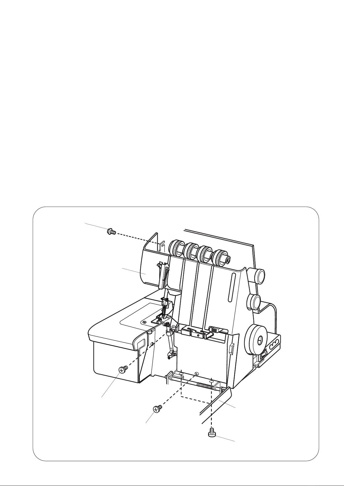
TO CHANGE THE TOP COVER UNIT....................................................................................................3
TO CHANGE THE FRONT COVER UNIT...............................................................................................4
TO CHANGE THE FREE ARM COVER UNIT.........................................................................................5
TO CHANGE THE MACHINE BASE.......................................................................................................6
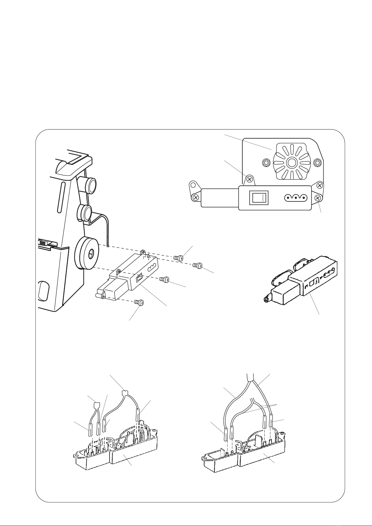
TO CHANGE THE MACHINE SOCKET..................................................................................................7
TO ADJUST THE MOTOR BELT TENSION............................................................................................8
TO ADJUST THE NEEDLE HEIGHT.......................................................................................................9
TO ADJUST THE PRESSER BAR HEIGHT..........................................................................................10
TO ADJUST THE FEED DOG HEIGHT ................................................................................................11
TO ADJUST THE TIMING OF THE NEEDLE AND THE FEED DOG ...................................................12
TO ADJUST THE TIMING OF THE NEEDLE AND THE UPPER KNIFE ..............................................13
TO ADJUST THE CLEARANCE BETWEEN THE NEEDLES AND
THE LOWER LOOPER/NEEDLE GUARDS ................................................................................14 to 16
TO ADJUST THE CLEARANCE BETWEEN THE NEEDLES AND
THE FIXED NEEDLE GUARD ..............................................................................................................17
TO ADJUST THE POSITION OF THE CHAINING FINGER .................................................................18
TO ADJUST THE POSITION OF THE UPPER LOOPER.....................................................................19
TO ADJUST THE TIMING OF THE NEEDLE AND THE LOWER LOOPER .........................................20
TO ADJUST THE TIMING OF THE UPPER AND LOWER LOOPERS.................................................21
TO ADJUST THE CLEARANCE BETWEEN THE LOOPERS ..............................................................22
TO ADJUST THE CLEARANCE BETWEEN THE NEEDLE AND THE UPPER LOOPER ...................23
TO ADJUST THE POSITION OF THE KNlVES ....................................................................................24
TO ADJUST THE POSITION OF THE LOOPER THREAD GUlDE ......................................................25
TO ADJUST THE STITCH LENGTH .....................................................................................................26
TO ADJUST THE THREAD TENSION DIALS.......................................................................................27
PARTS LIST .................................................................................................................................28 to 50

1
TO CHANGE THE FACE PLATE UNIT
To remove:
1. Loosen the setscrew A and remove the face plate unit.
To attach:
2. Fit the U-groove of the face plate between the setscrew A and set plate, put the ribs of face plate into the front
cover unit, back cover unit and tighten the setscrew.
Top cover unit
Front cover unit
Face plate unit
U-groove
Back cover unit
Set plate
Setscrew A

2
TO CHANGE THE BELT COVER
To remove:
1. Loosen setscrew A and remove the setscrew B.
2. Remove the belt cover.
To attach:
3. Put the ribs of belt cover into the front cover unit and back cover unit and tighten setscrews A and B.
Front cover unit
Setscrew A
Belt cover
Back cover unit
Setscrew B

3
TO CHANGE THE TOP COVER UNIT
To remove:
1. Remove two setscrews A and remove the top cover unit.
To attach:
2. Put the ribs in the front cover unit.
3. Tighten two setscrews A.
Setscrew A
Top cover unit
Front cover unit
Rib

4
TO CHANGE THE FRONT COVER UNIT
To remove:
1. Remove the setscrews A and looper cover unit.
2. Remove the top cover unit. (see page 3)
3. Move the upper looper to its lowest point by turning the handwheel in counterclockwise.
4. Loosen the setscrew B and remove the setscrews C and D and remove the front cover unit.
To attach:
5. Attach the front cover unit, and tighten the setscrews B, C and D.
6. Attach the top cover unit.
7. Attach the looper cover unit and tighten the setscrews A.
Setscrew B
Front cover unit
Setscrew C
Setscrew D
Setscrew A
Looper cover unit

5
TO CHANGE THE FREE ARM COVER UNIT
To remove:
1. Remove setscrews A and remove the free arm cover unit.
To attach:
2. Put the ribs of free arm cover into back cover.
3. Tighten the setscrews A.
Setscrew A

6
TO CHANGE THE MACHINE BASE
To remove:
1. Remove setscrews A, B and four hinge screws C and remove four base cushions D and
washers.
2. Remove the machine base unit.
To attach:
3. Attach the machine base and the four base cushions D, washers, and tighten hinge screws C.
4. Tighten setscrews A and B.
Washer
Base cushion D
Washer
Hinge screw C
Setscrew A
Setscrew B

7
TO CHANGE THE MACHINE SOCKET
To remove:
1. Remove the belt cover. (see page 2)
2.Removesetscrews(A,B)andthemachinesocketunitfromthemotorxingplate.
3. Remove two setscrews C and pull out the cord connectors.
To attach:
4. Insert the cord connectors as shown below.
5. Attach the machine socket and tighten two setscrews C.
6.Attachthemachinesocketunitonthemotorxingplateandtightensetscrews(A,B).
7. Attach the belt cover.
Setscrew C
Machine socket
for 220 to 240V
Setscrew A
Setscrew C
Setscrew B
Setscrew A
Motorxingplate
Setscrew B
Machine socket
for 120V
LED lead cord
LED lead cord
Motor lead cord
For 120V
LED lead cord
Motor lead cord
(Blue)
(Red)
(Green)
For 220 to 240
Area
(Blue) (Brown)
(Brown)

8
TO ADJUST THE MOTOR BELT TENSION
Correct Setting:
Tocheckforproperbelttension,pressthebeltinthemiddleofthespanlightlywithyournger(approximately
300 grams-force). The belt should bend 7 to 9 mm.
To adjust:
1. Remove the belt cover (see page 2).
2. Loosen the 2 nuts A, then tighten them a little. Adjust the belt tension, then tighten the nuts securely.
3. Turn the handwheel for a few rotations and re-check the belt tension.
4. Attach the belt cover.
7 to 9 mm
Nut A

9
TO ADJUST THE NEEDLE HEIGHT
Correct Setting:
The distance between the tip of needle on the right and the surface of needle plate should be 11.6
to 12.2 mm when the needle bar is at the highest position.
To adjust:
1. Remove the looper cover unit, top cover unit and front cover unit. (see pages 3 and 4)
2. Turn the handwheel toward you with your hand and set the needle bar at the highest position.
3. Loosen the setscrew A to adjust the height and tighten setscrew A after the adjustment is done.
4. Turn the handwheel toward you one cycle and recheck the needle bar height.
5. Attach the front cover unit, looper cover unit and top cover unit.
O. L G05
Setscrew A
Needle bar
Needle #14
Surface of needle plate
11.6 to 12.2 mm 11.6 to 12.2 mm

10
TO ADJUST THE PRESSER BAR HEIGHT
Correct Setting:
The distance between the surface of needle plate and bottom of presser foot should be 4.7 to 5.3 mm when the
presser bar lifter is raised.
To adjust:
1. Remove the face cover, looper cover unit, top cover unit and front cover unit. (see pages 1, 3 and 4)
2. Raise the presser bar lifter, and loosen the setscrew A.
Then adjust the presser bar height, the side of presser foot should be parallel with the hole of needle plate.
3. Tighten the setscrew A.
4. Attach the front cover unit, looper cover unit and top cover unit.
Presser bar lifter
Setscrew A
Top surface of needle plate
4.7 to 5.3 mm
O.L G05 5 mm
To be parallel
Needle
(Direction of presser foot)

11
TO ADJUST THE FEED DOG HEIGHT
Correct Setting:
When the presser foot is lowered and the feed dogs are at their highest position, the distance
between the surface of needle plate and bottom of presser foot should be 0.75 to 0.95 mm.
To adjust:
1. Remove the free arm cover unit and the back cover unit. (see page 5)
2. Set the stitch length dial at “3” and the differential feed dial at “1.0” .
3. Lower the presser foot and raise the feed dogs to their highest position by turning the handwheel.
4. Loosen the screws A, B and C.
5. Insert the screwdriver in the slit of the eccentric pin.
Adjust the main feed dog by turning the pin then tighten the setscrew A.
(The standard setting of the feed dog height is when the slit on the eccentric pin is horizontal and eccentric
position is at the rear side.)
6. Push the sub feed dog upward and adjust the distance between the surface of needle plate and bottom of
presser foot, then tighten the setscrews B and C.
7. Check the clearance between the feed dog and the slot of the needle plate when the stitch length is set at 5
anddifferentialfeedissetatmaximum.
(If the direction of the eccentric adjustment is incorrect, the needle plate and feed dog may hit or rub each
other.)
8. Attach the free arm cover unit.
Eccentric pin
Setscrew A
Setscrew B
Setscrew C
0.85 mm
O.L G05

12
TO ADJUST THE TIMING OF THE NEEDLE
AND THE FEED DOG
Correct Setting:
When the tip of right needle is at 2 to 4 mm above the needle plate in its downward motion and presser foot is
lowered, the top of the feed dog teeth should be level with the top surface of needle plate at their rearmost
position.
Before adjustment, check if the needle bar height and the feed dog height are correct.
To adjust:
1. Remove the free arm cover unit.
2. Set the stitch length dial at “ 3 “ and the differential feed dial at “ 1.0 “.
3. Raise the presser foot and move the tip of right needle to 3 mm above the needle plate in its downward
motion by turning the handwheel.
4. Lower the presser foot, and loosen two setscrews A for feed cam.
# Turn the feed cam in the direction B if the feed dog is lower than the surface of the needle plate.
# Turn the feed cam in the direction C if the feed dog is higher than the surface of the needle plate.
5. Tighten two setscrews A.
6. Attach the free arm cover unit.
B
C
O.L G05
2 mm
2 to 4 mm
Setscrew A
Top of the feed dog teeth
Top surface of the needle plate
(Downward motion of
the feed dog)
Feed cam

13
TO ADJUST THE TIMING OF THE NEEDLE
AND THE UPPER KNIFE
Correct Setting:
The upper knife timing is the same as that of the needle bar. In fact, when the needle bar is at
highest position, the upper knife should be also at its highest position.
To adjust:
1. Remove the feed arm cover unit.
2. Loosen two setscrews A and adjust the needle and upper knife timing.
3. * Turn the upper knife drive cam to the direction B when the upper knife timing is being delayed.
* Turn the upper knife drive cam to the direction C when the upper knife timing is too soon.
4.TightenthetwosetscrewsArmly.
* The cIearance between the upper knife drive cam and upper knife connecting rod shouId be 1 mm.
5. Turn the handwheel toward you one cycle, and recheck the needle and the upper knife timing.
6. Attach the free arm cover unit.
C
B
When the needle bar
goes up, the upper
knife goes up.
When the needle bar
goes down, the upper
knife also goes down.
Setscrew A

14
TO ADJUST THE CLEARANCE BETWEEN THE NEEDLES
AND THE LOWER LOOPER/NEEDLE GUARDS (1 OF 3)
Correct Setting:
Both right and left needles should have an equal clearance from the front edge of the needle hoIes
on the needle plate.
The standard clearance between the Ieft and right needle and the lower looper is 0 mm to 0.05 mm. (see page
15)
The standard clearance between the needles and the rear needle guard is 0 mm to 0.2 mm. (see page 16)
The above standard clearance allows the needle to slightly touch the front needle guard.
To adjust:
1. Remove the looper cover unit, top cover unit, front cover unit, presser foot, needle plate and needles.
2. Before loosening setscrew C, attach the needle gauge #787-G02 to prevent change of needle
bar height during the adjustment.
Attach two #11 needles on the needle clamp and loosen the setscrew C. Adjust the two needIes,
to make the clearance between both needles and the front edge of the needle hole of the
needle plate equal by turning the needle bar in the D or E direction while pushing up the needle
bar to prevent change of needle bar height.
Retighten the setscrew C and remove the needle gauge.
Needle clamp
Setscrew C Needle bar lower
bushing
No clearance
Needle gauge
(787-G02)
(D)
(E)
Lower looper
Needle
Needle(L)
Needle(R)
Equal
clearance
Needle
plate

15
TO ADJUST THE CLEARANCE BETWEEN THE NEEDLES
AND THE LOWER LOOPER/NEEDLE GUARDS (2 OF 3)
1. Remove the left needle only.
2. Turn the handweel toward you to bring the tip of the lower looper from the left hand to the rear side of
the right needle.
3.LoosenthehexagonalsocketscrewsAonthefrontneedleguardandopenaspacebetweenthefrontneedle
guard and the needle.
4.Next,loosenthehexagonalboltBandslidethelowerlooperunittothefrontortothebacktoadjustthe
clearance between the right needle and the lower looper. The clearance should be 0 mm to 0.05 mm.
RetightenthehexagonalboltB.
Rear needle guard
Lower looper
Front needle guard
Needle #11
0 to 0.05 mm
Lower looper
Front needle
guard
HexagonalsocketscrewA
Rear needle guard
HexagonalboltB
Lower looper base

16
Needle #14
0 to 0.2 mm
Lower looper
Front needle
guard
Hexagonalsocket
screw A
Rear needle guard
Front needle
guard
0 to 0.05 mm
(Rear needle guard is not touching the needle.)
TO ADJUST THE CLEARANCE BETWEEN THE NEEDLES
AND THE LOWER LOOPER/NEEDLE GUARDS(3 OF 3)
1. Change the right needle from #11 to #14.
2. Push the right needle by the front needle guard to adjust the cIearance between the needle and the lower
looper. The cIearance should be 0 mm to 0.05 mm.
3. Attach #14 needle on the left needle position and turn the handwheel toward you to check the clearance
between the left needle and looper.
Make sure the front needle guard is touching the needle slightly and the rear needle guard is not touching the
needle.
4. Check the timing between the needle and the lower looper.
5. Recheck the needle bar height and the clearance between the needle and the lower looper.
Rear needle guard

17
TO ADJUST THE CLEARANCE BETWEEN THE NEEDLES
AND THE FIXED NEEDLE GUARD
Correct Setting:
Theclearancebetweenneedlesandthexedneedleguardshouldbe0.1to0.4mm.
To adjust:
1. Remove the free arm cover unit, presser foot and the needle plate and lower the needle to its lowest position.
2.LoosenthesetscrewsAandadjustthepositionofthexedneedleguard.
3. Tighten two setscrews A.
4. Attach the needle plate and set the needle plate setting knob to guide line S.
5.Checkthepositionofthechainingnger.
6. Attach the free arm cover unit and the presser foot.
Needle plate setting knob
should be set at “S”
Chainingnger
To be touched
Fixedneedleguard
Fixedneedleguard
Needle #14
0.1 to 0.4 mm
Tipofxedneedle
guard
Guide line S
Needle plate
setting knob
Setscrews A
Needle plate setting knob should be set at “S”
The clearance between the
needleandxedneedleguard

18
TO ADJUST THE POSITION OF
THE CHAINING FINGER
Correct Setting:
WhensettheneedleplatesettingknobtoguidelineS,chainingngershouldtouchsideofneedleplate,andtip
ofchainingngershouldbesamelevelwiththetipoftheneedleontheneedleplate.
To adjust:
1. Remove the free arm cover unit and the presser foot.
2. Set the needle plate setting knob to guide line S on needle plate.
3.LoosentwosetscrewsAandmovechainingngerunittocorrectposition.
4. Tighten two setscrews A.
5.SettheneedleplatesettingknobtoguidelineSandR,andcheckthepositionofchainingnger.
6. Attach the free arm cover unit and the presser foot.
Chainingnger
To be touched
Fixedneedleguard
Should be same level
Setscrews A
Figure 1
Needle plate setting knob is to be “S”
Figure 2
To be touched
Needle plate
setting knob
Guide line S
Chainingngerunit
Table of contents
Other Janome Sewing Machine manuals

Janome
Janome RX 18S User manual

Janome
Janome Magnolia 7306 User manual

Janome
Janome 5270QDC User manual

Janome
Janome 2049 User manual

Janome
Janome Quilt Maker Pro 20 VERSA ST User manual

Janome
Janome HD2200 User manual

Janome
Janome MyLock 744 User manual

Janome
Janome M100QDC User manual

Janome
Janome 1600P-QC - User manual

Janome
Janome 3622S User manual

Janome
Janome S521 User manual

Janome
Janome Memory Craft 6700P User manual

Janome
Janome NH22 User manual

Janome
Janome MC5200 - User manual

Janome
Janome MC6700P User manual

Janome
Janome Sewing Machine User manual

Janome
Janome DC 3018 User manual

Janome
Janome Sewing Machine User manual

Janome
Janome SW-2018E User manual

Janome
Janome MS3015 User manual