Jansen TBDJ001-0500X Series User manual

Trough-shaped manure removal belts
Part 1: Installation order
Read before installation
Edition
English (translation of original
manual)
Revision
G
Revision date
1-4-2020
No.
DOKJ005600-023-01EN

2
Preface
Use of this manual
The information in this manual is only applicable to the JPE trough-shaped manure removal belts with a
belt width of 500. These are available in the following versions:
-Horizontal manure removal belt
-Horizontal manure removal belt with knee joint
-Manure elevating belt
Option: rotatable manure elevating belt
Option: movable manure elevating belt
The information in this manual applies to all of these versions, unless specifically stated.
The pictures are informative and may vary from reality, depending on the situation. This is especially the
case for the side plank supports and the legs.
Icons in this manual
These icons have been used at several places in this manual. This is their meaning:
General:
NOTE
Idea
Safety:
Service and technical support
If necessary, contact Jansen Poultry Equipment for further information and support.
Telephone: 0031 (0) 342 –427 000
Fax: 0031 (0) 342 –427 001
All rights reserved.
No part of this publication may be reproduced, stored in a database and / or published in any form or by any means,
electronic, mechanical, photocopying, recording or in any other way without the prior written permission of the publisher.
© Jansen Poultry Equipment

3
Table of contents
Preface............................................................................................................................................................2
Use of this manual ...................................................................................................................................................2
Icons in this manual .................................................................................................................................................2
Service and technical support..................................................................................................................................2
1Lists of components and general information ...........................................................................................5
1.1 Lists of components .....................................................................................................................................5
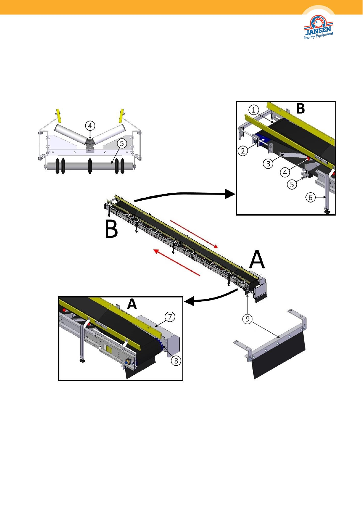
1.1.1 Horizontal manure removal belt ..........................................................................................................5
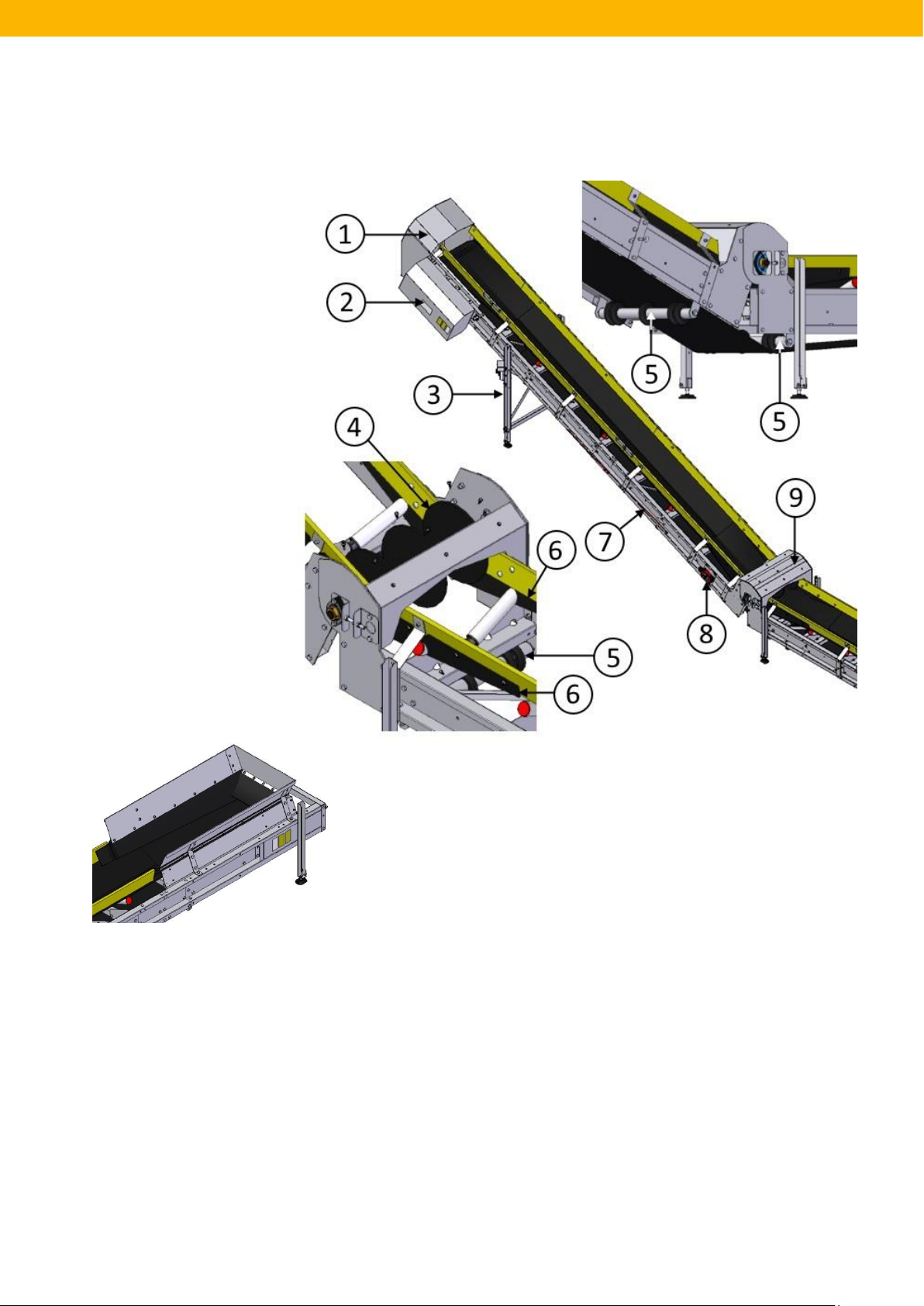
1.1.2 Horizontal manure removal belt with knee joint .................................................................................6
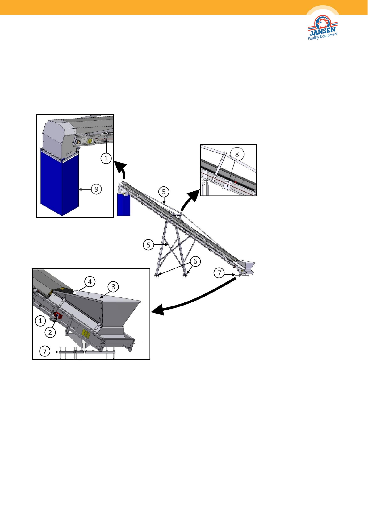
1.1.3 Manure elevating belt..........................................................................................................................7
1.2 List of article numbers..................................................................................................................................8
1.3 Middle sections per length of manure removable belt .............................................................................10
1.4 Installation order........................................................................................................................................11
1.5 Required tools for installation ...................................................................................................................11
2Mounting the frame............................................................................................................................... 12
2.1 Connecting the middle sections.................................................................................................................12
2.2 Connecting the knee joint (belt with knee joint)........................................................................................14
2.2.1 Upwards knee joint ............................................................................................................................14
2.2.2 Downwards knee joint........................................................................................................................15
2.3 Connecting the drive unit...........................................................................................................................16
2.4 Placing the legs of the horizontal parts (horizontal belt and belt with knee joint)....................................17
2.4.1 Fixed leg (horizontal belt and belt with knee joint)............................................................................17
2.4.2 OPTION instead of leg: wheel set (horizontal belt) ............................................................................18
2.5 Coupling the return unit.............................................................................................................................19
2.6 Placing the transport belt...........................................................................................................................20
2.7 Mounting the supporting rollers and tensioning the transport belt .........................................................22
2.8 Mounting the leg under the elevating part (belt with knee joint) .............................................................23
2.8.1 Fixed leg .............................................................................................................................................23
2.8.2 OPTION instead of leg: suspension ....................................................................................................24
2.9 Mounting the return unit support .............................................................................................................24
2.9.1 Mounting the swivel base (rotatable elevating belt) .........................................................................24
2.9.2 Mounting the wheel set (movable elevating belt) .............................................................................25
3Mounting the manure guiding parts .......................................................................................................26
3.1 Placing the funnel.......................................................................................................................................26
3.2 Mounting the side planks...........................................................................................................................27
3.2.1 Side planks in case of a funnel............................................................................................................27
3.2.2 Side planks in case there is no funnel.................................................................................................28
3.2.3 Side planks in case of a knee joint (belt with knee joint)....................................................................29
4Mounting the electrical parts .................................................................................................................31
4.1 Placing the motor.......................................................................................................................................31
4.2 Mounting the isolating switch....................................................................................................................32
4.3 If applicable: mounting the safety set........................................................................................................33
5Options.................................................................................................................................................. 35
5.1 Wall support or suspension (horizontal belt).............................................................................................35
5.1.1 Wall support (horizontal belt) ............................................................................................................35
5.1.2 Suspension in manure storage (elevating belt)..................................................................................36
5.1.3 Additional suspension point from wooden or steel purlins ................................................................36
5.1.4 Suspension in case of intermediate floor (horizontal belt).................................................................37
5.2 Overflow cap (elevating belt and belt with knee joint) .............................................................................37
5.3 Covers and water drainage strip................................................................................................................38

4
5.3.1 Covers.................................................................................................................................................38
5.3.2 Mounting the water drainage strip (elevating belt and belt with knee joint) ...................................39
5.4 Impact plate ...............................................................................................................................................40
5.5 Dump tube .................................................................................................................................................40
5.6 Wall transit (horizontal belt)......................................................................................................................41
6Finishing the elevating belt.....................................................................................................................42
6.1 Mounting the upper arch...........................................................................................................................42
6.2 Placing the leg under the elevating belt ....................................................................................................43
6.2.1 Fixed leg and accompanying buttress set ..........................................................................................43
6.2.2 Rotatable leg (rotatable belt).............................................................................................................46
6.2.3 Movable leg (movable belt) ...............................................................................................................48
7Commissioning of the manure removal belt............................................................................................ 49
Original Dutch manual

5
1Lists of components and general information
1.1 Lists of components
1.1.1 Horizontal manure removal belt
Figure 1.1, Horizontal manure removal belt –operating principle and listed parts are the same for the manure elevating
belt and the horizontal manure removal belt with knee joint
1. Manure belt
2. Return roller (cage roller)
3. V-shaped scraper
4. Troughed idler
5. Supporting roller
6. Leg (standard; suspension from wall with wall
supports is also possible)
7. Cover for drive motor
8. Drive roller (cage roller)
9. Scraper
Moving direction of
upper part of belt
Moving direction of
returning part of belt
Return side
Return side

6
1.1.2 Horizontal manure removal belt with knee joint
Figure 1.2, Horizontal manure
removal belt with knee
joint
1. Cover for drive roller
2. Cover for drive motor
3. Adjustable leg
4. Pressure roller of knee joint
5. Supporting roller
6. HDPE guide plate for
transport belt
7. Emergency pull cord
8. Emergency pull cord switch
9. Knee joint
Figure 1.3, Option: flat collector funnel (on return side)
Drive side

7
1.1.3 Manure elevating belt
The standard manure elevating belt cannot be moved. There are two more options.
Option: rotatable manure elevating belt.
-The leg has wheels.
-A swivel base under the collector funnel.
Option: movable manure elevating belt.
-The leg has wheels.
-A wheel set instead of the swivel base.
Figure 1.4, Manure elevating belt
1. Emergency pull cord
2. Emergency pull cord switch
3. Collector funnel
4. Rubber flaps
5. Bracing strips
6. Leg
7. Swivel base
8. Lifting plates
9. Option: chute for falling manure
Return side
Drive side

8
1.2 List of article numbers
The manure removal belts consist of the following parts. The numbers between brackets in this installation manual
correspond with the list below. The installation drawings of these parts are attached at the end of this manual.
L = length
BW = belt width
.… = may vary
Article numbers
TBDJ001-0500X… Transport belt
EMR…. Drive motor
VUG017X095L3000 Side planks
FRDJ014762-202 Return unit
FRDJ014762-203 Scraper
FRDJ014762-200 Drive right BW500
FRDJ014762-201 Drive unit left BW500
FRDJ014762-204 Collector funnel for elevating belt BW500
FRDJ014762-205 Funnel complete for cross belt BW500
ZMBR011616-272 Maintenance switch
ZMMT014762-801 Swivel base of the conveyor BW500
ZMMT014762-804 Wheel set of elevating belt BW500
ZMMT014762-807 Water drainage strip for cover
ZMMT014762-809 Conveyor segment BW500 L = 1.5 m
ZMMT014762-810 Conveyor segment BW500 L = 2 m
ZMMT014762-811 Conveyor segment BW500 L = 2.5 m
ZMMT014762-812 Conveyor segment BW500 L = 3 m
ZMMT014762-822 Overflow cap of the elevating belt BW500
ZMMT014762-825 Dump tube incl. fastening material for elevating belt BW500
ZMMT014762-831 Small leg elevating belt BW500
ZMMT014762-832 Buttress set for small legs of elevating belt BW500
ZMMT014762-833 Buttress set for upper arch of elevating belt BW500 up to and including a length of 12.8 m
ZMMT014762-834 Lifting plate set for elevating belt
ZMMT014762-835 Leg set for cross belt H = 650 - 800
ZMMT014762-836 Coupling set for side planks
ZMMT014762-837 Coupling set for side profiles of conveyor segments
ZMMT014762-838 Cover manure belt 2 m incl. fastening material BW500
ZMMT014762-839 Rotatable big leg of elevating belt
ZMMT014762-840 Impact plate for cross belt BW500
ZMMT014762-841 Side plank set incl. support for return unit of cross belt
ZMMT014762-842 Cover manure belt 3 m incl. fastening material BW500
ZMMT014762-843 Wall transit cross belt BW500
ZMMT014762-844 Rotatable small leg of elevating belt
ZMMT014762-845 Upwards knee joint complete BW500
ZMMT014762-846 Leg set after knee joint H = 1200 –1700 mm
ZMMT014762-847 Leg set for cross belt H = 900 - 1050
ZMMT014762-848 Extension leg after knee joint
ZMMT014762-849 Wall bracket BW500

9
ZMMT014762-850 Big leg elevating belt BW500
ZMMT014762-851 Buttress set for big leg elevating belt BW500
ZMMT014762-852 Buttress set for top of elevating belt BW500 from 12.8 m up to and including 20.8 m
ZMMT014762-853 Safety kit incl. switch, excl. safety cord
ZMMT014762-855 Downwards knee joint complete BW500
ZMMT014762-856 Roof suspension horizontal belt for longitudinal purlins
ZMMT014762-857 Roof suspension for combination with one fixed point
ZMMT014762-858 Suspension set for elevating part, for two suspension points in the manure storage
ZMMT014762-859 Leg straight height 2250-3550 for elevating belt
ZMMT082060 Suspension set manure belt
ZMMT082061 Extension set for the suspension set manure belt

10
1.3 Middle sections per length of manure removable belt
NOTE! Read on the lay-out drawing what middle sections have to be used per part of the manure removal
belt, what their length is and how many of each are used.
The entire manure removal belt length is determined by:
Drive unit. The installation length of the drive unit is 0.8 m.
Return unit. The installation length of the return unit is 1.5 m.
The amount of meters of middle part (M). This part consists of a number of middle sections, that are
available in four lengths: 1.5 m; 2 m; 2.5 m and 3 m.
Figure 1.6, Meters of middle part in case of a manure elevating belt (measurements in meters)
L = total length
M = meters of middle part
Figure 1.7, Meters of middle part in case of a belt with knee joint (measurements in meters)
M = meters of middle part
Horizontal part
Figure 1.5, Meters of middle part in case of a horizontal manure removal belt (measurements in meters)
L = total length
M = meters of middle part

11
1.4 Installation order
The installation order is equal to the structure of this document. See the table of contents for a list of the correct
installation order.
NOTE! Some sections are only applicable to the horizontal manure removal belt, the horizontal manure
removal belt with knee joint or the elevating belt. In these cases, the belts to which the information in
the section is applicable is added behind brackets and in italics behind the name of the section. When no
specific version is mentioned, the information is applicable to all manure removal belts.
1.5 Required tools for installation
2x socket wrenches and/or ring spanners no. 8, 10, 13, 17, 19
Grinder
Drill
Metal drill 12 mm
Stone drill 12 mm
Level
Hand saw
Phillips head bit
Tape measure

12
2Mounting the frame
IDEA! Do not build the parts on the ground, but build them
at a healthy working height.
NOTE! If you suspend a horizontal manure removal belt
with wall supports or suspension sets, then check the
following. Is there enough space to lift the entire manure
removal belt and fasten it at the correct height? If not, then
the prescribed working order changes.
1. Assemble every middle section at working height,
but do not couple them yet.
2. Install two wall supports or suspension sets.
3. Put the transport belt around a middle section and
place the whole at the correct spot.
4. Repeat this until all middle sections are installed,
with the transport belt already around it.
5. Proceed with section 2.3 and skip what is not
applicable.
2.1 Connecting the middle sections
Connect the middle sections (ZMMT014762-809, -810, -811, -812) by
means of the coupling profiles.
1. Read on the lay-out drawing what middle sections have to be
used per part of the manure removal belt, what their length is
and how many of each are used. See also Figure 2.1.
NOTE! Only in case of a manure removal belt with knee joint:
before installation, always check the manure removal belt
length before and after the knee joint. Keep the available
lengths of middle sections in mind.
NOTE! Start at the drive side with the long middle sections.
Place the shortest middle sections at the return side.
2. Assemble the middle sections until they are as shown in Figure
2.2.
NOTE! Do not mount the side planks, supporting rollers and
coupling sets yet.
NOTE! Mount the troughed idlers perpendicular to the side
profiles. This is important to make the manure belt run
straight.
NOTE! Make sure the front sides of the buttress plates of the
troughed idlers are at the same side (drive side).
Figure 2.1, Lengths of middle sections
Figure 2.2, Building the middle sections
before coupling

13
3. Couple the middle sections by means of the coupling profiles. See Figure 2.3.
a. Place all bolts and nuts loosely.
b. Align the whole.
c. Tighten the upper bolts and nuts in the coupling profile.
d. Tighten the other bolts and nuts.
Figure 2.3, Coupling middle sections
1. Coupling profile
2. Buttress plate of troughed idler
Front sides of the buttress
plates at drive side

14
2.2 Connecting the knee joint (belt with knee joint)
2.2.1 Upwards knee joint
Mount the knee joint (ZMMT014762-845). See Figure 2.4.
1. Remove the troughed idlers before and after the knee joint.
2. Place the knee joint at the desired place, between two middle sections.
NOTE! Make sure the front sides of the buttress plates of the troughed idlers are at the same side (drive
side).
a. Place all bolts and nuts loosely.
b. Align the whole.
c. Tighten the bolts and nuts of the sheet metal parts. (Do not tighten the fixing bolts and adjusting
bolts of the bearings yet.)
3. Mount a side plank support before and after the knee joint.
4. Mount a supporting roller immediately before the knee joint, at the return unit side. See section 2.7.
NOTE! Do not yet install the second supporting roller of the knee joint. Install it after you installed the
transport belt. See section 2.6.
5. Place the cover on the scraper profiles of the knee joint.
NOTE! Before assembly, always check the manure belt length after the knee joint. Keep the available
lengths of middle sections in mind during assembly.
Figure 2.4, Mounting the upwards knee joint
1. Parts that must be removed before and after the
knee joint
2. Middle section
3. Knee joint
4. Scraper profile of the knee joint
5. Side plank supports before and after the knee joint
6. Supporting roller immediately before knee joint
(return unit side)
7. Pressure set
8. Cover
Return unit side
Drive unit side

15
2.2.2 Downwards knee joint
Mount the knee joint (ZMMT014762-855). See Figure 2.5. The assembly order of a downwards knee joint is equal
to the assembly order of an upwards knee joint.
Figure 2.5, Mounting the downwards knee joint
1. Parts that must be removed before and after the
knee joint
2. Middle section
3. Knee joint
4. Scraper profile of the knee joint
5. Side plank supports before and after the knee joint
6. Supporting roller immediately before knee joint
(return unit side)
7. Pressure set
8. Cover
Drive unit side
Return unit side

16
2.3 Connecting the drive unit
The drive unit is supplied assembled and is available in two versions.
Drive unit with the motor at the right side (FRDJ014762-200).
Drive unit with the motor at the left side (FRDJ014762-201).
Connect the drive unit to the middle section. See Figure 2.6.
1. Slide the side profiles of the drive unit and the front middle sections into each other.
2. Mount the drive unit to the front middle section.
a. Place all bolts and nuts loosely.
b. Align the whole.
c. Tighten the upper bolts and nuts.
d. Tighten the other bolts and nuts.
Figure 2.6, Mounting the drive unit (example)
1. Drive unit with motor at the right side

17
2.4 Placing the legs of the horizontal parts (horizontal belt and belt with knee joint)
2.4.1 Fixed leg (horizontal belt and belt with knee joint)
Two leg sets are available for the horizontal parts of a manure removal belt.
Leg set height 650 mm –800 mm (ZMMT014762-835)
Leg set height 900 mm –1050 mm (ZMMT014762-847)
Assemble the leg sets. See Figure 2.7.
NOTE! In each case, always place one leg set before the knee joint and one leg set at the return unit. The
maximal center distance of the leg sets is 3 m!
Figure 2.7, Mounting the legs of horizontal parts
1. Leg set 650 mm –800 mm
2. Leg set 900 mm –1050 mm
Leg set before knee joint
Leg set at return unit

18
2.4.2 OPTION instead of leg: wheel set (horizontal belt)
Mount the wheel set (ZMMT014762-804) of the horizontal parts of the manure removal belt. See Figure 2.8.
Figure 2.8, Wheel set (movable horizontal belt or belt with knee belt)
1. Leg
2. Swivel wheel
3. Cross profile
1. Assemble the wheel set.
2. Place the legs under the manure removal belt, at the distance shown in het installation drawing.
3. Mount the wheel set to the manure removal belt.
NOTE! You can mount the wheel set at two heights.
Mount in existing
hole
Drill hole in side profile

19
2.5 Coupling the return unit
The return unit is supplied assembled. It is the same for all versions of the manure removal belts.
Mount the return unit (FRDJ014762-202). See Figure 2.9.
1. Place the return roller as close as possible to the side of the middle sections.
2. Couple the return unit by means of the coupling profiles.
a. Place all bolts and nuts loosely.
b. Align the whole.
c. Tighten the upper bolts and nuts in the coupling profile.
d. Tighten the other bolts and nuts.
Figure 2.9, Placing the return unit
1. Return unit
2. Coupling profile

20
2.6 Placing the transport belt
Place the transport belt (TBDJ001-0500X…). See Figure 2.10 and Figure 2.11.
1. Place the return roller as close as possible to the side of the middle sections.
2. Disassemble the end cover and supporting roller of the return unit. See Figure 2.10.
NOTE! Leave the supporting roller before the knee joint (4, Figure 2.11) in place. The transport belt
should pass underneath it.
Figure 2.10, Mounting the transport belt on the return roller side
1. End cover
2. Return roller
3. Supporting roller
4. Transport belt
3. Place the transport belt around the return unit.
4. Mount the end cover.
5. Mount the supporting roller. If necessary, see section 2.7.
6. Unroll the transport belt along the frame.
7. Disassemble the scraper of the drive unit.
8. In case of a belt with knee joint:
a. Upwards knee joint: disassemble the cover, scraper profiles and pressure set of the knee joint. If
necessary, see Figure 2.4.
b. Downwards knee joint: disassemble the cover.
9. Place the transport belt around the drive unit and around the knee joint.
NOTE! Place the transport belt in the correct direction of rotation! For the correct direction of rotation,
see the arrow on the transport belt itself. Place the transport belt as it is rolled up: with the thick upper
layer at the outside.
NOTE! To place the transport belt around the knee joint, see Figure 2.11.
For the correct direction of
rotation, see the arrow on the
transport belt itself.
Place the transport belt as it
is rolled up: with the thick upper
layer at the outside.
Table of contents