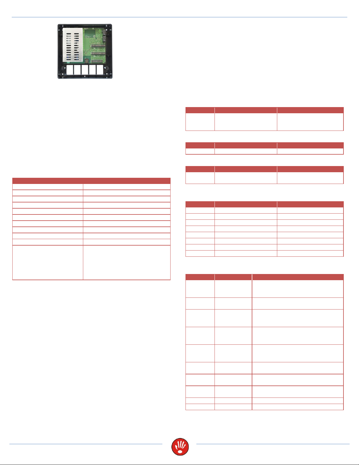
SPIDER W40 –Power supply for 2 controllers with battery support
SPIDER W40 –POWER SUPPLY FOR 2
CONTROLLERS WITH BATTERY SUPPORT
The Spider W40 is a 30 watt power supply for 2 controllers and el.
strikes or el. magnets. It is designed for residential and business
buildings, offices, shops, etc.
It is intended to power controllers for time and attendance, access
controllers and standalone controllers.
The special version of the Spider W40-NET has a built-in TCP/IP
converter, which enables communication between the connected
controllers (and additional controllers in the communication line)
and the access control program via LAN/WAN.
TECHNICAL DATA
Spider W40 and Spider W40-NET
(F100) T1AL, 250 V (5x20mm)
Operation at an altitude of
Class II - This is a class A
product. In a domestic
environment this product may
cause radio interference in which
case the user may be required to
take adequate measures.
Power Supply
The device can operate within a 110-230V AC, 50–60Hz input
range. The output power of the in-built power supply is 30W, 13.8V
fulltime. The power supply has protection against both short
circuits and current overload. In the case of protection activation,
the power will be switched off for 5s. If this is repeated 20 times,
the power supply will switch off until electrical resetting takes place
(unplugging from mains voltage). This protection is activated if
external consumption exceeds 2A.
An appropriate disconnect device should be provided external to
the equipment. A multi-strand/stranded flexible wires connected to
the unit mains input require ferrules.
2.3Ah battery support is included with a charging limit of 13.8 V DC
and shut down at 10.5V. The charging time of an empty battery is
approximately 4 hours. The charging voltage and current are 13.8
V DC and max. 0.625 A. 2.3Ah battery can be installed in the box.
Larger external 12V batteries, such as 7Ah, may also be connected
but recharging times will be longer. When operating from battery,
the output voltage will drop from 13.8V to 10.5V according to
consumption at which point Spider W40 will turn off. Risk of
explosion if battery is replaced by an incorrect type. Dispose of
used batteries according to the manufacturer's instructions.
Voltage drops
When you connect devices to the power supply, use a cable of at
least 0.2mm2diameter. Take into consideration the fact that this
cable has a resistance of approximately 9ohm per 100m. You
should have a minimum of 10V for power supply at device point
(for our controllers). For total case scenario, consider also the
supply voltage drop when operating on a battery.
CONNECTOR DESCRIPTION
Connectors are marked on the circuit board with AC, LAN, POE,
PWR, TMP, DEV1 and DEV2.
CONNECTOR AC –power supply
Power supply
110 –230 V AC
50–60 Hz
CONNECTOR LAN –Ethernet connection
CONNECTOR POE –Ethernet connection + Power supply
Ethernet + Power supply
12 V DC
CONNECTOR PWR –backup battery connection, 12 V DC
output, RS485 communication line (CA, CB)
CONNECTOR DEV1 –connection for controller and el. strike
or other controlled device
Max. 0.3 A. Connect 12V DC to
controller, el. strike, other device
(siren...).
Ground. Connect ground to
controller.
Input for el. strike (also controls 1.
relay). Connect ground to el. strike
and O0 from controller.
Input for alarm. Connect ground
from other device (siren...) and O1
from controller (with alarm output).
Input for door status switch.
Connect magnet for door status
and I0 from controller.
Input for push button. Connect
push button and I1 from controller.
Connect RS485 communication
from controller.
Connect RS485 communication
from controller.