JAR Systems MD-51 SP Series User manual

Ultra-Light Intelligent Service Plus Carts
MD-51XX-SP
Assembly and Configuration Manual
Version D
For a copy of the most up-to-date manual, please contact a
JAR Systems representative or visit:
www.JAR-Systems.com/Support
MD-5150-SP MD-5135-SP

x1
(E5) x4
x1
x1
(A1) x24
x1
(F6)
x1
x1
(B2) x16
x42 or x32
x1
(G7, H8)
x2
x2 x4
1: Attach both side panels to the bottom of the cart.
Position the studs in the side panel into the tabs in
the base and hand tighten 2 nuts (C3) on each side
with the 8mm wrench (F6). Do not use a power tool
to tighten nuts on any step. Use 3 screws and 3
washers (A1) in each corner.
2: Install the tray lid for the bottom shelf using one screw
and one washer (A1) on each side.
3: Install the upper tray. Position over the studs in the
side panels and hand tighten 4 nuts (C3) with the 8mm
box wrench (F6).
Components
Cart Assembly Instructions
4: Install the tray lid for the top shelf using one screw
and one washer (A1) on each side.
5: Align the top panel of the cart with the side panels
and position it in place. Do not secure the top during
this step. The top will be secured in step 19.
x1
x2
(C3) x12 (D4) x12
(I9) Hasp Kit
(MD-5150 only)
Misc.
Extra

6: Attach the gray rubber bumpers to each corner of the
cart’s top using 4 screws (B2) on each. The bumpers
have a top and bottom side to them. The side with
the mold marks should be facing down. To allow for
the cart to be squared in a later step, do not fully
tighten the screws during this step.
7: Attach the rear center support to the top and bottom
panels of the cart using 2 screws with 2 washers (A1)
on each end. To allow for the cart to be squared in a
later step, do not fully tighten the screws during
this step.
8: OPTIONAL- If installing the charging cables at the
same time as the cart assembly, installing after step
7 provides the most unimpeded workflow. See page
6 for cable management instructions. Don’t worry,
you can still easily install the charging cables after the
cart is fully assembled if needed.
9: Attach the door to the hinge on the right side panel
with 4 screws and 4 washers (E5). Insert the Torx key
(F6) through one of the screw holes on the hinge and
door to help hold it in place. Remove the key once the
first 3 screws are inserted. Insert the 4th screw while
holding the door. Check that the door is square and
opens/closes without striking the frame.
10: Attach the brackets for wrapping the power cable
to the cart’s left side panel using 1 screw and washer
(A1) on each.
11: Attach the mounting plate for the Intelligent Charging
System to the top of the cart using 2 screws with
washers (D4).

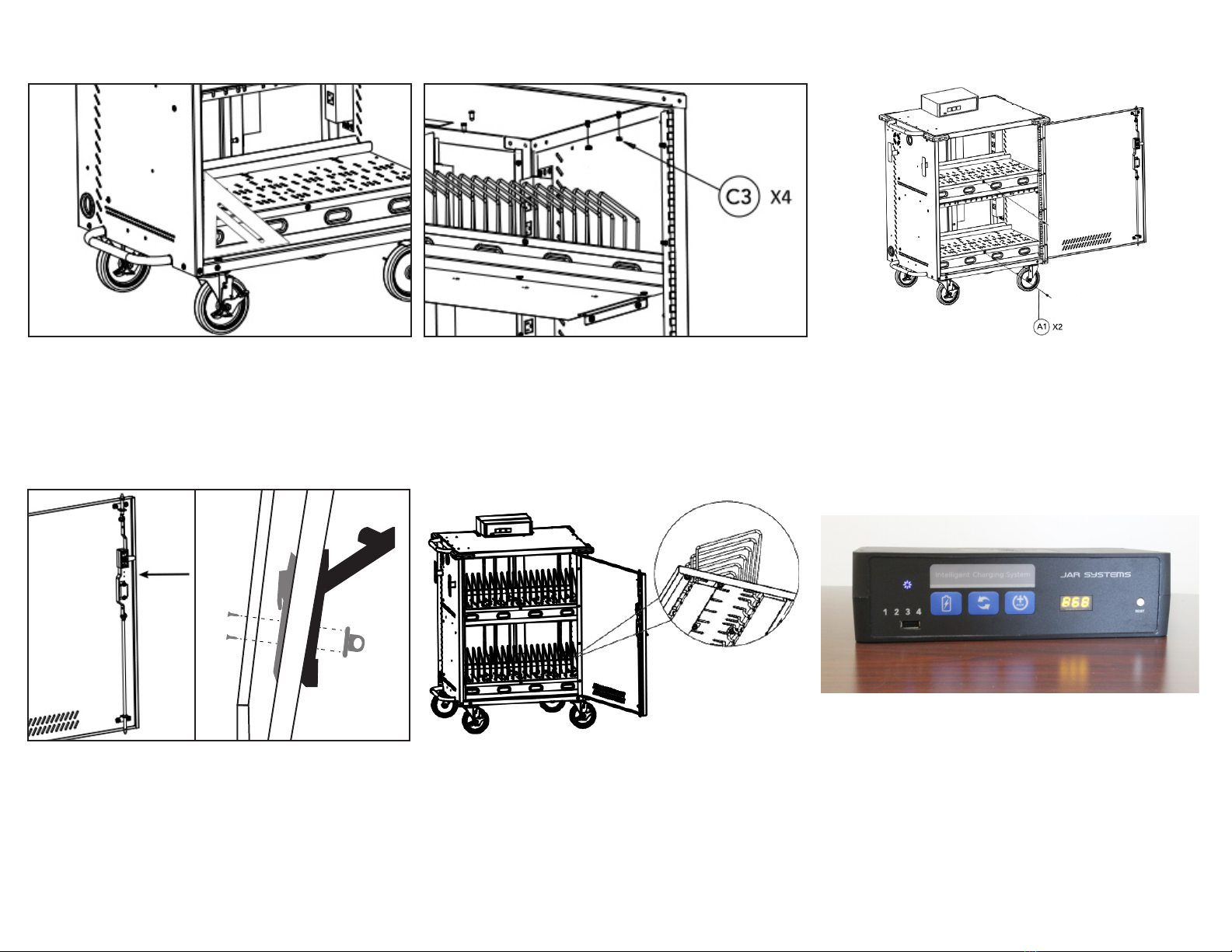
12: Align the openings on the bottom of the Intelligent
Charging System with the clips on the mounting
bracket and apply pressure to clip it into place.
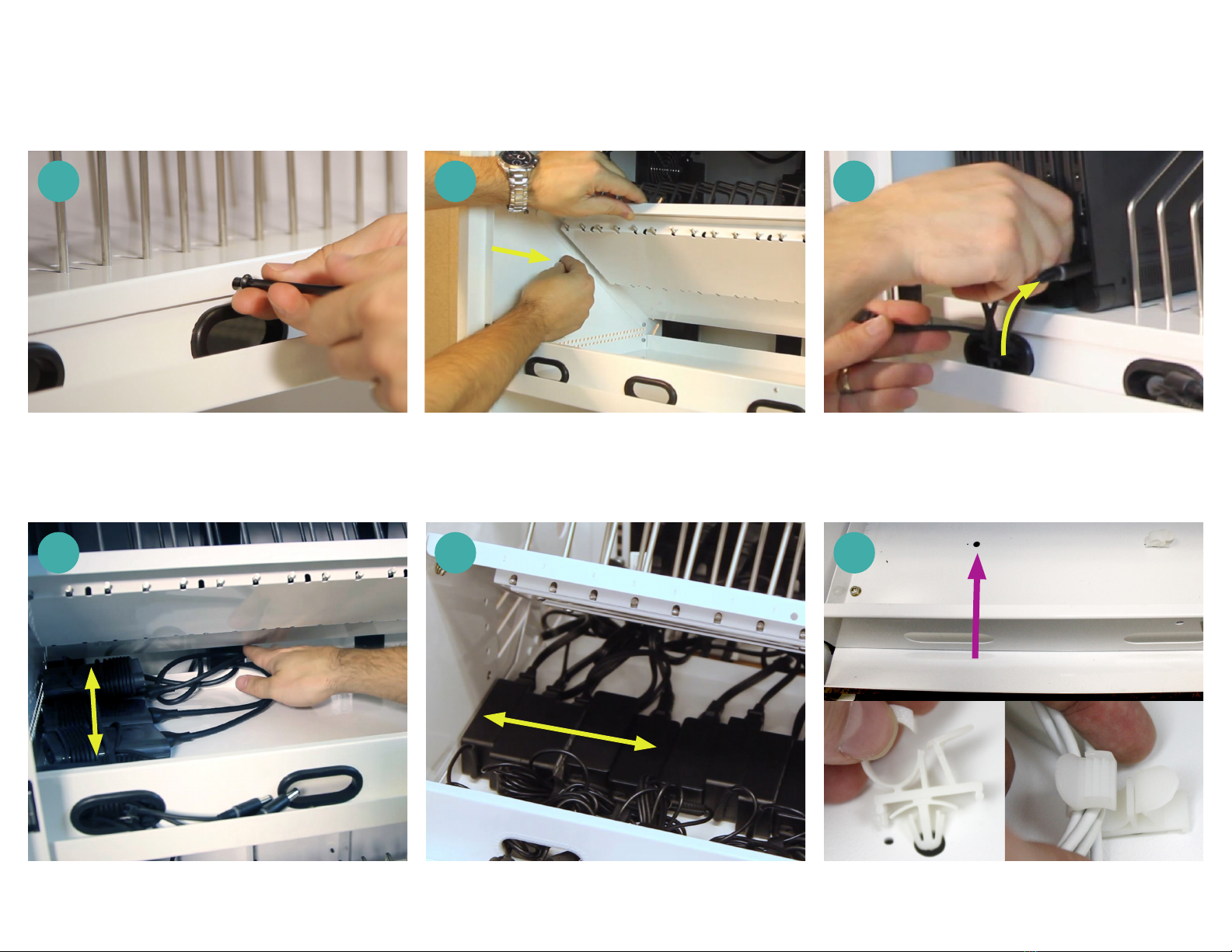
13: Find the plug end of the main power cable. Route
it down the opening in the top of the cart and out
of the opening on the left side of the cart. Plug the
socket end of the cable into the back of the Intelligent
Charging System. Pull any excess cable out of the cart
and wrap it around the brackets installed in step 9.
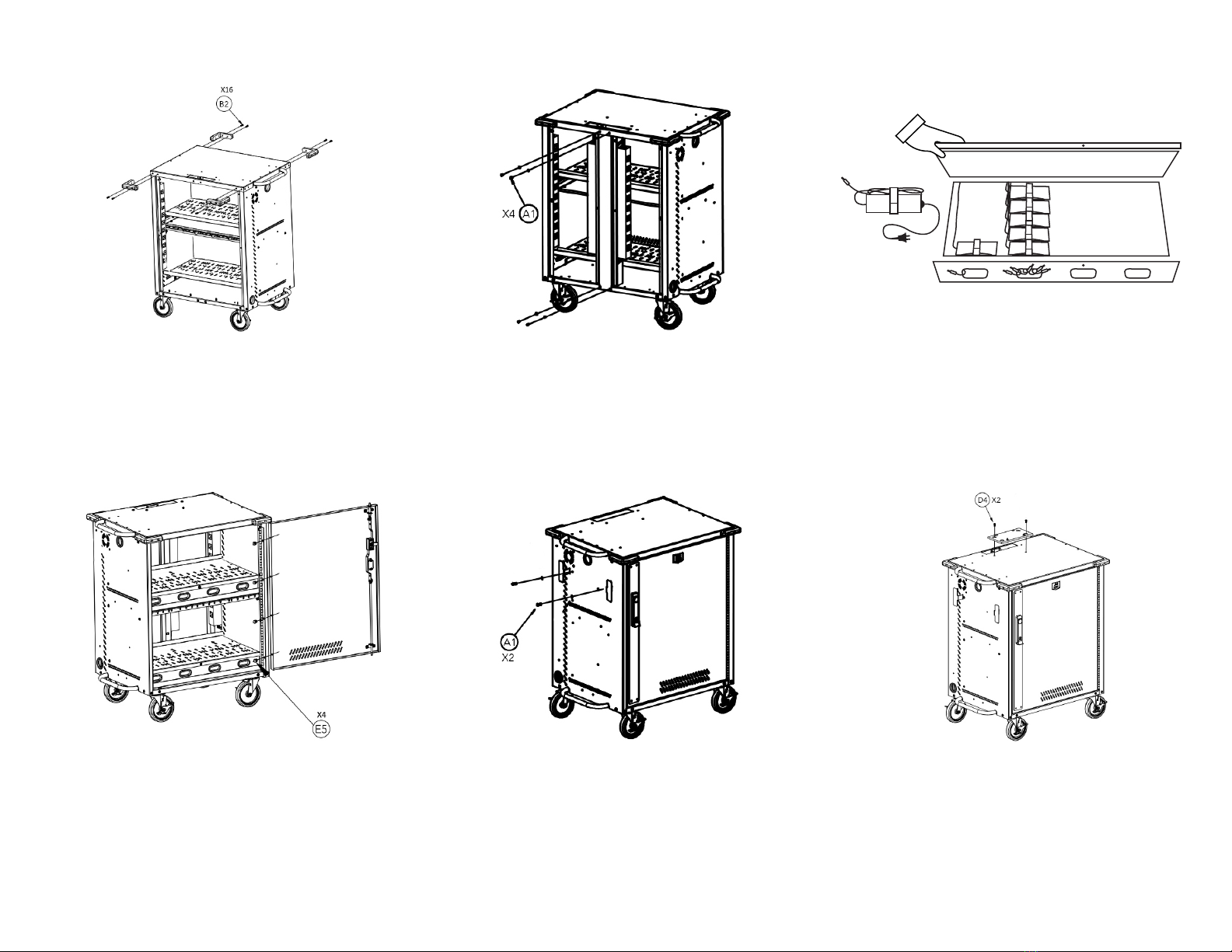
15: Install the cable cover over the back of the Intelligent
Charging System using 2 screws with washers (D4).
Use the Torx key (F6) to tighten the screws. Do not
use a power tool as it will leave scratches on the
cable cover.
16: Check the cart square by placing a rafter square in the
bottom corner of the door frame or use the door as
a guide. Check that the gap around the door edges
to make sure that it is even and the door has smooth
operation. Fully tighten screws on the left and right
sides of the cart.
17: Attach each of the rear access panels to the cart using
4 short screws with plastic washers (D4).To allow for
the cart to be squared in a later step, do not fully
tighten the screws during this step. Do not use a
power tool.
14: Route the 4 power strip cables through the hole in
the top of the cart. Looking at the cart from the back
side, plug the power strip that is farthest to the right
in the cart into the outlet in the back of the Intelligent
Charging System that is labeled “1” and repeat with
the following cables in order.
Cart Assembly Instructions

18: Check the cart square by placing a rafter square in the
bottom corner of the door frame or use the door as
a guide. Check that the gap around the door edges
to make sure that it is even and the door has smooth
operation. Fully tighten screws on the front and rear
sides of the cart.
19: Secure the top of the cart using 4 nuts (C3).
20: If the charging cables were not installed in step
8, install the cable management clips (G7, H8)
underneath each tray for later use. See page 6 for
further instructions on cable clips. Secure each tray
lid shut with one short screw with a silver washer (A1).
22: Insert the metal device dividers into the trays. See
page 8 for instructions on inserting the dividers.
21: MD-5150 Model Only- Locate the two screw holes
on the inside of the front door between the locking
hardware. With the swing handle in the open position,
align the hasp hardware with the two screw holes on
the front side of the handle. Insert the two included
screws from the inside of the door to secure. Padlocks
are not included.
23: To check that the charging system is properly
connected, plug the cart into a working outlet. The
Intelligent Charging System should make a brief
“beep” sound, the firmware version should display
in the LCD window, and a blue light will illuminate to
indicate the system is receiving power.

1: Remove the security screw using the provided Torx key (F6) from the center of the shelf (A) and temporarily
place it in the side of the cart (B) to hold the tray open during the wiring process.
3: Determine the best method of arranging the cables that come with your device (figures D, E, F below). Use of cable clips (G7, H8) is optional for any configuration.
2: Determine the length of cable that is needed to reach
from inside the tray to the devices (C).
Installing Charging Cables and Adapters
A B C
AC ADAPTERS FRONT TO BACK
Best for some wider adapters.
AC ADAPTERS LEFT TO RIGHT
Best for some narrower adapters.
D E
TABLET (NO AC ADAPTER)
Use provided clips beneath shelf to secure cables in groups of 5-6.
F

4: Arrange adapters in decided configuration, leaving
just enough cable length sticking out of the port to
plug in the devices.
TIPS:
Adapters can often be installed as they come bundled
in the box. For example, the adapter in figure (G)
comes with the cable wrapped around the adapter and
it works out nicely when installed in that condition. If
the cables are not bundled at all, twist ties or Velcro
ties may be helpful.
If the devices have particularly large AC adapters
(approximately 5” x 2” x 1.25”) the adapters will fit
more snugly in the tray. In this case it may be best to
arrange the majority of the adapters as far back in the
tray as possible from left to right, flipping about half
of them on their side. Please contact JAR Systems
for additional assistance.
5: Plug the charger into the power strip. For best results,
bundle any excess cable length if it is not already (H).
6: OPTIONAL- Replace the security screw in the center
of the shelf to prevent adapters from being removed
or tampered with (I).
EXAMPLE
H I
G

Installing Device Bays
40 DEVICE PATTERN
Best for devices up to 1” wide.
30 DEVICE PATTERN
Best for devices up to 1.25” wide.
28 DEVICE PATTERN
Best for devices up to 1.5” wide.
Service Plus carts feature adjustable device bays with multiple configuration options. This means that not every
slot in the tray will have a divider in it and there may be extra, unused dividers at the end of the assembly process
depending on which hole pattern is used. Use the guides below to determine which hole pattern to use.
To install the dividers, simply place the tall side of the divider into the rear slot first, then push in and down to get
the other side into the front slot.
30 DEVICE PATTERN
Best for devices up to 1” wide.
22 DEVICE PATTERN
Best for devices up to 1.25” wide.
20 DEVICE PATTERN
Best for devices up to 1.5” wide.
MD-5150-SP CART
MD-5135-SP CART
This manual suits for next models
2
Other JAR Systems Outdoor Cart manuals