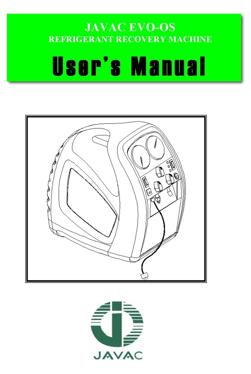
JAVAC XTR-ULTRA User manual

XTR-ULTRA
JAV-1063
XTR-ULTRA
REFRIGERANT RECOVERY
Safety Instructions & Operation Manual
Instructions de sécurité et notice d’utilisation
Sicherheitsanweisungen und Bedienungsanleitung
Instrucciones de seguridad y manual de funcionamiento
Istruzioni di sicurezza e manuale d’uso
EN
FE
DE
ES
IT
XTRULTRA-2 A5 safety-operation-manual.indd 1 01/02/2018 15:42

3
2
Thank you for purchasing a JAVAC Refrigerant Recovery Machine.
The device combines an innovative refrigerant gas compression system with a rugged, moulded case
that is designed to oer maximum protection from damage during tran-sit and normal handling. With
normal use and with care as prescribed in this manual, your machine will give you years of trouble-
free operation.
SAFETY FIRST
This international symbol is intended to alert the user to the presence of important operating, safety
and maintenance (servicing) instructions in this manual. As used in the manual, it is intended to draw
your attention to critical items.
IT IS IMPORTANT TO READ THIS ENTIRE MANUAL AND BE FAMILIAR WITH ITS CONTENTS
BEFORE USING THE MACHINE.
The XTR-ULTRA recovery machine is suited for a broad range of refrigerants. Recovering refrigerants
into a separate storage cylinder involves a process of gas compression, resulting in high pressures
within the machine, the connecting hoses and the storage cylinder. High-pressure systems must
always be treated with care and respect to prevent careless accidents.
PRODUCT SAFETY:
These units have been designed to meet the requirements of the Standard for Refrigerant Recovery
Machines, UL1963 and AS4211.3 - 1996. In order to fully meet safety requirements, the recovery
operation must always be performed using an approved storage cylinder. Additionally, approved
refrigerant hoses must be used which have shut-o devices within 12 inches (305mm) of the ends to
reduce the likelihood of refrigerant leakage to the atmosphere when changing cylinders or setups.
RESPONSIBILITY:
Only a qualied technician who has been properly trained in the care and use of such equipment
and in the recovery process itself must operate the JAVAC refrigerant recovery devices. Use of this
equipment by unqualied personnel is potentially dangerous and should not be attempted.
EN
XTR-ULTRA
REFRIGERANT RECOVERY MACHINE
XTRULTRA-2 A5 safety-operation-manual.indd 2 01/02/2018 15:42

3
CONTENTS
1.0 SAFETY PRECAUTIONS
2.0 SPECIFICATIONS
3.0 FEATURES
4.0 SET UP AND OPERATION
4.1 Getting Started
4.2 Normal Recovery Operation
4.3 Purging The Recovery Machine
4.4 Push Pull Operation
4.5 Special Operating Notes
4.6 Storage
5.0 APPROVED ACCESSORIES
6.0 MAINTENANCE
7.0 TROUBLE SHOOTING
8.0 SERVICE - CONSTRUCTION
9.0 WARRANTY
10.0 TRADE-IN AND SALES
11.0 HELP AND SUPPORT
XTRULTRA-2 A5 safety-operation-manual.indd 3 01/02/2018 15:42

5
4
EN
1.0 SAFETY PRECAUTIONS
1.1 THIS EQUIPMENT MUST ALWAYS BE OPERATED BY A QUALIFIED TECHNICIAN WHO
IS FAMILIAR WITH REFRIGERANT SYSTEMS, REFRIGERANTS, REFRIGERANT SAFETY AND
LOCAL REQUIREMENTS.
1.2 READ THIS MANUAL and become familiar with the specications and operation of this machine
prior to use.
1.3 WEAR APPROPRIATE SAFETY PROTECTION APPAREL such as gloves, eye protection and
foot protection when working on refrigeration systems.
1.4 REFRIGERANT VAPOUR CAN BE HAZARDOUS AND ITS BYPRODUCTS CAN BE LETHAL
- work only in well ventilated areas. When working indoors, ensure there is adequate airow in the
workspace and install a separate circulation fan if necessary. DO NOT WORK IN AN ENCLOSED
AREA without special safety equipment as appropriate for the conditions.
1.5 KNOW THE PROPER SAFETY AND HANDLING REQUIREMENTS for the refrigerant being
recovered by reviewing the Material Safety Data Sheets (MSDS) and the temperature - vapour
pressure information.
1.6 PERFORM LEAK DETECTION in accordance with recommended practice only. For best results
use only a refrigerant detector such as the JAVAC D-TEK or TEK- Mate. NEVER USE OXYGEN for
this process as it can become an explosive mixture in the presence of oil and pressure.
1.7 NEVER OVERFILL A STORAGE CONTAINER. The use of a refrigerant scale, such as the
JAVAC Pro-Charge, is required to prevent overll. OVERFILLED CYLINDERS CAN RUPTURE
EXPLOSIVELY!
1.8 STORE REFRIGERANTS in a cool, dry place.
1.9 SEPARATE DIFFERENT REFRIGERANTS. Avoid mixing refrigerants by using sepa-rate storage
cylinders and lters for each type recovered.
1.10 OPEN SERVICE OR CYLINDER VALVES SLOWLY to ensure that all connections are tight and
there is no danger.
1.11 DISCONNECT POWER before moving or servicing the recovery unit. CAUTION - these units
should be opened only by a technically qualied person who has been trained in basic electronics
and refrigeration. The risk of ELECTRIC SHOCK and exposure to HOT compressor parts is possible
if the unit is opened.
1.12 WARNING - TO REDUCE THE RISK OF FIRE, EXTENSION CORDS SHOULD NOT BE USED
with this equipment as the wiring can overheat under conditions of high current draw. If an extension
cord is absolutely necessary, its length should be as short as possible and it should contain size 16
AWG (1.291 mm) or larger wiring.
XTRULTRA-2 A5 safety-operation-manual.indd 4 01/02/2018 15:42

5
1.13 FLAMMABLE ENVIRONMENTS ARE DANGEROUS when any machine is used because
motors and switches can generate sparks. This equipment should be used in locations with
mechanical ventilation providing at least four air changes per hour, or the equipment should be
located at least 18” above the oor. DO NOT USE THIS EQUIPMENT IN THE VICINITY OF
SPILLED OR OPEN CONTAINERS OF GASOLINE OR ANY OTHER FLAMMABLE LIQUID.
1.14 MOISTURE can cause severe damage when introduced to the internal parts of a refrigeration
system. Ensure that care is exercised in the leak detection, recovery, repair and relling of a system
to prevent moisture from entering. Always use a quality high vacuum pump such as a Javac Vector
to ensure the system is totally dehydrated. An electronic total pressure gauge such as the JAVAC
Acravac should also be used to monitor the pressure.
1.15 WARNING. DO NOT USE THIS MACHINE WITH FLAMMABLE REFRIGERANTS.
1.16 USE CAUTION WHEN OPERATING OUTDOORS. Be certain that the power cord, the cylinder
safety cord and the unit itself are not placed in water or other potentially dangerous locations. While
these recovery machines are very safe to operate, using in environments such as hard rain or sand
and dust storms should be avoided.
1.17 CAUTION - EXERCISE CARE WHEN MOVING the equipment to prevent the risk of injury.
XTRULTRA-2 A5 safety-operation-manual.indd 5 01/02/2018 15:42

7
6
2.0 SPECIFICATIONS
EN
REF FEATURES TECHNICAL SPECIFICATIONS
2.1 Refrigerants EPA Certied to ARI 740-98 for refrigerants, HFC,HCFC and CFC
2.2 Safety Designed to meet UL1963, AS standards & EU equivalents
2.3 Power 220/240 VAC/50Hz, 110-115 VAC/50Hz
2.4 Compressor 3/4 HP oil less, BLDC motor drive
2.5 Cooling Fan direct
2.6 Protection High pressure switch cuto at 3850 Kpa
Compressor protected by brushless DC drive circuit
2.7 Pressure Max low side design pressure 2600Kpa
Max high side design pressure 3800Kpa
2.8 Temperature Operating range 10°C to 40°C
2.9 Case Injection moulded glass reinforced high impact
2.10 Size L 320mm X W 220mm X H 260mm
2.11 Weight 8.5 Kg
REFRIGERANT
LIQUID RATE
(Kg/Min) (Kg/Hr)
VAPOUR RATE
(Kg/Min) (Kg/Hr)
PUSH/PULL
RATE
(Kg/Min) (Kg/Hr)
RESIDUAL
TRAPPED
REFRIGERANT
(Kg)
R22 2.30/138 0.31/18.6 7.10/426 <0.1
R134-a 2.00/120 0.25/15 5.80/348 <0.1
R410A 1.65/99 0.30/18 7.00/420 <0.1
XTRULTRA-2 A5 safety-operation-manual.indd 6 01/02/2018 15:42

7
3.0 FEATURES
3.1 Designed with the highest quality components and manufactured in a quality controlled factory.
3.2 The JAVAC XTR-ULTRA utilizes new brushless DC, oil less compressor technology that is both
light weight and durable.
3.3 Factory tted with an inlet particle lter which traps contaminants. This lter is easy to remove,
clean or replace in the event of restricted ow.
3.4 Inlet (Suction) and discharge pressure gauges allow the process to be monitored from start to
nish.
3.5 The unit’s lightweight and excellent balance makes it easy to transport to the job site and into
dicult locations. The handle is easy to grasp and the unit is exceptionally well balanced.
3.6 The PURGE operation can be accomplished without changing hoses.
3.7 The high impact moulded case resists damage and is designed for the rigors of tradesman use.
XTRULTRA-2 A5 safety-operation-manual.indd 7 01/02/2018 15:42

9
8
EN
4.0 SET UP AND OPERATION
4.1 GETTING STARTED
4.1.1 CAUTION: Only personnel who have been properly trained in the use and operation of
refrigeration systems, refrigerants and service equipment should operate this equipment. Failure to
follow proper safety precautions could result in personal injury or death.
4.1.2 CAUTION: Review the full contents of this manual before attempting to use the recovery
machine in actual service.
4.1.3 Identify the refrigerant to be recovered and prepare the recovery unit for use by installing an
approved lter, hoses and scale as per the diagram below. Refer to section 5.0 of this manual for
approved accessories.
4.1.4 Connect the AC power cord to a circuit that is protected by a circuit breaker. Use an extension
cord only when absolutely necessary to perform the service; be sure it is the minimum length
required, that it contains a safety ground wire and that it contains wires sized 16 AWG (1.291 mm) or
larger.
4.1.5 Make sure the recovery unit is set in a stable position and that it is reasonably level; observe all
safety precautions previously noted. Ensure that the fan inlet and discharge areas on both sides of
the machine are clear from obstructions.
4.1.6 Check all connections to ensure they are tight before starting the recovery operation.
4.1.7 The XTR-ULTRA is a liquid tolerant recovery machine. It is important to remember to START the
machine before opening the INLET valve. Should the compressor start to ‘Knock’, close the INLET
valve immediately and while it is still running, slowly open the valve again.
4.1.8 Use a refrigerant scale to ensure that the cylinder is not lled to more than 80% of its capacity
by weight. When operating in the NORMAL RECOVERY or PUSH-PULL mode without the cylinder
shuto it is possible to overll the cylinder. If you are not sure, check the cylinder weight before
transporting. Refer to section 10.0 of this manual. OVERFILLED CYLINDERS CAN RUPTURE
EXPLOSIVELY!
XTRULTRA-2 A5 safety-operation-manual.indd 8 01/02/2018 15:42

9
4.2 NORMAL RECOVERY OPERATION
4.2.1 Connect all cables and hoses as described in Section 4.1 above and as shown in the diagram
below. Ensure that they are tight and routed in such a way that they will not interfere with the
operation.
SET-UP PROCEDURE FOR NORMAL REFRIGERANT RECOVERY
4.2.2 Switch o the power to the unit being serviced. If the power switch is in a remote location,
LOCK it out so that no one will accidentally turn it back on.
4.2.3 Purge hoses and machine as necessary. Do not use pure liquid refrigerant for this purpose as a
hydraulic lock and damage may occur upon start.
4.2.4 Set PURGE /RECOVERY valve (B) unit for RECOVERY.
4.2.4.1 OPEN DISCHARGE valve (C) to its fully open position.
4.2.4.2 Open tank valve.
4.2.4.3 Switch ON the recovery unit and verify that the compressor is operating.
4.2.5 Open the INLET valve (A) slowly and verify that no leaks are present. Open inlet valve fully for
vapour recovery or place it on the liquid setting for liquid recovery. If the compressor ‘knocks’ shut
the inlet valve (A) immediately. Reopen slowly ensuring the valve is throttling enough liquid refrigerant
to impede hydraulic lock and damage.
4.2.6 Monitor operation.
4.2.7 Continue to operate until the required VACUUM has been pulled on the system (refer to section
8.0 of this manual), as indicated by the LP gauge. Switch OFF the re-covery unit, CLOSE the INLET
(A), and wait for 5 minutes. If the pressure in the system, as indicated on the manifold gauge, rises
above 0 Kpa, refrigerant is still present. If so, RESTART recovery machine, reopen the INLET (A)
and run until the required VACUUM is reached again. Repeat this process until all the refrigerant is
removed resulting in a nal reading of 0 Kpa or less.
CYLINDER
SCALE
VAPOUR
FILTER
LIQUID
SYSTEM
LIQUID
XTRULTRA-2 A5 safety-operation-manual.indd 9 01/02/2018 15:42

11
10
EN
4.0 SET UP AND OPERATION continued
4.3 PURGING THE RECOVERY UNIT
4.3.1 While the recovery machine is running, rotate INLET Valve (A) to CLOSE position.
4.3.2 Rotate PURGE/RECOVERY valve (B) to PURGE position. Leave DISCHARGE (V3) open.
4.3.3 Slowly rotate Inlet valve (A) to PURGE position.
4.3.4 Observe LP gauge and continue to run the unit until a VACUUM is achieved. Switch POWER
OFF and CLOSE the recovery cylinder valve. Return INLET valve (A) to CLOSE position and close the
discharge valve (C).
4.3.5 IMPORTANT - Return Valve (B) to RECOVERY Position.
4.3.6 CAUTION - THE DISCHARGE PORT AND HOSE WILL CONTAIN A SMALL AMOUNT OF
REFRIGERANT UNDER PRESSURE. EXERCISE CARE WHEN REMOVING THIS HOSE AND
OPENING THE DISCHARGE VALVE (C).
4.4 PUSH/PULL OPERATION
SET-UP PROCEDURE FOR PUSH/PULL METHOD
LIQUID
CYLINDER
SCALE
VAPOUR
FILTER
LIQUID
SYSTEM
XTRULTRA-2 A5 safety-operation-manual.indd 10 01/02/2018 15:42

11
4.4.1 The PUSH PULL method is used to move a large amount of liquid refrigerant from the system
being serviced to the recovery cylinder without passing it through the compressor. This method is
only useful when more than 7 Kg of liquid is known to be in the system and it can be easily isolated.
DO NOT ATTEMPT the PUSH PULL process unless you are sure of the situation.
4.4.2 Connect the refrigerant hoses as shown below. Addition of a SIGHT GLASS in line between the
system being serviced and the recovery cylinder can be an important aid to determine when all the
liquid has been transferred and only vapour remains.
4.4.3 This process uses the PULL from the exhausted recovery cylinder and the Discharge PUSH
from the recovery unit to move the liquid refrigerant. Rates in excess of 5 Kg per minute can be
achieved by this procedure.
4.4.4 The SCALE is required in this process to ensure that the cylinder is not over-lled.
4.5 SPECIAL OPERATING NOTES
4.5.1 If during operation the high discharge pressure switch trips, take appropriate action to reduce
the discharge pressure before resetting the switch.
4.6 STORAGE
4.6.1 When the recovery process has been completed, carefully coil the power cord, the refrigerant
hoses and ensuring that no dirt or foreign material is left in the ends or on the connectors.
4.6.2 Place the recovery unit in the service vehicle in its upright position and store the hoses and
cords nearby. Provide reasonable care to place the unit where it will not be subjected to accidental
damage due to shifting items during transit or to heavier objects being placed on its top.
4.6.3 The unit can be stored safely in temperatures of 0°C-50°C and humidity levels up to
95% RH. When stored in conditions that are severe, the unit may need to stabilize in the range
10°C-40°C before it will oer optimum operating performance. For best results, store the unit in an
environmentally controlled area when not in use.
4.6.4 Always purge and vent the machine prior to storage, close valve A & C and leave C in the
Recover Position.
XTRULTRA-2 A5 safety-operation-manual.indd 11 01/02/2018 15:42

13
12
5.0 APPROVED ACCESSORY ITEMS
The XTR-ULTRA Refrigerant Recovery Machine requires the proper accessory items to ensure the
best performance. The following items are specically identied to ensure safety and operational
requirements are met. Check with your wholesaler to ensure that the proper selections have been
made.
5.1 REFRIGERANT HOSES should be made with approved materials, should be as short as
possible to perform the required operations and should have shut-o devices within 300mm of the
ends.
Approved hoses are: Refrigerant hoses with UL recognition and 27580 Kpa (275 bar/4000 PSI)
burst strength.
5.2 RECOVERY CYLINDERS should be approved and have an appropriate pressure rating for the
refrigerant being recovered. Choose the size that is right for the job.
5.3 FILTERS should be selected to protect the Inlet of the recovery machine from particles of
dust, metal and other foreign materials that may be present in the refrigeration system. If servicing
a system with a burned out compressor, 2 or more FILTERS in series may be necessary, and they
should be discarded immediately after use.
Approved lters are: Filters UL recognized/CSA listed for Refrigeration Service.
5.4 EXTENSION CORDS, when necessary, should be as short as possible and should contain size
16 AWG (1.291 mm) or larger conductors. This is necessary to avoid over-heating during periods of
high current draw and minimize the risk of re. The longer the extension cord required at the work
site, the larger the conductor size should be particularly for runs over 10m.
EN
XTRULTRA-2 A5 safety-operation-manual.indd 12 01/02/2018 15:42

13
6.0 MAINTENANCE
6.1 Your recovery machine will provide many seasons of reliable service if it is properly maintained.
The actual maintenance requirements are minimal but important.
6.2 Keep the unit clean by wiping it down with a damp cloth to remove dirt, oils, etc. Prior to storage
for the day. Standard household detergent or isopropyl alcohol may be used if the unit is particularly
dirty; in all cases, exercise care to prevent liquids from entering the unit. Gasoline and other solvents
are to be avoided as they can damage the plastic enclosure and are hazardous.
6.3 Clean inlet particle lter regularly. Discard internal lter screen if it is heavily contaminated and
replace with a new screen.
6.3.1 Using an inline lter drier is recommended for dirty systems or during refrigerant transfer.
6.4 Ensure that the inlet and discharge ports are protected and kept clean by replacing the plastic
caps after every use. For best results, keep a FILTER permanently con-nected to the INLET port and
change it regularly.
6.5 Change HOSES periodically as they develop leaks and a build-up of contaminants over time.
Change hoses at least once per season.
6.6 When storing the recovery machine for the season, or for long periods of time, PURGE the unit
with an inert gas such as nitrogen.
6.7 When performance falls o it is likely that the compressor seals require replacing. This is normal
with use and may occur after a year or two or more often, depending upon the conditions that are
prevalent during the recovery operations. Please contact your wholesaler for assistance in selecting
genuine spare parts.
XTRULTRA-2 A5 safety-operation-manual.indd 13 01/02/2018 15:42

15
14
7.0 TROUBLE-SHOOTING
EN
PROBLEM CAUSE ACTION
UNIT WILL NOT START
- COMPRESSOR DOES
NOT START; NO LIGHT IN
POWER SWITCH
• Power cord not attached
• No voltage at receptacle/
incorrect voltage
• Attach power cord
• Verify voltage at job site
COMPRESSOR WILL NOT
START
• Circuit breaker has opened
• Discharge pressure too high
• HP switch has opened
permanently
• Electrical overload on BLDC
controller
• Electronics failure in motor
circuit
• Thermal cut-out has
activated
• Identify cause of breaker
activation, rectify and reset
• Reduce pressure and rotate
C to purge and back to
recovery. Reset pressure
cut-out switch
• Factory service required
• Switch unit o for 10
seconds and restart
• Factory service required
• Allow motor to cool. If still
not working a factory service
is required
COMPRESSOR STARTS
BUT CUTS OUT WITHIN A
FEW MINUTES; PRESSURE
INDICATION ON HP GAUGE
IS HIGH
• B is in purge position and HP
switch activates
• C not open and HP switch
activates
• Recovery cylinder valve not
open
• Blocked discharge hose
• Air in system/cylinder
• Rotate B to recovery
• Rotate C to open position
• Open cylinder valve
• Check & clear blockage
• Bleed air from system/
cylinder
COMPRESSOR STOPS • Vapour pressure of
refrigerant in cylinder is close
to HP trip point
• Reduce cylinder temperature
XTRULTRA-2 A5 safety-operation-manual.indd 14 01/02/2018 15:42

15
PROBLEM CAUSE ACTION
UNIT OVERHEATS Excessive head pressure
due to:
• High ambient temperature
• Restricted discharge hose
• Air in recovery cylinder
• Fan not turning
• Reduce cylinder temperature
• Check & clear restriction
• Bleed air from cylinder
• Factory service required
RECOVERY PROCESS TOO
SLOW
• Head pressure too high
• System refrigerant iced up
• Compressor seals are worn
• Inlet lter blocked
• Reduce cylinder temperature
or change cylinders
• Heat up or wait
• Interrupt process to allow ice
to dissipate
• Factory service required
• Remove lter and clean/
replace cone screen
XTRULTRA-2 A5 safety-operation-manual.indd 15 01/02/2018 15:42

17
16
8.0 SERVICE - CONSTRUCTION AND SCHEMATIC
8.1 SERVICE
8.1.1 The XTR ULTRA uses only UL, CSA or TUV recognised electrical components or components
which have been specially designed for this application.
8.1.2 DO NOT CHANGE any of these components as the safety of the machine could be
compromised. All service work must be performed at a JAVAC approved facility in order to maintain
the safety rating and the Warranty, if applicable.
8.1.3 Technical assistance and service information can be obtained by calling the Organisation where
you purchased the recovery machine.
NOTE: Do not return a defective unit directly to the factory. Contact your wholesaler or the
factory for assistance.
8.1.4 Spare parts and accessories (see 8.3) for your XTR-ULTRA are available through the same
dealer from whom you purchased the unit.
8.1.5 Disassembly of the unit to rebuild the compressor or to provide other repair work should be
referred to an approved service centre.
8.2 CONSTRUCTION
8.2.1 The JAVAC recovery machines are constructed from the highest grade materials to exacting
standards. All assembly and testing is performed in an ISO 9001 registered facility.
8.2.2 This unit is manufactured with environmentally compatible components, which can be
substantially recycled at the end of the product’s useful life. Consult your local agencies for proper
recycling.
8.2.3 The JAVAC recovery machines contain no hazardous materials.
8.3 SPARE PARTS
JAVAC oer a complete range of product spares. Visit our website: javac.co.uk or contact your local
wholesaler for details.
EN
XTRULTRA-2 A5 safety-operation-manual.indd 16 01/02/2018 15:42

17
9.0 WARRANTY
9.1 JAVAC warrants your XTR-ULTRA refrigerant recovery machine to be free from defects of
materials or workmanship for one year from the date of purchase. JAVAC does not warrant any
machine that has been subjected to misuse, negligence, or accident, or has been repaired or altered
by anyone other than JAVAC. The XTR-ULTRA is designed and manufactured as a general recovery
machine for intermittent operation. For instance in commercial applications involving high duty
cycles or continuous running, the XTR-ULTRA is warranted for a period of 3 months from the date of
purchase.
9.2 The manufacturer warrants the compressor for a period of one year. To keep this WARRANTY in
force it is required that the standard lter and a lter drier be used on the inlet port or hose at all times
to prevent particulates from entering the com-pressor. Damage from excessive liquid ingress will void
the compressor warranty. FAILURE TO USE A FILTER WILL VOID THE COMPRESSOR WARRANTY.
9.3 JAVAC’s liability is limited to machines returned to JAVAC, return transporta-tion prepaid,
not later than thirty (30) days after the warranty period expires, and which JAVAC judges to have
malfunctioned because of defective materials or workmanship. JAVAC’s liability is limited to, at its
option, repairing or replacing the defective machine or part.
9.4 This WARRANTY is in lieu of all other warranties, expressed or implied, whether of
MERCHANTABILITY or of FITNESS FOR A PARTICULAR PURPOSE or otherwise. All such other
warranties are expressly disclaimed. JAVAC practices continuous product research and improvement.
We reserve the right to change specications and product design without notice. Such revisions
do not entitle the buyer to corresponding changes, improvements, additions or replacements for
previously purchased equipment.
9.5 JAVAC shall have no liability in excess of the price paid to JAVAC for the machine plus return
transportation charges prepaid. JAVAC shall have no liability for any incidental or consequential
damages. All such liabilities are EXCLUDED.
XTRULTRA-2 A5 safety-operation-manual.indd 17 01/02/2018 15:42

19
18
10.0 TRADE-INS & SALES
Please speak to our service team for XTR-ULTRA trade-ins and purchase of new recovery units. As
an existing JAVAC customer, we are committed to give ongoing support and after sales service.
CALL JAVAC +44 (0) 1642 232880
11.0 HELP & SUPPORT
Only JAVAC know how to service your vacuum and recovery equipment:
• SERVICE SUPPORT
• WARRANTY CLAIMS
• REPAIRS
• TECHNICAL ADVICE
• IMMEDIATE ATTENTION
For details on shipping direct to JAVAC.
Don’t trust “just any one” with your service tools.
You will receive fast, friendly service, but more importantly, speak to the people who designed and
manufactured your vacuum pump and who have the technical expertise to keep it in action!
FOR MORE INFORMATION ON PRODUCTS OR TECHNICAL ASSISTANCE VISIT OUR WEBSITE:
www.javac.co.uk
EN
XTRULTRA-2 A5 safety-operation-manual.indd 18 01/02/2018 15:42

19
Merci d’avoir acheté une station de récupération de uides frigorigènes
JAVAC.
Associant un système innovant de compression des gaz réfrigérants avec une coque moulée robuste,
ce dispositif ore une protection maximale contre les dommages pendant le transport et pendant la
manutention normale. Si vous respectez les consignes d’utilisation et d’entretien du présent manuel,
votre station fonctionnera sans problèmes pendant de nombreuses années.
LA SÉCURITÉ D’ABORD
Ce symbole international vise à alerter l’utilisateur de la présence d’importantes consignes
concernant l’utilisation, la sécurité et la maintenance (entretien) dans le présent manuel. Utilisé dans
le présent manuel, il a pour but d’attirer votre attention sur des points critiques.
IL EST IMPORTANT DE LIRE L’INTÉGRALITÉ DU PRÉSENT MANUEL ET DE VOUS
FAMILIARISER AVEC SON CONTENU AVANT D’UTILISER LA MACHINE.
La station de récupération XTR-ULTRA est destinée à un large éventail de uides frigorigènes. La
récupération des uides frigorigènes dans une bouteille de stockage séparée implique un processus
de compression des gaz qui produit de hautes pressions au sein de la station, des exibles de
raccordement et de la bouteille de stockage. Les systèmes haute pression doivent toujours être
manipulés avec soin et dans le respect des procédures an d’éviter tout accident.
SÉCURITÉ DES PRODUITS:
Ces stations ont été conçues conformément aux exigences de la directive sur les stations de
récupération des uides frigorigènes UL1963 et AS4211.3 - 1996. Pour satisfaire pleinement à
ces exigences de sécurité, l’opération de récupération doit toujours être eectuée en utilisant une
bouteille de stockage homologuée. En outre, il convient d’utiliser des exibles de uides frigorigènes
approuvés avec dispositifs d’arrêt installés à moins de 30,5 cm des extrémités, an de réduire
les risques de fuite de uides frigorigènes dans l’atmosphère au moment du remplacement des
bouteilles ou des congurations.
RESPONSABILITÉ :
Les dispositifs de récupération de uides frigorigènes JAVAC doivent être utilisés uniquement par un
technicien qualié, correctement formé à la manipulation et à l’utilisation de tels équipements. Nul
personnel non qualié ne doit tenter d’utiliser cet équipement, sous risque de s’exposer à un danger
potentiel.
FR
XTR-ULTRA
STATION DE RÉCUPÉRATION DE FLUIDE
FRIGORIGÈNE
XTRULTRA-2 A5 safety-operation-manual.indd 19 01/02/2018 15:42

21
20
TABLE DES MATIÈRES
1.0 PRÉCAUTIONS DE SÉCURITÉ
2.0 CARACTÉRISTIQUES
3.0 FONCTIONS
4.0 INSTALLATION ET UTILISATION
4.1 Démarrage
4.2 Opération de récupération normale
4.3 Purge de la station de récupération
4.4 Opération en surpression
4.5 Remarques spéciales concernant le fonctionnement
4.6 Stockage
5.0 ACCESSOIRES APPROUVÉS
6.0 MAINTENANCE
7.0 DÉPANNAGE
8.0 ENTRETIEN - CONSTRUCTION
9.0 GARANTIE
10.0 REPRISES ET VENTES
11.0 AIDE ET ASSISTANCE
FR
XTRULTRA-2 A5 safety-operation-manual.indd 20 01/02/2018 15:42
Table of contents
Languages:
Other JAVAC Test Equipment manuals
Popular Test Equipment manuals by other brands

ISA
ISA MC5 user guide

PCE Americas
PCE Americas PCE-HFX 100 user manual

Envitec
Envitec AlcoQuant 6020 operating instructions

VOLTCRAFT
VOLTCRAFT VC36 operating instructions

Keysight Technologies
Keysight Technologies N7015A Quick Start and Accessories Guide

Applent Instruments
Applent Instruments AT851 user guide